steering FIAT FREEMONT 2013 Owner handbook (in English)
[x] Cancel search | Manufacturer: FIAT, Model Year: 2013, Model line: FREEMONT, Model: FIAT FREEMONT 2013Pages: 352, PDF Size: 5.22 MB
Page 199 of 352
The side air bags will not deploy in all side collisions.
Side air bag deployment will depend on the severity and
type of collision.
Because air bag sensors measure vehicle deceleration
over time, vehicle speed and damage by themselves are
not good indicators of whether or not an air bag should
have deployed.
Seat belts are necessary for your protection in all
collisions, and also are needed to help keep you in
position, away from an inflating air bag.
The ORC monitors the readiness of the electronic
parts of the air bag system whenever the ignition is in
the ON/RUN position. If the ignition is in the OFF
position, or in the ACC position, the air bag system is
not on and the air bags will not inflate.
The ORC contains a backup power supply system that
may deploy the air bags even if the battery loses power
or it becomes disconnected prior to deployment.Also, the ORC turns on the Air Bag Warning
Light in the instrument panel for approxi-
mately four to eight seconds for a self-check
when the ignition is first turned on. After the self-
check, the Air Bag Warning Light will turn off. If the
ORC detects a malfunction in any part of the system, it
turns on the Air Bag Warning Light, either momentarily or continuously. A single chime will sound if the light
comes on again after initial startup.
It also includes diagnostics that will illuminate the
instrument cluster Air Bag Warning Light if a malfunc-
tion is noted that could affect the air bag system. The
diagnostics also record the nature of the malfunction.
WARNING!
Ignoring the Air Bag Warning Light in
y
our instrument panel could mean you
won't have the air bags to protect you in a
collision. If the light does not come on as a bulb
check when the ignition is first turned on, stays
on after you start the vehicle, or if it comes on as
you drive, have an authorized dealer service the
air bag system immediately.
Driver And Passenger Advanced Front Air Bag
Inflator Units
The Driver and Passenger Advanced Front Air Bag
Inflator Units are located in the center of the steering
wheel and on the right side of the instrument panel.
When the ORC detects a collision requiring the Ad-
vanced Front Air Bags, it signals the inflator units. A
large quantity of non-toxic gas is generated to inflate
the Advanced Front Air Bags. Different air bag inflation
rates are possible, based on several factors, including
the collision type and severity. The steering wheel hub
193KNOWING
YOUR
VEHICLE
SAFETY
STARTING
AND
DRIVING
W
ARNING
LIGHTS
AND
MESSAGES
IN AN
EMERGENCY
SERVICING
AND
CARETECHNICAL
SPECIFICATIONSCONTENTS
Page 207 of 352
PERIODIC SAFETY CHECKS YOU SHOULD
MAKE OUTSIDE THE VEHICLE
Tires
Examine tires for excessive tread wear and uneven
wear patterns. Check for stones, nails, glass, or other
objects lodged in the tread or sidewall. Inspect the
tread for cuts and cracks. Inspect sidewalls for cuts,
cracks and bulges. Check the wheel nuts for tightness.
Check the tires (including spare) for proper cold infla-
tion pressure.
Lights
Have someone observe the operation of brake lights
and exterior lights while you work the controls. Check
turn signal and high beam indicator lights on the instru-
ment panel.Door Latches
Check for positive closing, latching, and locking.
Fluid Leaks
Check area under vehicle after overnight parking for
fuel, engine coolant, oil, or other fluid leaks. Also, if
gasoline fumes are detected or if fuel, power steering
fluid, or brake fluid leaks are suspected, the cause
should be located and corrected immediately.
201
KNOWING
YOUR
VEHICLE
SAFETY
STARTING
AND
DRIVING
WARNING
LIGHTS
AND
MESSAGES
IN AN
EMERGENCY
SERVICING
AND
CARETECHNICAL
SPECIFICATIONSCONTENTS
Page 236 of 352
WARNING!
Improper towing can lead to an injury
ac
cident . Follow these guidelines to
make your trailer towing as safe as possible:
Make certain that the load is secured in the trailer
and that it will not shift during travel.When trailering
cargo that is not fully secured, dynamic load shifts can
occur that may be difficult for the driver to control.
You could lose control of your vehicle and have an
accident .
All trailer hitches should be professionally
installed on your vehicle.
When hauling cargo or towing a trailer, do not
overload your vehicle or trailer. Overloading can
cause a loss of control, poor performance, or
damage to brakes, axle, engine, transmission,
steering, suspension, chassis structure, or tires.
Safety chains must always be used between
your vehicle and trailer. Always connect the
chains to the frame or hook retainers of the
vehicle hitch. Cross the chains under the trailer
tongue and allow enough slack for turning cor-
ners.
(Continued)(Continued)
Vehicles with trailers should not be parked on
a grade. When parking, apply the parking brake
on the tow vehicle. Always, block or "chock" the
trailer wheels.
GCWR must not be exceeded.
Total weight must be distributed between the
tow vehicle and the trailer such that the following
four ratings are not exceeded:
1. GVWR
2. GTW
3. GAWR
4. Tongue weight rating for the trailer hitch uti- lized.
Towing Requirements – Tires
– Do not attempt to tow a trailer while using a compact spare tire.
– Proper tire inflation pressures are essential for the safe and satisfactory operation of your vehicle. Refer
to “Tires – General Information” in “Technical Speci-
fications” for proper tire inflation procedures.
– Check the trailer tires for proper tire inflation pres- sures before trailer usage.
230
KNOWING YOUR
VEHICLE
SAFETY
STARTING AND
DRIVING
WARNING LIGHTSAND
MESSA
GES
IN AN
EMERGENCY
SERVICING AND
CARETECHNICAL
SPECIFICATIONSCONTENTS
Page 246 of 352
cycles, and the vehicle has been driven several kilome-
ters at speeds greater than 48 km/h, see your autho-
rized dealer as soon as possible to have the problem
diagnosed and corrected.
NOTE:
The “ESC Off Indicator Light” and the “ESC
Activation/Malfunction Indicator Light” come on mo-
mentarily each time the ignition switch is turned to
ON/RUN.
Each time the ignition is turned to ON/RUN, the ESC
system will be ON, even if it was turned off previously.
The ESC system will make buzzing or clicking sounds
when it is active. This is normal; the sounds will stop
when ESC becomes inactive following the maneuver
that caused the ESC activation.
4. Turn Signal Indicator LightThe left or right arrow will flash in unison
with the corresponding front and rear turn
signal lights when the turn signal switch is
operated. (Refer to “Lights” in “Knowing
Your Vehicle” for further information).
NOTE:
A chime will sound if the vehicle is driven more than
1.6 km with either turn signal on. Check for an inoperative outside light bulb if either
indicator flashes at a rapid rate.
5. High Beam Indicator
This light shows that the high beam headlights
are on. Pull the multifunction lever on the left
side of the steering column toward you to switch to
low beam. (Refer to “Lights” in “Knowing Your Vehicle”
for further information).
6. Front Fog Light Indicator (for versions/markets,
where provided) This indicator will illuminate when the front fog
lights are on. (Refer to “Lights” in “Knowing
Your Vehicle” for further information).
7. Odometer Display / Electronic Vehicle Informa-
tion Center (EVIC) Display
Odometer
The odometer display shows the total distance the
vehicle has been driven.
Electronic Vehicle Information Center (EVIC) Dis-
play
The Electronic Vehicle Information Center (EVIC) fea-
tures a driver-interactive display that is located in the
instrument cluster. For further information, refer to
“Electronic Vehicle Information Center (EVIC)” in
“Knowing Your Vehicle”.
240
KNOWING YOUR
VEHICLE
SAFETY
STARTING AND
DRIVING
WARNING LIGHTSAND
MESSA
GES
IN AN
EMERGENC
Y
SERVICING AND
CARETECHNICAL
SPECIFICATIONSCONTENTS
Page 272 of 352

4. Install the bulb and connector assembly into theheadlamp housing and rotate it ¼ turn clockwise to
lock it in place.
FRONT FOG LAMP
NOTE: Turn the steering wheel to the right if replac-
ing the left front fog lamp or to the left if replacing the
right front fog lamp to allow for easier access to the
front of the wheel well.
1. Remove the fasteners retaining the front lower wheel well access panel and remove the access
panel.
2. Remove the electrical connector from the fog lamp housing. (fig. 162)
3. Firmly grasp the bulb by the two side latches and squeeze them together to unlock the bulb from the
back of the front fog lamp housing.
4. Pull the bulb straight out from the keyed opening in the housing.
5. Align the index tabs of the replacement front fog lamp bulb with the slots in the collar of the bulb
opening on the back of the front fog lamp housing.(fig. 161)1 — Front Turn Signal Lamp Bulb
2 — Low Beam Headlamp Bulb
3 — Front Position Bulb
4 — High Beam Headlamp Bulb
(fig. 162)
266
KNOWING YOUR
VEHICLE
SAFETY
STARTING AND
DRIVING
WARNING LIGHTSAND
MESSAGES
IN AN
EMERGENC
Y
SERVICING AND
C
ARETECHNICAL
SPECIFICATIONSCONTENTS
Page 277 of 352
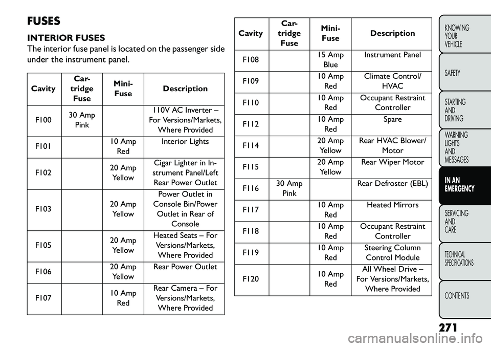
FUSES
INTERIOR FUSES
The interior fuse panel is located on the passenger side
under the instrument panel.CavityCar-
tridge Fuse Mini-
Fuse Description
F100 30 Amp
Pink 110V AC Inverter –
For Versions/Markets, Where Provided
F101 10 Amp
Red Interior Lights
F102 20 Amp
Yellow Cigar Lighter in In-
strument Panel/Left Rear Power Outlet
F103 20 Amp
Yellow Power Outlet in
Console Bin/Power
Outlet in Rear of Console
F105 20 Amp
Yellow Heated Seats – For
Versions/Markets,Where Provided
F106 20 Amp
Yellow Rear Power Outlet
F107 10 Amp
Red Rear Camera – For
Versions/Markets,Where Provided
Cavity Car-
tridge Fuse Mini-
Fuse Description
F108 15 Amp
Blue Instrument Panel
F109 10 Amp
Red Climate Control/
HVAC
F110 10 Amp
Red Occupant Restraint
Controller
F112 10 Amp
Red Spare
F114 20 Amp
Yellow Rear HVAC Blower/
Motor
F115 20 Amp
Yellow Rear Wiper Motor
F116 30 Amp
Pink Rear Defroster (EBL)
F117 10 Amp
Red Heated Mirrors
F118 10 Amp
Red Occupant Restraint
Controller
F119 10 Amp
Red Steering Column
Control Module
F120 10 Amp
Red All Wheel Drive –
For Versions/Markets, Where Provided
271
KNOWING
YOUR
VEHICLE
SAFETY
STARTING
AND
DRIVING
WARNING
LIGHTS
AND
MESSAGES
IN AN
EMERGENCY
SERVICING
AND
C ARETECHNICAL
SPECIFICATIONSCONTENTS
Page 278 of 352
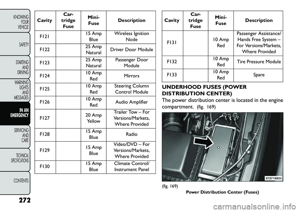
CavityCar-
tridge Fuse Mini-
Fuse Description
F121 15 Amp
Blue Wireless Ignition
Node
F122 25 Amp
Natural Driver Door Module
F123 25 Amp
Natural Passenger Door
Module
F124 10 Amp
Red Mirrors
F125 10 Amp
Red Steering Column
Control Module
F126 10 Amp
Red Audio Amplifier
F127 20 Amp
Yellow Trailer Tow – For
Versions/Markets, Where Provided
F128 15 Amp
Blue Radio
F129 15 Amp
Blue Video/DVD – For
Versions/Markets, Where Provided
F130 15 Amp
Blue Climate Control/
Instrument Panel
Cavity Car-
tridge Fuse Mini-
Fuse Description
F131 10 Amp
Red Passenger Assistance/
Hands Free System –
For Versions/Markets, Where Provided
F132 10 Amp
Red Tire Pressure Module
F133 10 Amp
Red Spare
UNDERHOOD FUSES (POWER
DISTRIBUTION CENTER)
The power distribution center is located in the engine
compartment. (fig. 169)(fig. 169)
Power Distribution Center (Fuses)
272
KNOWING YOUR
VEHICLE
SAFETY
STARTING AND
DRIVING
WARNING LIGHTSAND
MESSAGES
IN AN
EMERGENC
Y
SERVICING AND
C
ARETECHNICAL
SPECIFICATIONSCONTENTS
Page 281 of 352
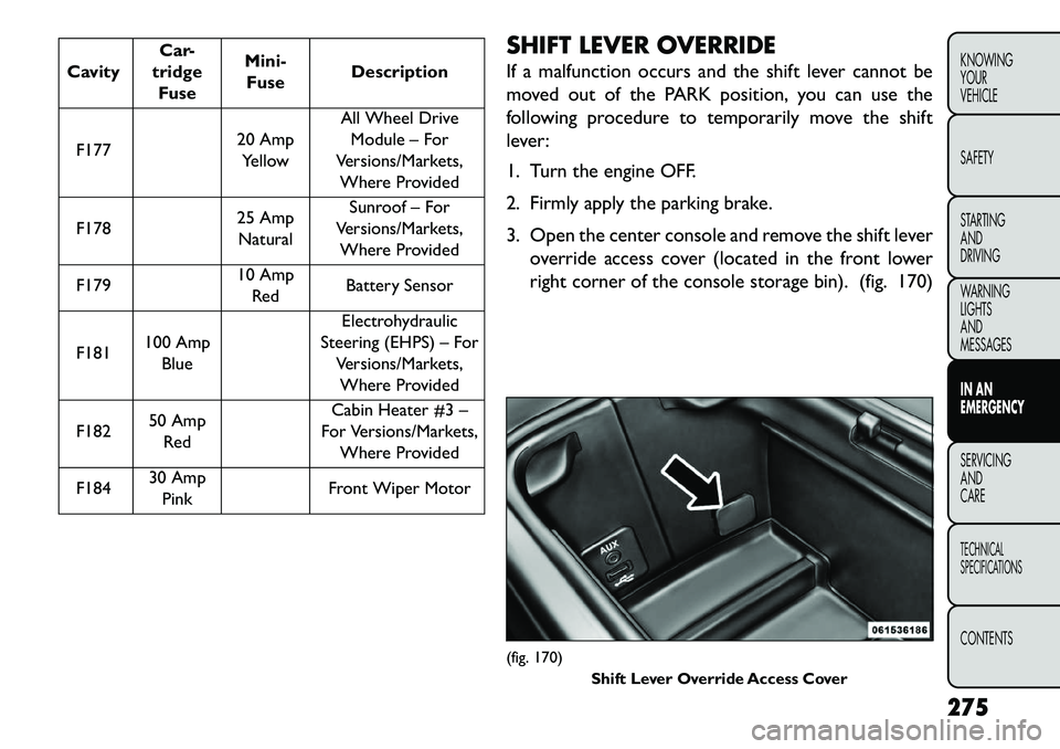
CavityCar-
tridge Fuse Mini-
Fuse Description
F177 20 Amp
Yellow All Wheel Drive
Module – For
Versions/Markets, Where Provided
F178 25 Amp
Natural Sunroof – For
Versions/Markets, Where Provided
F179 10 Amp
Red Battery Sensor
F181 100 Amp
Blue Electrohydraulic
Steering (EHPS) – For Versions/Markets,Where Provided
F182 50 Amp
Red Cabin Heater #3 –
For Versions/Markets, Where Provided
F184 30 Amp
Pink Front Wiper Motor SHIFT LEVER OVERRIDE
If a malfunction occurs and the shift lever cannot be
moved out of the PARK position, you can use the
following procedure to temporarily move the shift
lever:
1. Turn the engine OFF.
2. Firmly apply the parking brake.
3. Open the center console and remove the shift lever
override access cover (located in the front lower
right corner of the console storage bin). (fig. 170)
(fig. 170) Shift Lever Override Access Cover
275
KNOWING
YOUR
VEHICLE
SAFETY
STARTING
AND
DRIVING
WARNING
LIGHTS
AND
MESSAGES
IN AN
EMERGENCY
SERVICING
AND
C ARETECHNICAL
SPECIFICATIONSCONTENTS
Page 282 of 352
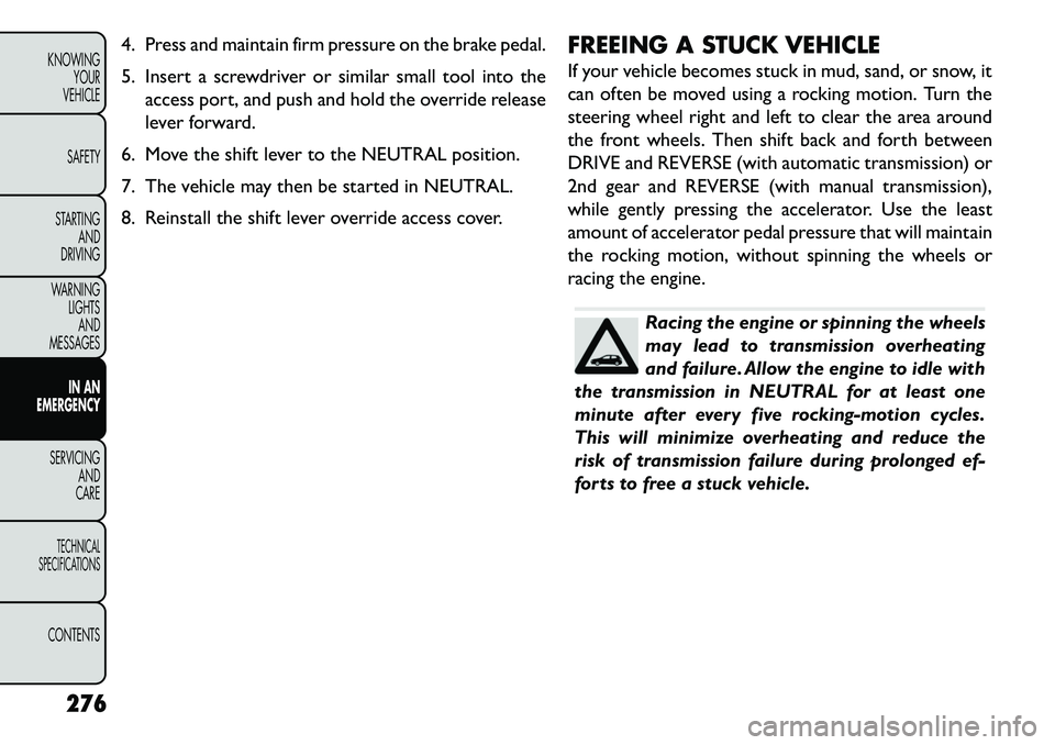
4. Press and maintain firm pressure on the brake pedal.
5. Insert a screwdriver or similar small tool into theaccess port, and push and hold the override release
lever forward.
6. Move the shift lever to the NEUTRAL position.
7. The vehicle may then be started in NEUTRAL.
8. Reinstall the shift lever override access cover. FREEING A STUCK VEHICLE
If your vehicle becomes stuck in mud, sand, or snow, it
can often be moved using a rocking motion. Turn the
steering wheel right and left to clear the area around
the front wheels. Then shift back and forth between
DRIVE and REVERSE (with automatic transmission) or
2nd gear and REVERSE (with manual transmission),
while gently pressing the accelerator. Use the least
amount of accelerator pedal pressure that will maintain
the rocking motion, without spinning the wheels or
racing the engine.
Racing the engine or spinning the wheels
may lead to transmission overheating
and failure. Allow the engine to idle with
the transmission in NEUTRAL for at least one
minute after every five rocking-motion cycles.
This will minimize overheating and reduce the
risk of transmission failure during prolonged ef-
forts to free a stuck vehicle.
276
KNOWING YOUR
VEHICLE
SAFETY
STARTING AND
DRIVING
WARNING LIGHTSAND
MESSAGES
IN AN
EMERGENC
Y
SERVICING AND
C
ARETECHNICAL
SPECIFICATIONSCONTENTS
Page 287 of 352
Do not use sling type equipment when
towing. Damage to the fascia will occur.
When securing the vehicle to a flatbed
truck, do not attach to front or rear suspension
components. Damage to your vehicle may result
from improper towing.
Do not push or tow this vehicle with another
vehicle as damage to the bumper fascia and trans-
mission may result .
If the vehicle being towed requires steering, the
ignition switch must be in the ON/RUN position,
not in the OFF or ACC position.
WITHOUT THE KEY FOB
Special care must be taken when the vehicle is towed
with the ignition in the OFF position. Flatbed towing is
the preferred towing method. However, if a flatbed
towing vehicle is not available, wheel lift towing equip-
ment may be used. Rear towing (with the front wheels
on the ground) is not allowed, as transmission damage
will occur. If rear towing is the only alternative, the
front wheels must be placed on a towing dolly. Proper
towing equipment is necessary to prevent damage to
the vehicle. All-Wheel Drive (AWD) Models
The manufacturer requires towing with all four wheels
OFF
the ground. Acceptable methods are to tow the
vehicle on a flatbed, or with one end of vehicle raised
and the opposite end on a towing dolly.
Failure to follow these towing methods
can cause severe damage to the trans-
mission and/or transfer case. Such dam-
age is not covered by the New Vehicle Limited
Warranty.
281
KNOWING
YOUR
VEHICLE
SAFETY
STARTING
AND
DRIVING
WARNING
LIGHTS
AND
MESSAGES
IN AN
EMERGENCY
SERVICING
AND
C ARETECHNICAL
SPECIFICATIONSCONTENTS