engine FIAT FREEMONT 2015 1.G Repair Manual
[x] Cancel search | Manufacturer: FIAT, Model Year: 2015, Model line: FREEMONT, Model: FIAT FREEMONT 2015 1.GPages: 412, PDF Size: 3.37 MB
Page 285 of 412
IN AN EMERGENCY
JUMP-STARTING
If your vehicle has a discharged battery it can be
jump-started using a set of jumper cables and a battery
in another vehicle or by using a portable battery
booster pack. Jump-starting can be dangerous if done
improperly so please follow the procedures in this
section carefully.
WARNING!
Do not attempt jump-starting if the bat-
tery is
frozen. It could rupture or explode
and cause personal injury.
Do not use a portable battery booster
pack or any other booster source with a
system voltage greater than 12 Volts or
damage to the battery, starter motor, alternator
or electrical system may occur.
NOTE: When using a portable battery booster pack
follow the manufacturer's operating instructions and
precautions. PREPARATIONS FOR JUMP-START
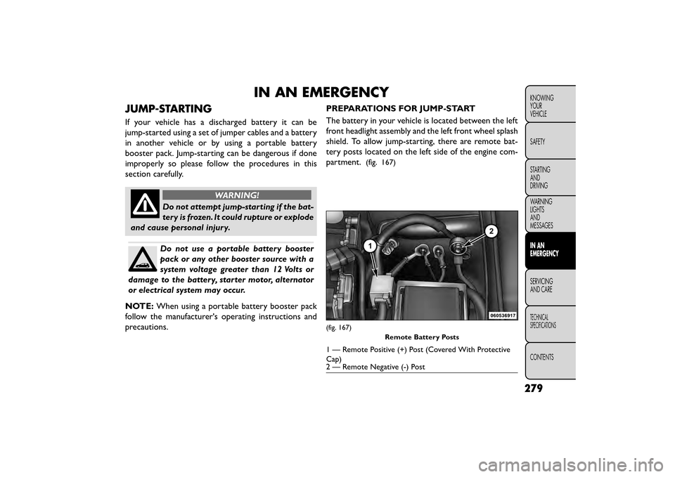
The battery in your vehicle is located between the left
front headlight assembly and the left front wheel splash
shield. To allow jump-starting, there are remote bat-
tery posts located on the left side of the engine com-
partment.
(fig. 167)
(fig. 167)
Remote Battery Posts
1 — Remote Positive (+) Post (Covered With Protective
Cap)
2 — Remote Negative (-) Post
279
KNOWING
YOUR
VEHICLE
SAFETY
STARTING
AND
DRIVING
WARNING
LIGHTS
AND
MESSAGES
IN AN
EMERGENCY
SERVICING
AND
CARE
TECHNICAL
SPECIFICATIONS
CONTENTS
Page 287 of 412
4. Connect the opposite end of the negative(-)
jumper cable to the remote negative (-)post of the
vehicle with the discharged battery.
WARNING!
Do not connect the jumper cable to the
nega t
ive(-)post of the discharged bat-
tery. The resulting electrical spark could cause
the battery to explode and could result in per-
sonal injury. Only use the specific ground point ,
do not use any other exposed metal parts.
5. Start the engine in the vehicle that has the booster battery, let the engine idle a few minutes, and then
start the engine in the vehicle with the discharged
battery.
6. Once the engine is started, remove the jumper cables in the reverse sequence:
Disconnecting The Jumper Cables
1. Disconnect the negative (-)jumper cable from the
remote negative (-)post of the vehicle with the
discharged battery.
2. Disconnect the negative end (-)of the jumper cable
from the negative (-)post of the booster battery. 3. Disconnect the opposite end of the positive
(+)
jumper cable from the positive (+)post of the
booster battery.
4. Disconnect the positive (+)end of the jumper cable
from the remote positive (+)post of the discharged
vehicle.
5. Reinstall the protective cover over the remote posi- tive (+)battery post of the discharged vehicle.
If frequent jump-starting is required to start your
vehicle, you should have the battery and charging
system inspected at your authorized dealer.
Accessories plugged into the vehicle
power outlets draw power from the vehi-
cle’s battery, even when not in use (i.e.,
cellular phones, etc .). Eventually, if plugged in long
enough without engine operation, the vehicle’s
battery will discharge sufficiently to degrade bat-
tery life and/or prevent the engine from starting.
281
KNOWING
YOUR
VEHICLE
SAFETY
STARTING
AND
DRIVING
WARNING
LIGHTS
AND
MESSAGES
IN AN
EMERGENCY
SER VICING
AND
CARE
TECHNICAL
SPECIFICATIONS
CONTENTS
Page 289 of 412
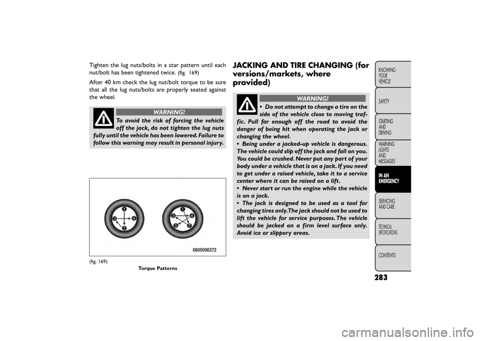
Tighten the lug nuts/bolts in a star pattern until each
nut/bolt has been tightened twice.
(fig. 169)
After 40 km check the lug nut/bolt torque to be sure
that all the lug nuts/bolts are properly seated against
the wheel.
WARNING!
To avoid the risk of forcing the vehicle
off t
he jack, do not tighten the lug nuts
fully until the vehicle has been lowered. Failure to
follow this warning may result in personal injury.
JACKING AND TIRE CHANGING (for
versions/markets, where
provided)
WARNING!
• Do not attempt to change a tire on the
si de
of the vehicle close to moving traf-
fic . Pull far enough off the road to avoid the
danger of being hit when operating the jack or
changing the wheel.
• Being under a jacked-up vehicle is dangerous.
The vehicle could slip off the jack and fall on you.
You could be crushed. Never put any part of your
body under a vehicle that is on a jack. If you need
to get under a raised vehicle, take it to a service
center where it can be raised on a lift .
• Never start or run the engine while the vehicle
is on a jack.
• The jack is designed to be used as a tool for
changing tires only.The jack should not be used to
lift the vehicle for service purposes. The vehicle
should be jacked on a firm level surface only.
Avoid ice or slippery areas.
(fig. 169)
Torque Patterns
283
KNOWING
YOUR
VEHICLE
SAFETY
STARTING
AND
DRIVING
WARNING
LIGHTS
AND
MESSAGES
IN AN
EMERGENCY
SERVICING
AND
CARE
TECHNICAL
SPECIFICATIONS
CONTENTS
Page 292 of 412
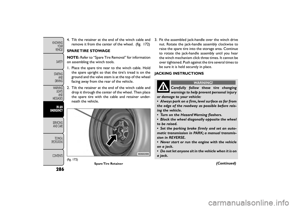
4. Tilt the retainer at the end of the winch cable andremove it from the center of the wheel. (fig. 172)
SPARE TIRE STOWAGE
NOTE: Refer to “Spare Tire Removal” for information
on assembling the winch tools.
1. Place the spare tire near to the winch cable. Hold the spare upright so that the tire's tread is on the
ground and the valve stem is at the top of the wheel
facing away from the rear of the vehicle.
2. Tilt the retainer at the end of the winch cable and drop it through the center of the wheel. Then place
the spare tire with the cable and retainer under-
neath the vehicle. 3. Fit the assembled jack-handle over the winch drive
nut. Rotate the jack-handle assembly clockwise to
raise the spare tire into the storage area. Continue
to rotate the jack-handle assembly until you hear
the winch mechanism click three times. It cannot be
over tightened. Push against the tire several times to
be sure it is held securely in place.
JACKING INSTRUCTIONS
WARNING!
Carefully follow these tire changing
warnin gs
to help prevent personal injury
or damage to your vehicle:
• Always park on a firm, level surface as far from
the edge of the roadway as possible before rais-
ing the vehicle.
• Turn on the Hazard Warning flashers.
• Block the wheel diagonally opposite the wheel
to be raised.
• Set the parking brake firmly and set an auto-
matic transmission in PARK; a manual transmis-
sion in REVERSE.
• Never start or run the engine with the vehicle
on a jack.
• Do not let anyone sit in the vehicle when it is on
a jack.
(Continued)
(fig. 172)Spare Tire Retainer
286
KNOWINGYOUR
VEHICLE
SAFETY
STARTING AND
DRIVING
WARNING LIGHTSAND
MESSAGES
IN AN
EMERGENCY
SER VICING
AND
CARE
TECHNICAL
SPECIFICATIONS
CONTENTS
Page 303 of 412
NOTE:Do not remove foreign objects (e.g., screws or
nails) from the tire.
(C) Injecting Tire Service Kit Sealant Into The
Deflated Tire:
• Always start the engine before turning ON the Tire Service Kit.
NOTE: Manual transmission vehicles must have the
parking brake engaged and the shift lever in NEUTRAL.
• After pressing the Power Button (4), the sealant (white fluid) will flow from the Sealant Bottle (1)
through the Sealant Hose (6) and into the tire.
NOTE: Sealant may leak out through the puncture in
the tire.
If the sealant (white fluid) does not flow within 0
– 10 seconds through the Sealant Hose (6):
1. Press the Power Button (4) to turn Off the Tire Service Kit. Disconnect the Sealant Hose (6) from
the valve stem. Make sure the valve stem is free of
debris. Reconnect the Sealant Hose (6) to the valve
stem. Check that the Mode Select Knob (5) is in the
Sealant Mode position and not Air Mode. Press the
Power Button (4) to turn On the Tire Service Kit. 2. Connect the Power Plug (8) to a different 12 Volt
power outlet in your vehicle or another vehicle, if
available. Make sure the engine is running before
turning ON the Tire Service Kit.
3. The Sealant Bottle (1) may be empty due to previ- ous use. Call for assistance.
NOTE: If the Mode Select Knob (5) is on Air Mode
and the pump is operating, air will dispense from the
Air Pump Hose (7) only, not the Sealant Hose (6).
If the sealant (white fluid) does flow through the
Sealant Hose (6):
1. Continue to operate the pump until sealant is no longer flowing through hose (typically takes 30 - 70
seconds). As the sealant flows through the Sealant
Hose (6), the Pressure Gauge (3) can read as high as
4.8 Bar. The Pressure Gauge (3) will decrease
quickly from approximately 4.8 Bar to the actual tire
pressure when the Sealant Bottle (1) is empty.
2. The pump will start to inject air into the tire immediately after the Sealant Bottle (1) is empty.
Continue to operate the pump and inflate the tire
to the pressure indicated on the tire pressure label
on the driver-side latch pillar (recommended pres-
sure). Check the tire pressure by looking at the
Pressure Gauge (3).
297
KNOWING
YOUR
VEHICLE
SAFETY
STARTING
AND
DRIVING
WARNING
LIGHTS
AND
MESSAGES
IN AN
EMERGENCY
SER VICING
AND
CARE
TECHNICAL
SPECIFICATIONS
CONTENTS
Page 313 of 412
LICENSE PLATE LAMP
1. Push the small locking tab sticking out of the end ofthe lens toward the side of the vehicle and hold it in
that position.
2. Insert a small flat-blade tool between the end of the lens with the locking tab and the surrounding hous-
ing and then pivot the tool to separate the lens from
the housing.
3. Hold the lens with one hand and rotate the bulb's electrical connector ¼ turn counterclockwise with
the other hand and then separate the bulb and
connector assembly from the lens.
4. Remove the bulb from the connector socket and install the replacement bulb.
5. Install the bulb and connector assembly into the lens and rotate the connector ¼ turn clockwise to
lock it in place.
6. Insert the end of the lens without the locking tab into the housing on the liftgate and then push the
opposite end of the lens into the housing, making
sure it locks in the housing.FUSES
WARNING!
• When replacing a blown fuse, always
use an
appropriate replacement fuse
with the same amp rating as the original fuse.
Never replace a fuse with another fuse of higher
amp rating. Never replace a blown fuse with
metal wires or any other material. Failure to use
proper fuses may result in serious personal in-
jury, fire and/or property damage.
• Before replacing a fuse, make sure that the
ignition is off and that all the other services are
switched off and/or disengaged.
• If the replaced fuse blows again, contact an
authorized dealer.
• If a general protection fuse for safety systems
(air bag system, braking system), power unit sys-
tems (engine system, gearbox system) or steering
system blows, contact an authorized dealer.
307
KNOWING
YOUR
VEHICLE
SAFETY
STARTING
AND
DRIVING
WARNING
LIGHTS
AND
MESSAGES
IN AN
EMERGENCY
SER VICING
AND
CARE
TECHNICAL
SPECIFICATIONS
CONTENTS
Page 316 of 412
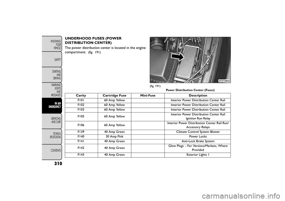
UNDERHOOD FUSES (POWER
DISTRIBUTION CENTER)
The power distribution center is located in the engine
compartment.
(fig. 191)
Cavity Cartridge Fuse Mini-FuseDescription
F101 60 Amp Yellow Interior Power Distribution Center Rail
F102 60 Amp Yellow Interior Power Distribution Center Rail
F103 60 Amp Yellow Interior Power Distribution Center Rail
F105 60 Amp Yellow Interior Power Distribution Center Rail
Ignition Run Relay
F106 60 Amp Yellow Interior Power Distribution Center Rail Run/
Accessory Relays
F139 40 Amp Green Climate Control System Blower
F140 30 Amp Pink Power Locks
F141 40 Amp Green Anti-Lock Brake System
F142 40 Amp Green Glow Plugs – For Versions/Markets, Where
Provided
F143 40 Amp Green Exterior Lights 1
(fig. 191)
Power Distribution Center (Fuses)
310
KNOWINGYOUR
VEHICLE
SAFETY
STARTING AND
DRIVING
WARNING LIGHTSAND
MESSAGES
IN AN
EMERGENCY
SER VICING
AND
CARE
TECHNICAL
SPECIFICATIONS
CONTENTS
Page 319 of 412
SHIFT LEVER OVERRIDE
If a malfunction occurs and the shift lever cannot be
moved out of the PARK position, you can use the
following procedure to temporarily move the shift
lever :
1. Turn the engine OFF.
2. Firmly apply the parking brake.
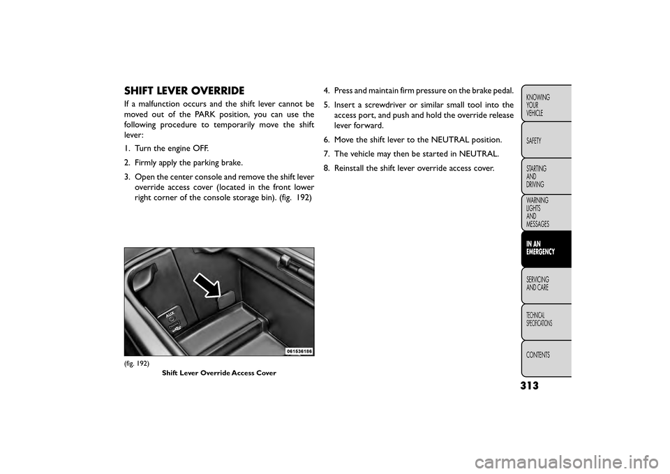
3. Open the center console and remove the shift leveroverride access cover (located in the front lower
right corner of the console storage bin). (fig. 192) 4. Press and maintain firm pressure on the brake pedal.
5. Insert a screwdriver or similar small tool into the
access port, and push and hold the override release
lever forward.
6. Move the shift lever to the NEUTRAL position.
7. The vehicle may then be started in NEUTRAL.
8. Reinstall the shift lever override access cover.
(fig. 192) Shift Lever Override Access Cover
313
KNOWING
YOUR
VEHICLE
SAFETY
STARTING
AND
DRIVING
WARNING
LIGHTS
AND
MESSAGES
IN AN
EMERGENCY
SERVICING
AND
CARE
TECHNICAL
SPECIFICATIONS
CONTENTS
Page 320 of 412
FREEING A STUCK VEHICLE
If your vehicle becomes stuck in mud, sand, or snow, it
can often be moved using a rocking motion. Turn the
steering wheel right and left to clear the area around
the front wheels. Then shift back and forth between
DRIVE and REVERSE (with automatic transmission) or
2nd gear and REVERSE (with manual transmission),
while gently pressing the accelerator. Use the least
amount of accelerator pedal pressure that will maintain
the rocking motion, without spinning the wheels or
racing the engine.
NOTE:Press the "ESC Off" switch, to place the
Electronic Stability Control (ESC) system in
"Partial Off" mode, before rocking the ve-
hicle. Refer to “Electronic Brake Control” in
“Knowing Your Vehicle” for further informa-
tion. Once the vehicle has been freed, press the "ESC
Off" switch again to restore "ESC On" mode.
• Racing the engine or spinning the
wheels may lead to transmission over-
heating and failure. Allow the engine to
idle with the transmission in NEUTRAL for at
least one minute after every five rocking-motion
cycles.This will minimize overheating and reduce
the risk of clutch or transmission failure during
prolonged efforts to free a stuck vehicle.
• When “rocking” a stuck vehicle by shifting be-
tween DRIVE/2nd gear and REVERSE, do not spin
the wheels faster than 24 km/h, or drivetrain
damage may result .
• Revving the engine or spinning the wheels too
fast may lead to transmission overheating and
failure. It can also damage the tires. Do not spin
the wheels above 48 km/h while in gear (no trans-
mission shifting occurring).
314
KNOWING YOUR
VEHICLE
SAFETY
STARTING AND
DRIVING
WARNING LIGHTSAND
MESSAGES
IN AN
EMERGENCY
SER VICING
AND
CARE
TECHNICAL
SPECIFICATIONS
CONTENTS
Page 327 of 412
SERVICING AND CARE
MAINTENANCE SCHEDULE
MAINTENANCE SCHEDULE – GASOLINE
ENGINE
The Scheduled Maintenance services listed in this
manual must be done at the times or mileages specified
to protect your vehicle warranty and ensure the best
vehicle performance and reliability. More frequent
maintenance may be needed for vehicles in severe
operating conditions, such as dusty areas and very
short trip driving. Inspection and service should also be
done anytime a malfunction is suspected.
The oil change indicator system will remind you that it
is time to take your vehicle in for scheduled mainte-
nance.
On Electronic Vehicle Information Center (EVIC)
equipped vehicles “Oil Change Required” will be dis-
played in the EVIC and a single chime will sound,
indicating that an oil change is necessary.NOTE:
•
The oil change indicator message will not
monitor the time since the last oil change.
Change your vehicles oil if it has been 1 year
since your last oil change even if the oil change
indicator message is NOT illuminated.
• Under no circumstances should oil change
intervals exceed 15,000 km or 1 year, which-
ever comes first.
• Rotate the tires at the first sign of irregular
wear.
Your authorized dealer will reset the oil change indica-
tor message after completing the scheduled oil change.
Failure to perform the required mainte-
nance items may result in damage to the
vehicle.
321
KNOWING
YOUR
VEHICLE
SAFETY
STARTING
AND
DRIVING
WARNING
LIGHTS
AND
MESSAGES
IN AN
EMERGENCY
SERVICING
AND C ARE
TECHNICAL
SPECIFICATIONS
CONTENTS