FIAT FREEMONT 2016 1.G Owners Manual
Manufacturer: FIAT, Model Year: 2016, Model line: FREEMONT, Model: FIAT FREEMONT 2016 1.GPages: 412, PDF Size: 3.36 MB
Page 131 of 412
horn three times (on the third attempt ALL doors will
lock and the Passive Entry RKE transmitter can be
locked in the vehicle).
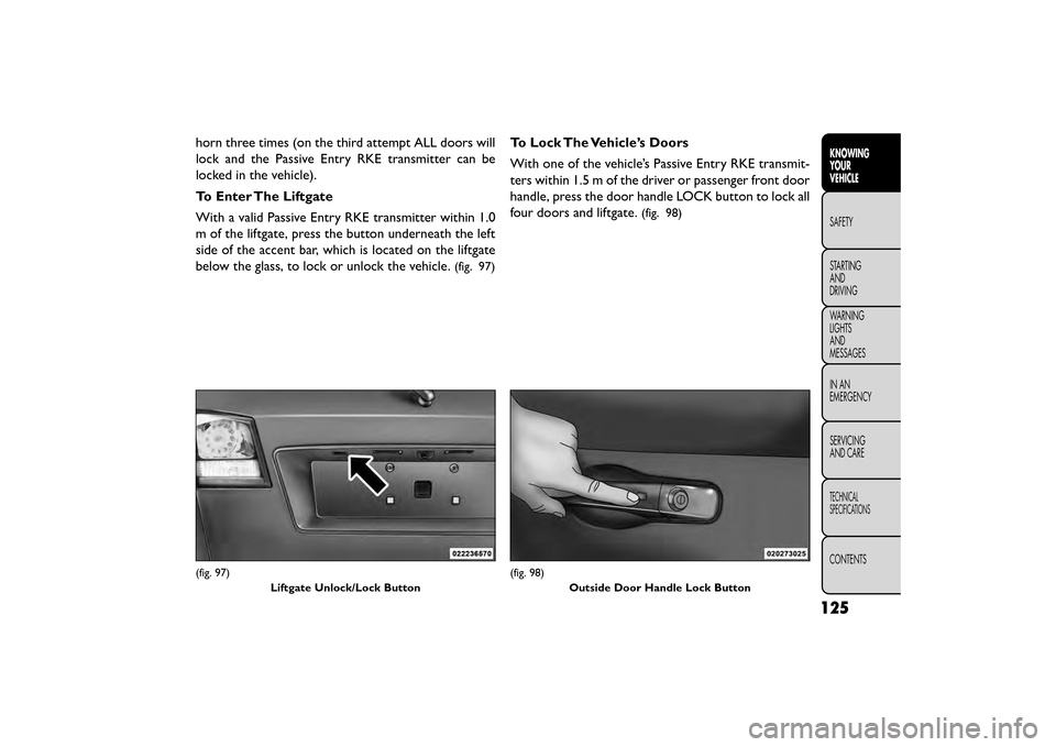
To Enter The Liftgate
With a valid Passive Entry RKE transmitter within 1.0
m of the liftgate, press the button underneath the left
side of the accent bar, which is located on the liftgate
below the glass, to lock or unlock the vehicle.
(fig. 97)
To Lock The Vehicle’s Doors
With one of the vehicle’s Passive Entry RKE transmit-
ters within 1.5 m of the driver or passenger front door
handle, press the door handle LOCK button to lock all
four doors and liftgate.
(fig. 98)
(fig. 97)Liftgate Unlock/Lock Button(fig. 98)Outside Door Handle Lock Button
125
KNOWING
YOUR
VEHICLE
SAFETY
STAR
TING
AND
DRIVING
WARNING
LIGHTS
AND
MESSAGES
IN AN
EMERGENCY
SERVICING
AND CARE
TECHNICAL
SPECIFICATIONS
CONTENTS
Page 132 of 412
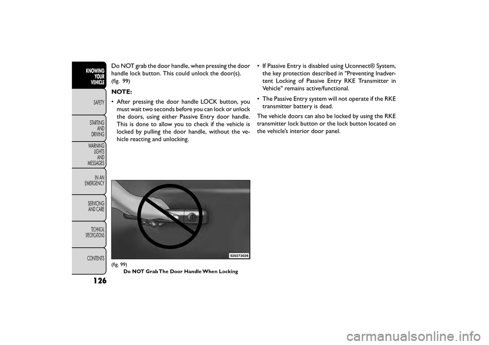
Do NOT grab the door handle, when pressing the door
handle lock button. This could unlock the door(s).
(fig. 99)
NOTE:
• After pressing the door handle LOCK button, youmust wait two seconds before you can lock or unlock
the doors, using either Passive Entry door handle.
This is done to allow you to check if the vehicle is
locked by pulling the door handle, without the ve-
hicle reacting and unlocking. • If Passive Entry is disabled using Uconnect® System,
the key protection described in "Preventing Inadver-
tent Locking of Passive Entry RKE Transmitter in
Vehicle" remains active/functional.
• The Passive Entry system will not operate if the RKE transmitter battery is dead.
The vehicle doors can also be locked by using the RKE
transmitter lock button or the lock button located on
the vehicle’s interior door panel.
(fig. 99) Do NOT Grab The Door Handle When Locking
126
KNOWING YOUR
VEHICLE
SAFETY
STAR
TINGAND
DRIVING
WARNING LIGHTSAND
MESSAGES
IN AN
EMERGENCY
SERVICINGAND CARE
TECHNICAL
SPECIFICATIONS
CONTENTS
Page 133 of 412
WINDOWS
POWER WINDOWS
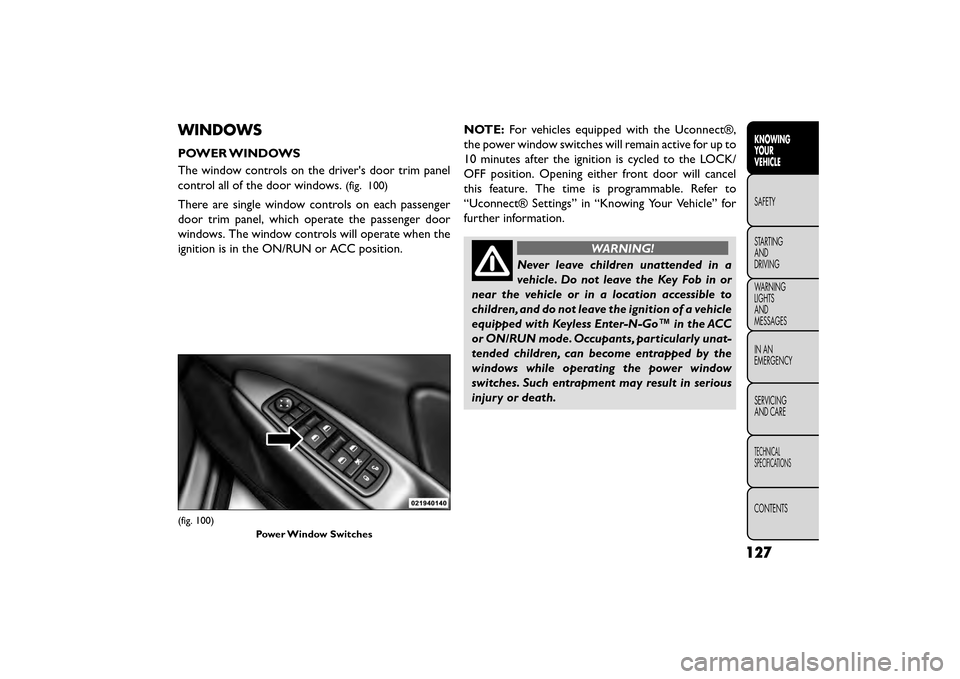
The window controls on the driver's door trim panel
control all of the door windows.
(fig. 100)
There are single window controls on each passenger
door trim panel, which operate the passenger door
windows. The window controls will operate when the
ignition is in the ON/RUN or ACC position.NOTE:
For vehicles equipped with the Uconnect®,
the power window switches will remain active for up to
10 minutes after the ignition is cycled to the LOCK/
OFF position. Opening either front door will cancel
this feature. The time is programmable. Refer to
“Uconnect® Settings” in “Knowing Your Vehicle” for
further information.
WARNING!
Never leave children unattended in a
vehi cle
. Do not leave the Key Fob in or
near the vehicle or in a location accessible to
children, and do not leave the ignition of a vehicle
equipped with Keyless Enter-N-Go™ in the ACC
or ON/RUN mode. Occupants, particularly unat-
tended children, can become entrapped by the
windows while operating the power window
switches. Such entrapment may result in serious
injury or death.
(fig. 100)
Power Window Switches
127
KNOWING
YOUR
VEHICLE
SAFETY
STAR
TING
AND
DRIVING
WARNING
LIGHTS
AND
MESSAGES
IN AN
EMERGENCY
SERVICING
AND CARE
TECHNICAL
SPECIFICATIONS
CONTENTS
Page 134 of 412
AUTO-DOWN FEATURE
The driver's power window switch has an Auto-down
feature. Press the window switch past the first detent,
release, and the window will go down automatically.
To open the window part way, press the window
switch to the first detent and release it when you want
the window to stop.
To stop the window from going all the way down during
the Auto-down operation, pull up on the switch briefly.
AUTO-UP FEATURE WITH ANTI-PINCH
PROTECTION
On some models, the driver and front passenger
power window switches have an Auto-up feature. Pull
the window switch up to the second detent, release,
and the window will go up automatically.
To stop the window from going all the way up during
the Auto-up operation, push down on the switch
briefly.
To close the window part way, pull the window switch
up to the first detent and release it when you want the
window to stop.NOTE:
• If the window runs into any obstacle during Auto-
closure, it will reverse direction and then go back
down. Remove the obstacle and use the window
switch again to close the window.
• Any impact due to rough road conditions may trigger the auto-reverse function unexpectedly during auto-
closure. If this happens, pull the switch lightly to the
first detent and hold to close window manually.
WARNING!
There is no anti-pinch protection when
th e
window is almost closed. To avoid
personal injury, be sure to clear your arms, hands,
fingers, and objects from the window path before
closing the window. Such entrapment may result
in serious injury.
RESET
It may be necessary at some point in time to reactivate
the Auto-up/Auto-down feature. To do so, perform
the following steps:
1. Pull the window switch up to close the window completely and continue to hold the switch up for
an additional two seconds after the window is
closed.
128
KNOWING YOUR
VEHICLE
SAFETY
STAR
TINGAND
DRIVING
WARNING LIGHTSAND
MESSAGES
IN AN
EMERGENCY
SERVICINGAND CARE
TECHNICAL
SPECIFICATIONS
CONTENTS
Page 135 of 412
2. Push the window switch down firmly to the seconddetent to open the window completely and con-
tinue to hold the switch down for an additional two
seconds after the window is fully open.
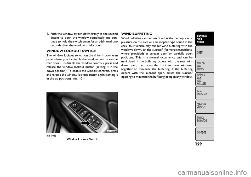
WINDOW LOCKOUT SWITCH
The window lockout switch on the driver's door trim
panel allows you to disable the window control on the
rear doors. To disable the window controls, press and
release the window lockout button (setting it in the
down position). To enable the window controls, press
and release the window lockout button again (setting it
in the up position).
(fig. 101)
WIND BUFFETING
Wind buffeting can be described as the perception of
pressure on the ears or a helicopter-type sound in the
ears. Your vehicle may exhibit wind buffeting with the
windows down, or the sunroof (for versions/markets,
where provided) in certain open or partially open
positions. This is a normal occurrence and can be
minimized. If the buffeting occurs with the rear win-
dows open, then open the front and rear windows
together to minimize the buffeting. If the buffeting
occurs with the sunroof open, adjust the sunroof
opening to minimize the buffeting or open any window.
(fig. 101) Window Lockout Switch
129
KNOWING
YOUR
VEHICLE
SAFETY
STAR
TING
AND
DRIVING
WARNING
LIGHTS
AND
MESSAGES
IN AN
EMERGENCY
SERVICING
AND CARE
TECHNICAL
SPECIFICATIONS
CONTENTS
Page 136 of 412
LIFTGATE
The liftgate can be unlocked or locked pushing the
UNLOCK or LOCK button on the Remote Keyless
Entry (RKE) transmitter, the Keyless Enter-N-Go™
(Passive Entry) LOCK/UNLOCK button underneath
the left side of the accent bar, which is located on the
liftgate below the glass or by activating the power door
lock switch located on either front door trim panel.
For further information on Keyless Enter-N-Go™
(Passive Entry), refer to “Keyless Enter-N-Go™” in
“Things To Know Before Starting Your Vehicle”.
NOTE:The liftgate cannot be unlocked or locked with
the manual door lock plungers on the door trim panels
or the door lock cylinder on the driver's door.
To open the unlocked liftgate, squeeze the handle and
pull the liftgate toward you. Gas props will raise and
support the liftgate in the open position. NOTE:
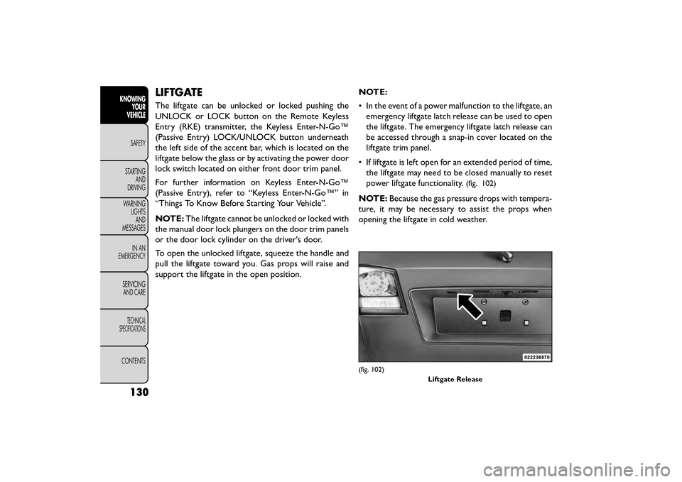
• In the event of a power malfunction to the liftgate, an
emergency liftgate latch release can be used to open
the liftgate. The emergency liftgate latch release can
be accessed through a snap-in cover located on the
liftgate trim panel.
• If liftgate is left open for an extended period of time, the liftgate may need to be closed manually to reset
power liftgate functionality.
(fig. 102)
NOTE: Because the gas pressure drops with tempera-
ture, it may be necessary to assist the props when
opening the liftgate in cold weather.
(fig. 102)
Liftgate Release
130
KNOWINGYOUR
VEHICLE
SAFETY
STAR
TINGAND
DRIVING
WARNING LIGHTSAND
MESSAGES
IN AN
EMERGENCY
SERVICINGAND CARE
TECHNICAL
SPECIFICATIONS
CONTENTS
Page 137 of 412
WARNING!
• Driving with the liftgate open can al-
lo w
poisonous exhaust gases into your
vehicle. These fumes could injure you and your
passengers. Keep the liftgate closed when you are
operating the vehicle.
• If you are required to drive with the liftgate
open, make sure that all windows are closed, and
the blower switch on the climate control is set at
high speed. Do not use the recirculation mode.
CARGO AREA FEATURES
RECHARGEABLE FLASHLIGHT (for
versions/markets, where provided)
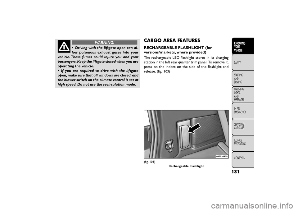
The rechargeable LED flashlight stores in its charging
station in the left rear quarter trim panel. To remove it,
press on the indent on the side of the flashlight and
release.
(fig. 103)
(fig. 103)
Rechargeable Flashlight
131
KNOWING
YOUR
VEHICLE
SAFETY
STAR
TING
AND
DRIVING
WARNING
LIGHTS
AND
MESSAGES
IN AN
EMERGENCY
SERVICING
AND CARE
TECHNICAL
SPECIFICATIONS
CONTENTS
Page 138 of 412
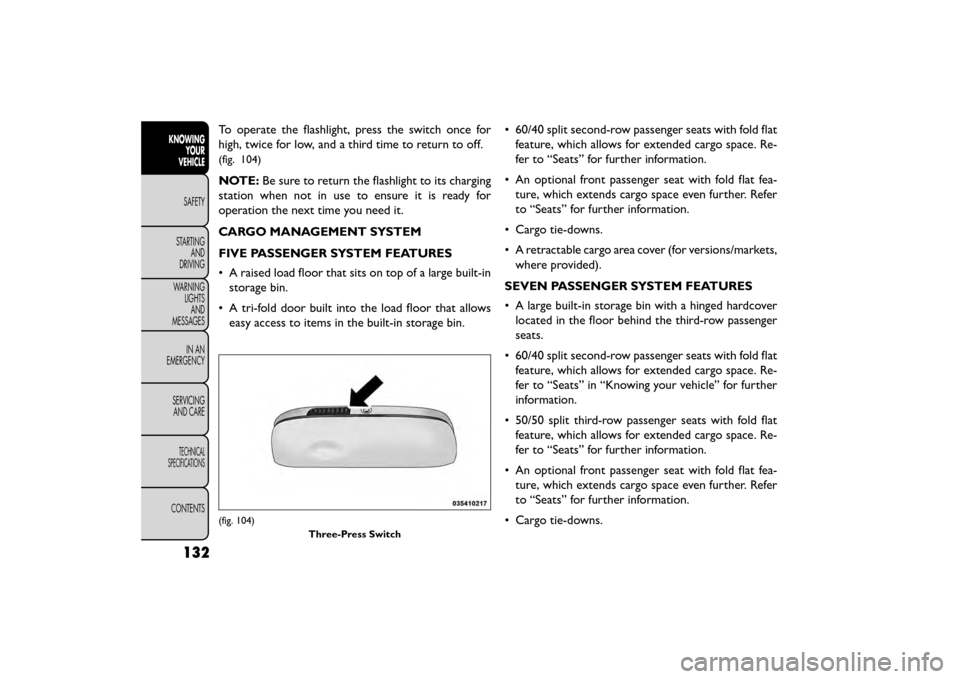
To operate the flashlight, press the switch once for
high, twice for low, and a third time to return to off.
(fig. 104)
NOTE:Be sure to return the flashlight to its charging
station when not in use to ensure it is ready for
operation the next time you need it.
CARGO MANAGEMENT SYSTEM
FIVE PASSENGER SYSTEM FEATURES
• A raised load floor that sits on top of a large built-in storage bin.
• A tri-fold door built into the load floor that allows easy access to items in the built-in storage bin. • 60/40 split second-row passenger seats with fold flat
feature, which allows for extended cargo space. Re-
fer to “Seats” for further information.
• An optional front passenger seat with fold flat fea- ture, which extends cargo space even further. Refer
to “Seats” for further information.
• Cargo tie-downs.
• A retractable cargo area cover (for versions/markets, where provided).
SEVEN PASSENGER SYSTEM FEATURES
• A large built-in storage bin with a hinged hardcover located in the floor behind the third-row passenger
seats.
• 60/40 split second-row passenger seats with fold flat feature, which allows for extended cargo space. Re-
fer to “Seats” in “Knowing your vehicle” for further
information.
• 50/50 split third-row passenger seats with fold flat feature, which allows for extended cargo space. Re-
fer to “Seats” for further information.
• An optional front passenger seat with fold flat fea- ture, which extends cargo space even further. Refer
to “Seats” for further information.
• Cargo tie-downs.
(fig. 104) Three-Press Switch
132
KNOWINGYOUR
VEHICLE
SAFETY
STAR
TINGAND
DRIVING
WARNING LIGHTSAND
MESSAGES
IN AN
EMERGENCY
SERVICINGAND CARE
TECHNICAL
SPECIFICATIONS
CONTENTS
Page 139 of 412
CARGO TIE-DOWNS
WARNING!
Cargo tie-downs are not safe anchors for
a child seat
tether strap. In a sudden stop
or collision, a tie-down could pull loose and allow
the child seat to come loose. A child could be
badly injured. Use only the anchors provided for
child seat tethers.
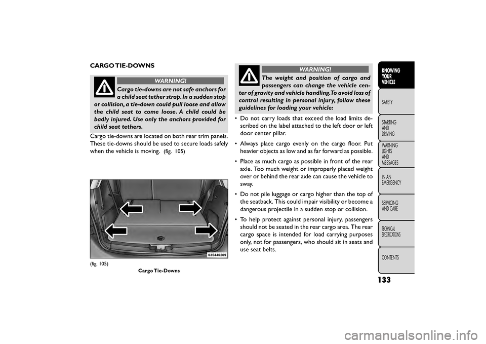
Cargo tie-downs are located on both rear trim panels.
These tie-downs should be used to secure loads safely
when the vehicle is moving.
(fig. 105)
WARNING!
The weight and position of cargo and
passenger s
can change the vehicle cen-
ter of gravity and vehicle handling.To avoid loss of
control resulting in personal injury, follow these
guidelines for loading your vehicle:
• Do not carry loads that exceed the load limits de- scribed on the label attached to the left door or left
door center pillar.
• Always place cargo evenly on the cargo floor. Put heavier objects as low and as far forward as possible.
• Place as much cargo as possible in front of the rear axle. Too much weight or improperly placed weight
over or behind the rear axle can cause the vehicle to
sway.
• Do not pile luggage or cargo higher than the top of the seatback. This could impair visibility or become a
dangerous projectile in a sudden stop or collision.
• To help protect against personal injury, passengers should not be seated in the rear cargo area. The rear
cargo space is intended for load carrying purposes
only, not for passengers, who should sit in seats and
use seat belts.
(fig. 105)
Cargo Tie-Downs
133
KNOWING
YOUR
VEHICLE
SAFETY
STAR
TING
AND
DRIVING
WARNING
LIGHTS
AND
MESSAGES
IN AN
EMERGENCY
SERVICING
AND CARE
TECHNICAL
SPECIFICATIONS
CONTENTS
Page 140 of 412
RETRACTABLE CARGO AREA COVER —
FIVE PASSENGER MODELS (for
versions/markets, where provided)
NOTE:The purpose of this cover is for privacy, not to
secure loads. It will not prevent cargo from shifting or
protect passengers from loose cargo.
The removable retractable cargo area cover mounts in
the cargo area behind the top of the rear seats.
The cover, when extended, covers the cargo area to
keep items out of sight. Notches in the trim panels near
the liftgate opening secure the extended cover in place.
The cover rolls away neatly inside its housing when not
in use. You can also remove the cover from the vehicle
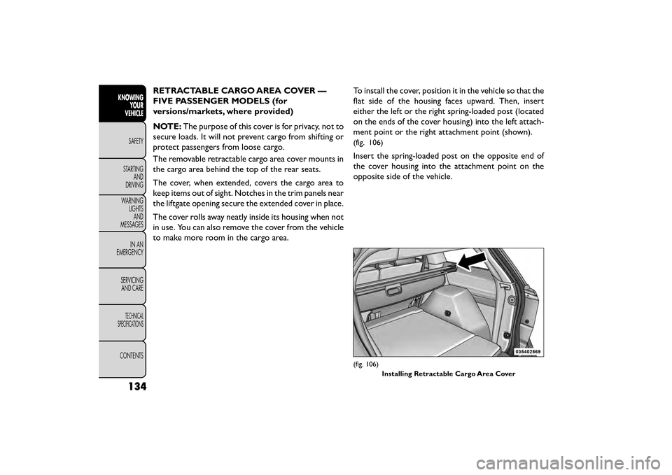
to make more room in the cargo area. To install the cover, position it in the vehicle so that the
flat side of the housing faces upward. Then, insert
either the left or the right spring-loaded post (located
on the ends of the cover housing) into the left attach-
ment point or the right attachment point (shown).
(fig. 106)
Insert the spring-loaded post on the opposite end of
the cover housing into the attachment point on the
opposite side of the vehicle.
(fig. 106)
Installing Retractable Cargo Area Cover
134
KNOWINGYOUR
VEHICLE
SAFETY
STAR
TINGAND
DRIVING
WARNING LIGHTSAND
MESSAGES
IN AN
EMERGENCY
SERVICINGAND CARE
TECHNICAL
SPECIFICATIONS
CONTENTS