stop start FIAT FULLBACK 2017 Owner handbook (in English)
[x] Cancel search | Manufacturer: FIAT, Model Year: 2017, Model line: FULLBACK, Model: FIAT FULLBACK 2017Pages: 312, PDF Size: 12.31 MB
Page 191 of 312
IMPORTANT
149)When you do not wish to drive at a
set speed, turn off the cruise control for
safety.
150)On vehicles with M/T, do not move the
gearshift lever to the “N” (Neutral) position
while driving at a set speed without
depressing the clutch pedal. The engine will
run too fast and might be damaged.
151)Do not use cruise control when driving
conditions will not allow you to stay at the
same speed, such as in heavy traffic or on
roads that are winding, icy, snow-covered,
wet, slippery, on a steep downhill slope.
152)When the set speed driving is
deactivated automatically in any situation
other than those listed above, there may be
a system malfunction. Press the CRUISE
CONTROL ON/OFF switch to turn off the
cruise control and have your vehicle
inspected by a Fiat Dealership.
SPEED LIMITER
The Speed Limiter is a driver assist
function to prevent from exceeding the
speed set by driver while engine power
control.
153)
NOTE If depressing the clutch pedal
(M/T), the Speed Limiter does not
activate.
If the vehicle speed exceeds the set
speed, control state “LIMIT” and the
Speed Limiter’s symbol will blink in the
combination meter.
If the vehicle speed exceeds the set
speed after indicated, control state
“LIMIT” and the beep alert will sound a
certain period of time.
While running without blinked control
state “LIMIT” and the Speed Limiter’s
symbol, if you decrease the set speed
and vehicle speed is more than set
speed, control state “LIMIT” and the
Speed Limiter’s symbol blinking starts
but beep alert is delayed.
In this case, when vehicle speed keeps
exceeding set speed for about
30 seconds after control state “LIMIT”
and the Speed Limiter’s symbol are
blinked, beep alert will sound a certain
period of time.
If the vehicle speeds decreases less
than set speeds, control state “LIMIT”
and the Speed Limiter’s symbol stop
blinking. When beep alert is sounding,
the beep alert also goes off.NOTE However, this gives priority to
audio and visual signal of safety
reasons or driver’s demand. If the set
speed is too lower based on current
shift position, the Speed Limiter may
not limit the vehicle speed to prevent
engine stall.
Speed Limiter control switches
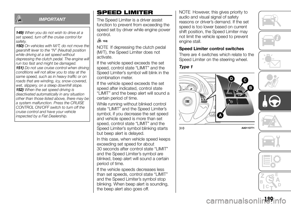
There are 4 switches which relate to the
Speed Limiter on the steering wheel.
Type 1
310AA0113771
189
Page 196 of 312
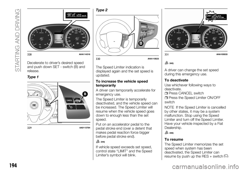
Decelerate to driver’s desired speed
and push down SET - switch (B) and
release.
Type 1Type 2
The Speed Limiter indication is
displayed again and the set speed is
updated.
To increase the vehicle speed
temporarily
A driver can temporarily accelerate for
emergency use.
The Speed Limiter is temporarily
deactivated, and the vehicle speed can
be increased. The Speed Limiter will
resume when the vehicle speed goes
down to enough less than the set
speed.
Put on an accelerator pedal to the
pedal stroke end (over a detent that
makes pedal reaction force bigger
before pedal stroke end).
244)
If vehicle speed exceeds set speed,
control state “LIMIT” and the Speed
Limiter’s symbol will blink.
245)
A driver can change the set speed
during this emergency use.
To deactivate
Use whichever following ways to
deactivate.
Press CANCEL switch
Press the Speed Limiter ON/OFF
switch
NOTE If the Speed Limiter is cancelled
by other states, it may be a system
malfunction. Stop using the Speed
Limiter and turn off the Speed Limiter.
Have your vehicle inspected by a Fiat
Dealership.
246)
To resume
The Speed Limiter memorizes the set
speed when system has been
328AHA114316
329AA0113784
330AHA110523331AHA105033
194
STARTING AND DRIVING
deactivated, the Speed Limiter can
resume by push up the RES + switch(C).
Page 202 of 312
the Multi Communication System
(MCS), the Smartphone Link Display
Audio or the DISPLAY AUDIO. When
you move the gearshift lever or the
selector lever to any other position, the
screen will return to its original
indication.
159)
NOTE Because the rear view camera
has a special lens, the lines on the
ground between parking spaces may
not look parallel on the screen.
NOTE In the following situations, the
screen indication may be difficult to see.
There is no abnormality.
Low light (night time)
When the light of the sun or the light
from a vehicle’s headlamps shines
directly into the lens
If a fluorescent light shines directly
into the lens, the screen indication may
be flicker. There is no abnormality.
NOTE If the camera is hot and is then
cooled by rain or a car wash, the lens
can mist up. This phenomenon does
not indicate a malfunction.
NOTE If the atmospheric temperature
is extremely hot or extremely cold, the
rear view camera images may not be
clear. There is no abnormality.
NOTE If a radio set is installed near the
camera, the rear view camera images
may cause electrical system
interference and the system may stop
functioning properly.NOTE It is not possible to fully see
obstacles when the lens is dirty. If the
lens becomes contaminated by water
droplets, snow, mud, or oil, wipe off the
contamination, taking care not to
scratch the lens.
NOTE Please observe the following
cautions. Ignoring them could lead to a
camera malfunction.
Do not subject the camera to
physical shock such as striking it
strongly or throwing a thing.
Do not adhere organic substances,
waxes, oil remover, and glass cleaner to
the camera. If adhered to them,
immediately wipe off.
Do not splash the camera with
boiling water.
Never spray or splash water on the
camera or around it.
Do not disconnect, disassemble or
modify the camera.
Do not scratch the camera, as this
may cause damage to the rear view
camera images.
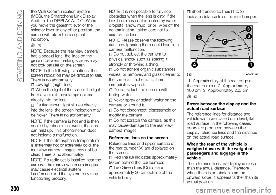
Reference lines on the screen
Reference lines and upper surface of
the rear bumper (A) are displayed on
the screen.
Red line (B) indicates approximately
50 cm behind the rear bumper.
Two Green lines (C) indicate
approximately 20 cm outside of the
vehicle body
Short transverse lines (1 to 3)
indicate distance from the rear bumper.
1. Approximately at the rear edge of
the rear bumper 2. Approximately
100 cm 3. Approximately 200 cm
160)
Errors between the display and the
actual road surface
The reference lines for distance and
vehicle width are based on a level, flat
road surface. In the following cases,
errors are produced between the
display reference lines and the distance
on the actual road surface.
When the rear of the vehicle is
weighed down with the weight of
passengers and luggage in the
vehicle
The reference lines are displayed closer
than the actual distance. Therefore
when there is an obstacle on the
upward slope, it appears farther than its
345AG0027115
200
STARTING AND DRIVING
actual position.
Page 208 of 312
Test Mode
You can check if the system is in the
normal standby state by the following
process. Before operation, stop the
vehicle in a safe place, with good
visibility, where radio waves can be
transmitted and received.
Change to Test Mode
1 — When the ignition switch or the
operation mode is set to “OFF”, set the
ignition switch or the operation mode to
“ON” while pressing the SOS switch.
2 — After setting the ignition switch or
the operation mode to “ON”, perform
Steps 3 and 4 within 10 seconds.
3 — Release your finger from the SOS
switch.
4 — Press the SOS switch 3 or more
times.
5 — After approximately 10 seconds
from Step 2, the red lamp and the
green lamp extinguish. After that, the
buzzer sounds 3 times.
NOTE If the buzzer does not sound,
repeat the process from Step 1.
6 — Approximately 60 seconds later,
the green lamp blinks. If you press the
SOS switch within 20 seconds, the
mode changes to the test mode.
NOTE When the red lamp blinks
instead of the green lamp, move the
vehicle in a safe place, with good
visibility, where radio waves can be
transmitted and received, then repeat
the process from Step 1.Within approximately 20 seconds after
the mode is changed to the test mode,
press the SOS switch for one of the
following periods to select the desired
test type.
10 seconds or more: report test to
the emergency call centre
Less than 10 seconds: test of the
ERA-GLONASS system equipment of
the vehicle
NOTE If you do not press the SOS
switch within approximately
20 seconds, the test mode ends.
If you drive a certain distance in the test
mode, the test mode ends.
Report test to the emergency call
centre
1 — The green lamp illuminates, and
the report test to the emergency call
centre is started.
NOTE If the red lamp illuminates for
approximately 60 seconds, the vehicle
is in a place where radio waves cannot
be transmitted and received. Therefore
you cannot report to the emergency call
centre.
2 — When the green lamp
extinguishes, the test mode is
completed.Test of the ERA-GLONASS system
equipment of the vehicle
1 — After the buzzer sounds once,
press the SOS switch.
Lamp Check: when the buzzer
sounds once and the red lamp and the
green lamp illuminate alternately, they
are working normally.
2 — When the lamps are normal, press
the SOS switch. When the lamps do
not illuminate normally, wait for
approximately 20 seconds.
Speaker Check: when the buzzer
sounds twice and continues sounding,
they are working normally
3 — When the speakers are normal,
press the SOS switch. When the buzzer
does not sound normally, wait for
approximately 20 seconds.
Microphone Check: after the buzzer
sounds 3 times, say something towards
the microphone. If your voice sounds
from the speakers, they are working
normally.
4 — When the microphone is normal,
press the SOS switch. When it does not
operate normally, wait for approximately
20 seconds.
5 — If all check results are normal, the
green lamp illuminates (for
approximately 5 seconds) and the
buzzer sounds once.
266)
6—When the green lamp extinguishes,
206
IN AN EMERGENCY
the test mode is completed.
Page 211 of 312
EMERGENCY
STARTING
267) 268) 269) 270) 271) 272) 273) 274) 275) 276) 277) 278)
279) 280) 281) 282) 283)
If the engine cannot be started because
the battery is weak or dead, the battery
from another vehicle can be used with
jumper cables to start the engine.
1. Get the vehicles close enough so the
jumper cables can reach, but be sure
the vehicles aren’t touching each other.
2. Turn off all lamps, heater and other
electrical loads.
3. Set the parking brake firmly on each
vehicle. Put an automatic transmission
in “P” (PARK) or a manual transmission
in “N” (Neutral). Stop the engine.
4. Make sure battery electrolyte is at the
proper level. Refer to “Battery”.
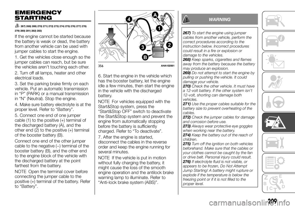
5. Connect one end of one jumper
cable (1) to the positive (+) terminal of
the discharged battery (A), and the
other end (2) to the positive (+) terminal
of the booster battery (B).
Connect one end of the other jumper
cable to the negative (−) terminal of the
booster battery (B), and the other end
to the engine block of the vehicle with
the discharged battery at the point
farthest from the battery.
NOTE Open the terminal cover before
connecting the jumper cable to the
positive (+) terminal of the battery. Refer
to “Battery”.6. Start the engine in the vehicle which
has the booster battery, let the engine
idle a few minutes, then start the engine
in the vehicle with the discharged
battery.
NOTE For vehicles equipped with the
Start&Stop system, press the
“Start&Stop OFF” switch to deactivate
the Start&Stop system and prevent the
engine from automatically stopping
before the battery is sufficiently
charged. Refer to “To deactivate”.
7. After the engine is started,
disconnect the cables in the reverse
order and keep the engine running for
several minutes.
NOTE If the vehicle is put in motion
without fully charging the battery, it
might cause the loss of the smooth
engine operation and the antilock brake
warning lamp to illuminate. Refer to
“Anti-lock brake system (ABS)”.
WARNING
267)To start the engine using jumper
cables from another vehicle, perform the
correct procedures according to the
instruction below. Incorrect procedures
could result in a fire or explosion or
damage to the vehicles.
268)Keep sparks, cigarettes and flames
away from the battery because the battery
may produce an explosion.
269)Do not attempt to start the engine by
pulling or pushing the vehicle. It could
damage your vehicle.
270)Check the other vehicle. It must have
a 12-volt battery. If the other system isn’t
12-volt, shorting can damage both
vehicles.
271)Use the proper cables suitable for the
battery size to prevent overheating of the
cables.
272)Check the jumper cables for damage
and corrosion before use.
273)Always wear protective eye goggles
when working near the battery.
274)Keep the battery out of the reach of
children.
275)Turn off the ignition on both vehicles
beforehand. Make sure that the cables or
your clothes cannot be caught by the fan
or drive belt. Personal injury could result.
276)If electrolyte fluid is not visible, or
appears to be frozen, Do Not Attempt
Jump Starting! A battery might rupture or
explode if the temperature is below the
freezing point or if it is not filled to the
proper level.
356AHA102061
209
Page 212 of 312
277)Electrolyte is corrosive diluted
sulphuric acid. If electrolyte (battery acid)
comes into contact with your hands, eyes,
clothes or the painted surface of your
vehicle, it should be thoroughly flushed
with water. If electrolyte gets in your eyes,
flush them with water immediately and
thoroughly, and get prompt medical
attention.
278)Make sure that the connection is
made to the appointed position (shown in
the illustration). If the connection is made
directly to the negative (−) side of the
battery, the inflammable gases generated
from the battery might catch fire and
explode.
279)When connecting the jumper cables,
do not connect the positive (+) cable to the
negative (−) terminal. Otherwise sparks
might cause explosion of the battery.
280)Use care not to get the jumper cable
caught in the cooling fan or other rotating
part in the engine compartment.
281)Keep the engine of the vehicle giving
assistance running.
282)Battery fluid is poisonous and
corrosive: avoid contact with your skin and
eyes. The battery should be charged in a
well ventilated place, away from naked
flames or possible sources of sparks:
danger of explosion and fire.
283)Do not attempt to charge a frozen
battery: it must be thawed first, otherwise it
may explode. If freezing has occurred, the
battery should be checked by skilled
personnel to make sure that the internal
elements are not damaged and that the
body is not cracked, with the risk of leaking
poisonous and corrosive acid.ENGINE
OVERHEATING
When the engine is overheating,will
blink. If this occurs, take the following
corrective measures:
1. Stop the vehicle in a safe place.
2. Check whether steam is coming from
the engine compartment.
If steam does not come from the engine
compartment: with the engine still
running, raise the bonnet to ventilate
the engine compartment.
NOTE For vehicles equipped with the
Start&Stop system, press the
“Start&Stop OFF” switch to deactivate
the system before stopping the vehicle.
If steam is coming from the engine
compartment: stop the engine, and
when the steam stops, raise the bonnet
to ventilate the engine compartment.
Restart the engine.
284) 285) 286)
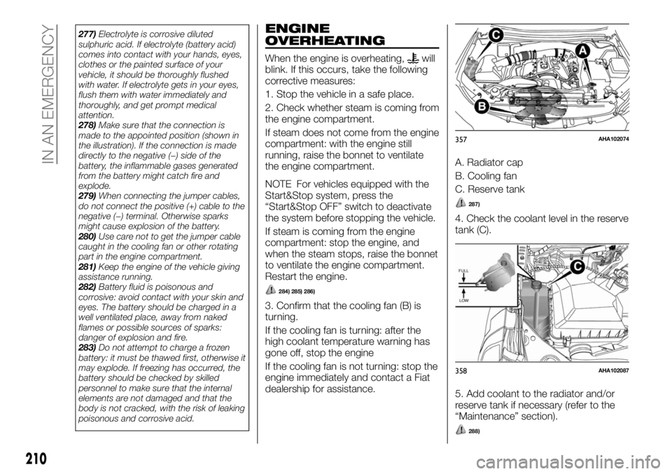
3. Confirm that the cooling fan (B) is
turning.
If the cooling fan is turning: after the
high coolant temperature warning has
gone off, stop the engine
If the cooling fan is not turning: stop the
engine immediately and contact a Fiat
dealership for assistance.A. Radiator cap
B. Cooling fan
C. Reserve tank
287)
4. Check the coolant level in the reserve
tank (C).
5. Add coolant to the radiator and/or
reserve tank if necessary (refer to the
“Maintenance” section).
288)
357AHA102074
358AHA102087
210
IN AN EMERGENCY
Page 223 of 312
NOTE Confirm that the hanger disc is
securely fitted in the wheel disc hole
when the wheel is just lifted off the
ground.
3. After winding up the spare wheel
sufficiently, make sure it is not loose (the
tightening torque should be
approximately 40 Nm (achieved by
applying a force of 200 N at the end of
the wheel nut wrench) then withdraw
the jack handle.
4. Have your damaged tyre repaired as
soon as possible.
315) 316) 317)
To store the tools, jack and jack
handle
Reverse the removing procedure when
storing the jack, jack handle and wheel
nut wrench. Refer to “Tools, jack and
jack handle”.
WARNING
291)Use the jack only to replace wheels
on the vehicle with which it is supplied or
on other vehicles of the same model. Never
use the jack for other purposes, such as
lifting other car models. Never use the jack
to carry out repairs under the vehicle.
Incorrect positioning of the jack may cause
the lifted vehicle to fall. Do not use the jack
for loads higher than those shown on the
label.292)Have the wheel repaired and refitted
as soon as possible. Do not apply grease
to the bolt threads before fitting: they could
come unscrewed.
293)The spare wheel supplied (for
versions/markets, where provided) is
specific for your vehicle. Therefore, it must
not be used on other models. Do not use
spare wheels of other models on your
vehicle. The wheel bolts are specific for
your vehicle: do not use them on different
models and do not use bolts from other
models on your car.
294)Use your hazard lights, warning
triangle, etc. to show that your vehicle is
stationary according to the regulations in
force. Passengers should get out of the
vehicle, particularly if it is heavily loaded,
and wait for the wheel to be changed away
from the traffic. Apply the handbrake. in the
event of a wheel change on a slope or on
unsurfaced roads, put any object as stop
under the wheels.
295)Be sure to apply chocks or blocks to
the correct tyre when jacking up the
vehicle. If the vehicle moves while jacked
up, the jack could slip out of position,
leading to an accident.
296)The pressure should be periodically
checked and maintained at the specified
pressure while the tyre is stowed. Driving
with an insufficient tyre pressure can lead
to an accident. If you have no choice but to
drive with an insufficient tyre pressure,
keep your speed down and inflate the tyre
to the correct pressure as soon as
possible. (Refer to “Tyre inflation
pressures”).297)Set the jack only at the positions
shown here. If the jack is set at a wrong
position, it could dent your vehicle or the
jack might fall over and cause personal
injury.
298)Do not use the jack on a tilted or soft
surface. Otherwise, the jack might slip and
cause personal injury. Always use the jack
on a flat, hard surface. Before setting the
jack, make sure there are no sand or
pebbles under the jack base.
299)Stop jacking up the vehicle as soon
as the tyre is raised off the ground. It is
dangerous to raise the vehicle any higher.
Do not get under your vehicle while using
the jack. Do not bump the raised vehicle or
leave it sitting on the jack for a long time.
Both are very dangerous. Do not use a jack
except the one that came with your
vehicle. The jack should not be used for
any purpose other than to change a tyre.
No one should be in your vehicle when
using the jack. Do not start or run the
engine while your vehicle is on the jack. Do
not turn the raised wheel. The tyres still on
the ground could turn and make your
vehicle fall off the jack.
300)Do not get under your vehicle while
using the jack.
301)Do not bump the raised vehicle or
leave it sitting on the jack for a long time.
Both are very dangerous.
302)Do not use a jack except the one that
came with your vehicle.
303)The jack should not be used for any
purpose other than to change a tyre.
304)No one should be in your vehicle
when using the jack.
305)Do not start or run the engine while
your vehicle is on the jack.
221
Page 226 of 312
NOTE Using any part other than the
designated towing hooks could result in
damage to the vehicle body.
Using a wire rope or metal chain can
result in damage to the vehicle body. It
is best to use a non-metallic rope. If you
use a wire rope or metal chain, wrap it
with cloth at any point where it touches
the vehicle body.
Use care that the tow rope is kept as
horizontal as possible. An angled tow
rope can damage the vehicle body.
Secure the tow rope to the same side
towing hook, to keep the tow rope as
straight as possible.
2. Keep the engine running. If the
engine is not running, perform the
following operation to unlock the
steering wheel.
[Except for vehicles with the keyless
operation system] On vehicles with
manual transmission, turn the ignition
switch to the “ACC” or “ON” position.On vehicles with automatic
transmission, turn the ignition switch to
the “ON” position. [For vehicles with the
keyless operation system] On vehicles
with manual transmission, put the
operation mode in ACC or ON. On
vehicles with automatic transmission,
put the operation mode in ON.
NOTE For vehicles equipped with the
Start&Stop system, press the
“Start&Stop OFF” switch to deactivate
the Start&Stop system before stopping
the vehicle. Refer to “To deactivate”.175) 176)
3. Place the gearshift lever in the “N”
(Neutral) position (manual transmission)
or the selector lever in the “N”
(NEUTRAL) position (automatic
transmission).
4. On 4WD vehicles, set the drive
modes elector to “2H” position.
5. Turn on the hazard warning lamps if
required by law. (Follow the local driving
laws and regulations).
6. During towing make sure that close
contact is maintained between the
drivers of both vehicles, and that the
vehicles travel at low speed.
321) 322) 323)
If your vehicle tows another vehicle
(vehicles with rear towing hook
only)
324) 325) 326) 327) 328) 329)
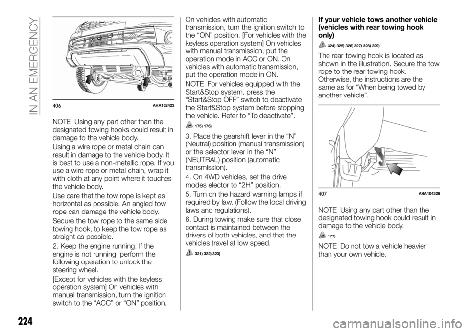
The rear towing hook is located as
shown in the illustration. Secure the tow
rope to the rear towing hook.
Otherwise, the instructions are the
same as for “When being towed by
another vehicle”.
NOTE Using any part other than the
designated towing hook could result in
damage to the vehicle body.
177)
NOTE Do not tow a vehicle heavier
than your own vehicle.
406AHA102423
407AHA104326
224
IN AN EMERGENCY
Page 234 of 312
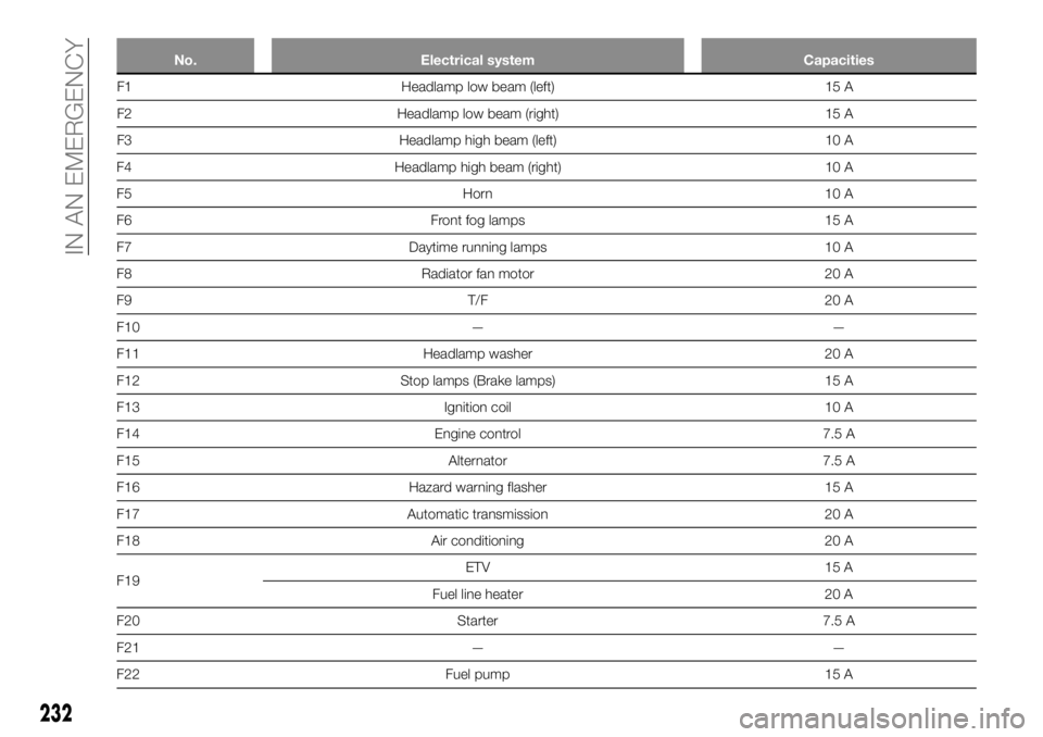
No. Electrical system Capacities
F1 Headlamp low beam (left) 15 A
F2 Headlamp low beam (right) 15 A
F3 Headlamp high beam (left) 10 A
F4 Headlamp high beam (right) 10 A
F5 Horn 10 A
F6 Front fog lamps 15 A
F7 Daytime running lamps 10 A
F8 Radiator fan motor 20 A
F9 T/F 20 A
F10 — —
F11 Headlamp washer 20 A
F12 Stop lamps (Brake lamps) 15 A
F13 Ignition coil 10 A
F14 Engine control 7.5 A
F15 Alternator 7.5 A
F16 Hazard warning flasher 15 A
F17 Automatic transmission 20 A
F18 Air conditioning 20 A
F19ETV 15 A
Fuel line heater 20 A
F20 Starter 7.5 A
F21 — —
F22 Fuel pump 15 A
232
IN AN EMERGENCY
Page 260 of 312
BATTERY
4)
The condition of the battery is very
important for quick starting of the
engine and proper functioning of the
vehicle’s electrical system. Regular
inspection and care are especially
important in cold weather.
375) 376) 377) 378) 379) 380) 381) 382)
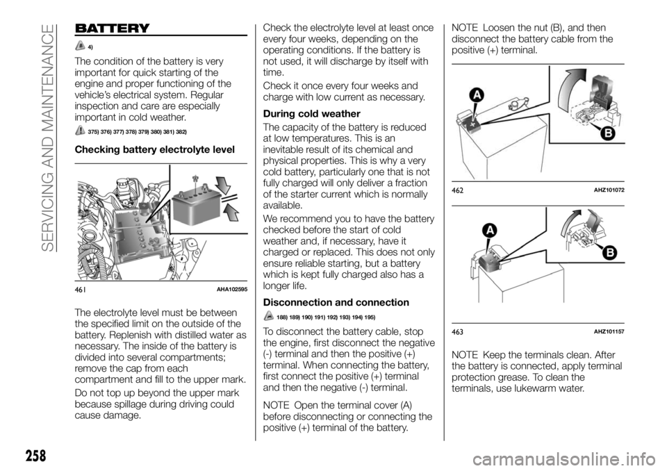
Checking battery electrolyte level
The electrolyte level must be between
the specified limit on the outside of the
battery. Replenish with distilled water as
necessary. The inside of the battery is
divided into several compartments;
remove the cap from each
compartment and fill to the upper mark.
Do not top up beyond the upper mark
because spillage during driving could
cause damage.Check the electrolyte level at least once
every four weeks, depending on the
operating conditions. If the battery is
not used, it will discharge by itself with
time.
Check it once every four weeks and
charge with low current as necessary.
During cold weather
The capacity of the battery is reduced
at low temperatures. This is an
inevitable result of its chemical and
physical properties. This is why a very
cold battery, particularly one that is not
fully charged will only deliver a fraction
of the starter current which is normally
available.
We recommend you to have the battery
checked before the start of cold
weather and, if necessary, have it
charged or replaced. This does not only
ensure reliable starting, but a battery
which is kept fully charged also has a
longer life.
Disconnection and connection
188) 189) 190) 191) 192) 193) 194) 195)
To disconnect the battery cable, stop
the engine, first disconnect the negative
(-) terminal and then the positive (+)
terminal. When connecting the battery,
first connect the positive (+) terminal
and then the negative (-) terminal.
NOTE Open the terminal cover (A)
before disconnecting or connecting the
positive (+) terminal of the battery.NOTE Loosen the nut (B), and then
disconnect the battery cable from the
positive (+) terminal.
NOTE Keep the terminals clean. After
the battery is connected, apply terminal
protection grease. To clean the
terminals, use lukewarm water.
461AHA102595
462AHZ101072
463AHZ101157
258
SERVICING AND MAINTENANCE