technical specifications FIAT IDEA 2007 1.G Repair Manual
[x] Cancel search | Manufacturer: FIAT, Model Year: 2007, Model line: IDEA, Model: FIAT IDEA 2007 1.GPages: 314, PDF Size: 4.78 MB
Page 65 of 314
64
SAFETY
DEVICES
CORRECT USE
OF THE CAR
WARNING
LIGHTS AND
MESSAGES
IN AN
EMERGENCY
CAR
MAINTENANCE
TECHNICAL
SPECIFICATIONS
INDEX
DASHBOARD
AND CONTROLS
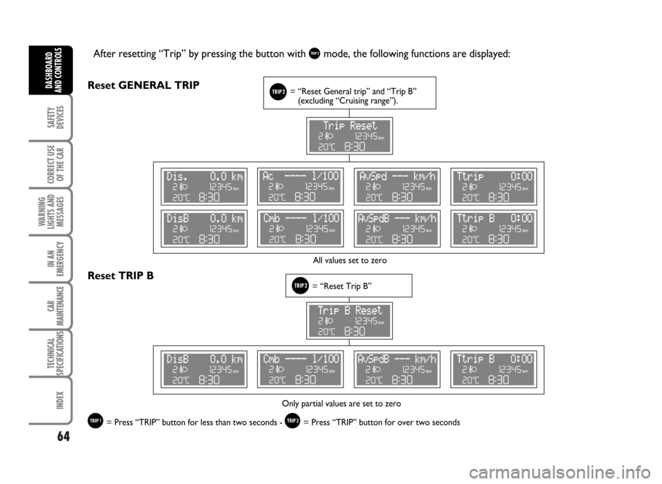
After resetting “Trip” by pressing the button with &mode, the following functions are displayed:
Reset GENERAL TRIP
&= “Reset General trip” and “Trip B”
(excluding “Cruising range”).
&= “Reset Trip B”Reset TRIP B
All values set to zero
Only partial values are set to zero
%= Press “TRIP” button for less than two seconds - &= Press “TRIP” button for over two seconds
Page 66 of 314

65
SAFETY
DEVICES
CORRECT USE
OF THE CAR
WARNING
LIGHTS AND
MESSAGES
IN AN
EMERGENCY
CAR
MAINTENANCE
TECHNICAL
SPECIFICATIONS
INDEX
DASHBOARD
AND CONTROLS
Cruising range= Shows the distance in km (or mi)
that the car can still cover before needing fuel,
assuming that driving conditions are kept unvaried.
The display will show “- - - -” in the following cases:
❒value for range to empty lower than 50 km or fuel
level below 4 litres; in this event before “- - - -”
the message “Warning, limited range” will be
displayed (this message will be displayed also if not
in TRIP COMPUTER mode);
❒in case of car parked with engine running for a
long period, when the car moves off the range to
empty indication will be displayed again.
Travelled distance= shows the km (or miles)
covered from last reset (*).
Average fuel consumption= shows the average
consumption calculated from last reset (*), this value
can be expressed in l/100 km, km/l or mpg.
Instant consumption= shows the fuel consumption
variation updated every second, it can be expressed in
l/100 km or mpg. In case of car parked with engine
running the display will show “- - - -”. When the car
moves off the instant consumption indication will be
displayed again.
Average speed= shows the average speed of the
car in relation with total time elapsed from last reset
(*) and it can be expressed in km/h or in mph.Travel time= time elapsed from last reset (*).
(*) Reset can be:
– “manual”, reset is performed by the driver by
pressing the relevant button (see paragraph
“Control buttons”)
– “automatic”, reset is performed when the travelled
distance reaches 9999.9 km or when Travel time
reaches 99:59 (99 hours and 59 minutes)
– after reconnecting the battery.
IMPORTANT Lacking information, Trip computer
values are displayed with “- - - -”. When normal
operating condition is reset, calculation of different
units will restart regularly. Values displayed before the
failure will not be reset (*).
IMPORTANT After battery disconnection/connection
certain displayed values are equal to “- - - -” until
significant data for calculation are available.
Page 67 of 314
66
SAFETY
DEVICES
CORRECT USE
OF THE CAR
WARNING
LIGHTS AND
MESSAGES
IN AN
EMERGENCY
CAR
MAINTENANCE
TECHNICAL
SPECIFICATIONS
INDEX
DASHBOARD
AND CONTROLS
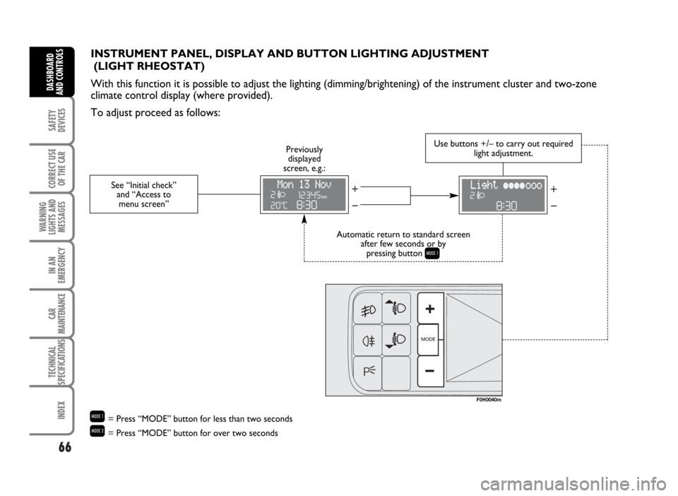
INSTRUMENT PANEL, DISPLAY AND BUTTON LIGHTING ADJUSTMENT
(LIGHT RHEOSTAT)
With this function it is possible to adjust the lighting (dimming/brightening) of the instrument cluster and two-zone
climate control display (where provided).
To adjust proceed as follows:
See “Initial check”
and “Access to
menu screen”
– +– +
Automatic return to standard screen
after few seconds or by
pressing button
Q
Previously
displayed
screen, e.g.:Use buttons +/– to carry out required
light adjustment.
F0H0040m
Q= Press “MODE” button for less than two seconds
R= Press “MODE” button for over two seconds
Page 68 of 314
67
SAFETY
DEVICES
CORRECT USE
OF THE CAR
WARNING
LIGHTS AND
MESSAGES
IN AN
EMERGENCY
CAR
MAINTENANCE
TECHNICAL
SPECIFICATIONS
INDEX
DASHBOARD
AND CONTROLS
If after warning message displaying you smell fuel or see leaks from the fuel
system, do not reset the switch to avoid fire risk.WARNING
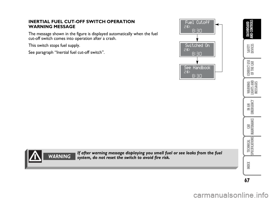
INERTIAL FUEL CUT-OFF SWITCH OPERATION
WARNING MESSAGE
The message shown in the figure is displayed automatically when the fuel
cut-off switch comes into operation after a crash.
This switch stops fuel supply.
See paragraph “Inertial fuel cut-off switch”.
Page 69 of 314
WARNINGAny adjustment of the steering wheel position must be carried out only with the
car stationary and the engine turned off.
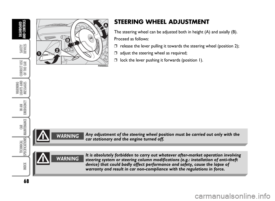
STEERING WHEEL ADJUSTMENT
The steering wheel can be adjusted both in height (A) and axially (B).
Proceed as follows:
❒release the lever pulling it towards the steering wheel (position 2);
❒adjust the steering wheel as required;
❒lock the lever pushing it forwards (position 1).
68
SAFETY
DEVICES
CORRECT USE
OF THE CAR
WARNING
LIGHTS AND
MESSAGES
IN AN
EMERGENCY
CAR
MAINTENANCE
TECHNICAL
SPECIFICATIONS
INDEX
DASHBOARD
AND CONTROLS
F0H0055m
WARNINGIt is absolutely forbidden to carry out whatever after-market operation involving
steering system or steering column modifications (e.g.: installation of anti-theft
device) that could badly affect performance and safety, cause the lapse of
warranty and result in car non-compliance with the regulations in force.
Page 70 of 314
69
SAFETY
DEVICES
CORRECT USE
OF THE CAR
WARNING
LIGHTS AND
MESSAGES
IN AN
EMERGENCY
CAR
MAINTENANCE
TECHNICAL
SPECIFICATIONS
INDEX
DASHBOARD
AND CONTROLS
F0H0041m
F0H0042m
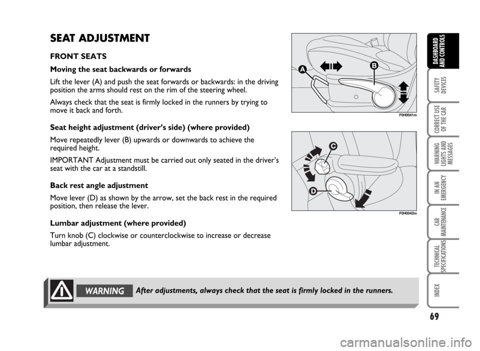
SEAT ADJUSTMENT
FRONT SEATS
Moving the seat backwards or forwards
Lift the lever (A) and push the seat forwards or backwards: in the driving
position the arms should rest on the rim of the steering wheel.
Always check that the seat is firmly locked in the runners by trying to
move it back and forth.
Seat height adjustment (driver’s side) (where provided)
Move repeatedly lever (B) upwards or downwards to achieve the
required height.
IMPORTANT Adjustment must be carried out only seated in the driver’s
seat with the car at a standstill.
Back rest angle adjustment
Move lever (D) as shown by the arrow, set the back rest in the required
position, then release the lever.
Lumbar adjustment (where provided)
Turn knob (C) clockwise or counterclockwise to increase or decrease
lumbar adjustment.
After adjustments, always check that the seat is firmly locked in the runners.WARNING
Page 71 of 314
70
SAFETY
DEVICES
CORRECT USE
OF THE CAR
WARNING
LIGHTS AND
MESSAGES
IN AN
EMERGENCY
CAR
MAINTENANCE
TECHNICAL
SPECIFICATIONS
INDEX
DASHBOARD
AND CONTROLS
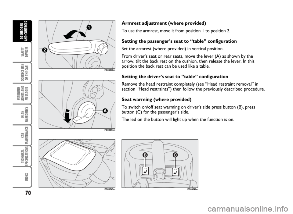
Armrest adjustment (where provided)
To use the armrest, move it from position 1 to position 2.
Setting the passenger’s seat to “table” configuration
Set the armrest (where provided) in vertical position.
From driver’s seat or rear seats, move the lever (A) as shown by the
arrow, tilt the back rest on the cushion, then release the lever. In this
position the back rest can be used like a table.
Setting the driver’s seat to “table” configuration
Remove the head restraint completely (see “Head restraint removal” in
section “Head restraints”) then follow the previously described procedure.
Seat warming (where provided)
To switch on/off seat warming on driver’s side press button (B), press
button (C) for the passenger’s side.
The led on the button will light up when the function is on.
F0H0043m
F0H0044m
F0H0045mF0H0046m
Page 72 of 314
71
SAFETY
DEVICES
CORRECT USE
OF THE CAR
WARNING
LIGHTS AND
MESSAGES
IN AN
EMERGENCY
CAR
MAINTENANCE
TECHNICAL
SPECIFICATIONS
INDEX
DASHBOARD
AND CONTROLS
F0H0047m
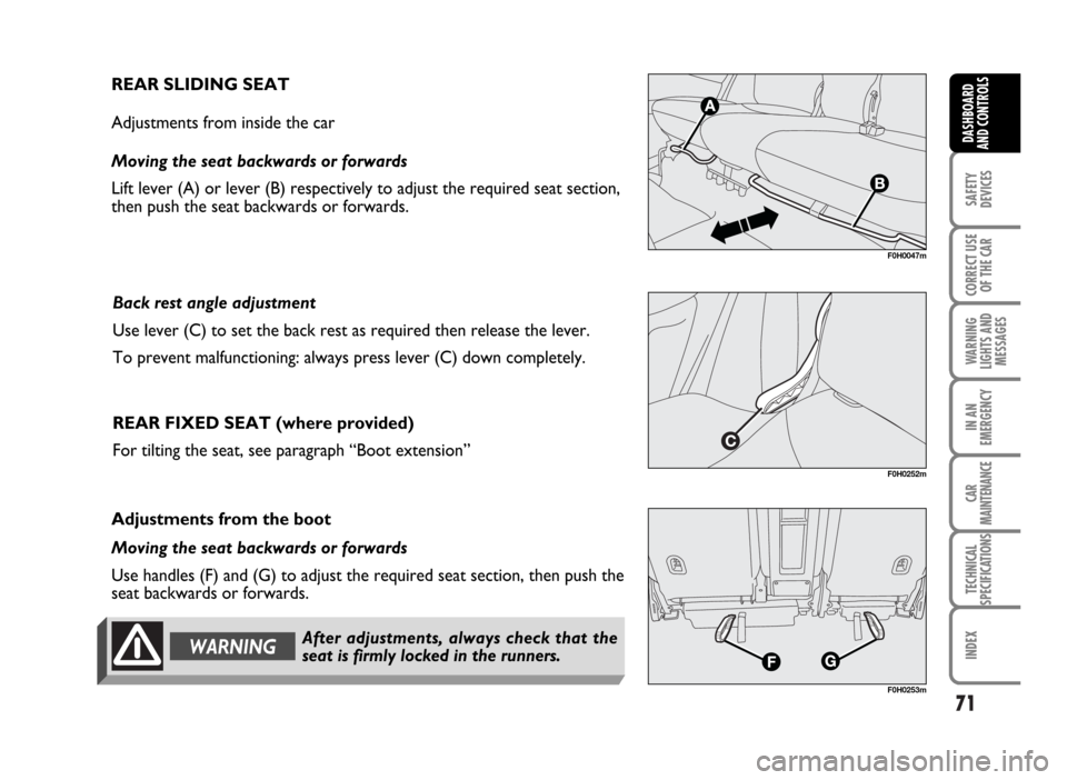
REAR SLIDING SEAT
Adjustments from inside the car
Moving the seat backwards or forwards
Lift lever (A) or lever (B) respectively to adjust the required seat section,
then push the seat backwards or forwards.
Back rest angle adjustment
Use lever (C) to set the back rest as required then release the lever.
To prevent malfunctioning: always press lever (C) down completely.
REAR FIXED SEAT (where provided)
For tilting the seat, see paragraph “Boot extension”
F0H0252m
F0H0253m
Adjustments from the boot
Moving the seat backwards or forwards
Use handles (F) and (G) to adjust the required seat section, then push the
seat backwards or forwards.
WARNINGAfter adjustments, always check that the
seat is firmly locked in the runners.
Page 73 of 314
72
SAFETY
DEVICES
CORRECT USE
OF THE CAR
WARNING
LIGHTS AND
MESSAGES
IN AN
EMERGENCY
CAR
MAINTENANCE
TECHNICAL
SPECIFICATIONS
INDEX
DASHBOARD
AND CONTROLS
F0H0049m
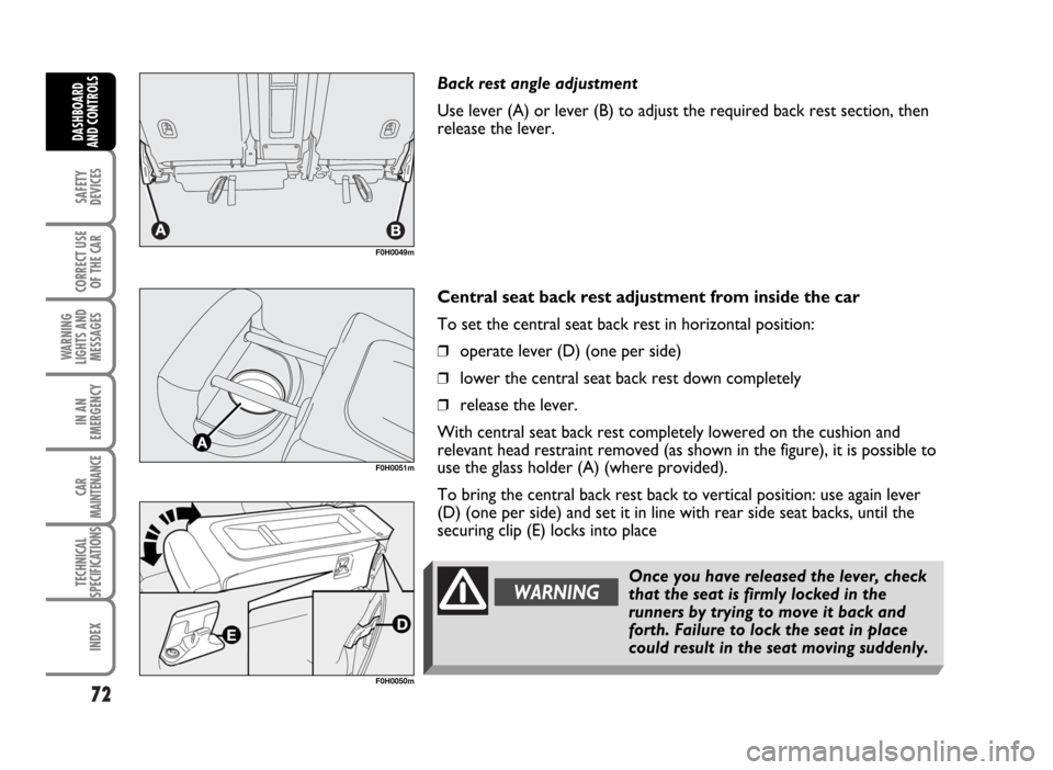
Back rest angle adjustment
Use lever (A) or lever (B) to adjust the required back rest section, then
release the lever.
Central seat back rest adjustment from inside the car
To set the central seat back rest in horizontal position:
❒operate lever (D) (one per side)
❒lower the central seat back rest down completely
❒release the lever.
With central seat back rest completely lowered on the cushion and
relevant head restraint removed (as shown in the figure), it is possible to
use the glass holder (A) (where provided).
To bring the central back rest back to vertical position: use again lever
(D) (one per side) and set it in line with rear side seat backs, until the
securing clip (E) locks into place
F0H0051m
Once you have released the lever, check
that the seat is firmly locked in the
runners by trying to move it back and
forth. Failure to lock the seat in place
could result in the seat moving suddenly.
WARNING
F0H0050m
Page 74 of 314
73
SAFETY
DEVICES
CORRECT USE
OF THE CAR
WARNING
LIGHTS AND
MESSAGES
IN AN
EMERGENCY
CAR
MAINTENANCE
TECHNICAL
SPECIFICATIONS
INDEX
DASHBOARD
AND CONTROLS
For maximum safety, keep the back of your seat upright, lean back into it and
make sure the seat belt fits closely across your hips.WARNING
F0H0255m
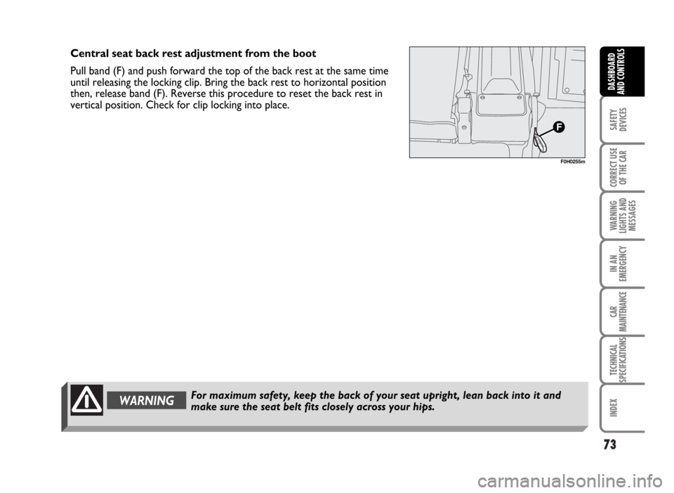
Central seat back rest adjustment from the boot
Pull band (F) and push forward the top of the back rest at the same time
until releasing the locking clip. Bring the back rest to horizontal position
then, release band (F). Reverse this procedure to reset the back rest in
vertical position. Check for clip locking into place.