window FIAT IDEA 2007 1.G Owners Manual
[x] Cancel search | Manufacturer: FIAT, Model Year: 2007, Model line: IDEA, Model: FIAT IDEA 2007 1.GPages: 314, PDF Size: 4.78 MB
Page 5 of 314
4
SAFETY
DEVICES
CORRECT USE
OF THE CAR
WARNING
LIGHTS AND
MESSAGES
IN AN
EMERGENCY
CAR
MAINTENANCE
TECHNICAL
SPECIFICATIONS
INDEX
DASHBOARD
AND CONTROLSSYMBOLS ............................................................................... 5
THE FIAT CODE SYSTEM ................................................. 5
KEY KIT AND DOOR LOCKING .................................. 7
IGNITION SWITCH ............................................................ 20
DASHBOARD........................................................................ 21
INSTRUMENT PANEL ....................................................... 24
INSTRUMENTS ..................................................................... 25
MULTIFUNCTION DISPLAY ........................................... 27
RECONFIGURABLE MULTIFUNCTION DISPLAY ... 35
STEERING WHEEL ADJUSTMENT ................................ 68
SEAT ADJUSTMENT .......................................................... 69
HEAD RESTRAINTS ............................................................ 76
REARVIEW MIRRORS ......................................................... 78
HEATING/CLIMATE
CONTROL SYSTEM ........................................................... 80
HEATING AND VENTILATION ...................................... 82
MANUAL CLIMATE CONTROL SYSTEM ................... 85
AUTOMATIC TWO-ZONE CLIMATE CONTROL
SYSTEM .................................................................................. 89
EXTERNAL LIGHTS............................................................. 100
WINDOW WASHING ....................................................... 104
CRUISE CONTROL ............................................................ 108CEILING LIGHTS ................................................................. 111
LIGHT CONTROL BUTTONS ......................................... 114
INERTIAL FUEL CUT-OFF
SWITCH.................................................................................. 116
INTERIOR FITTINGS ......................................................... 117
SMOKERS’ KIT ...................................................................... 122
SUNROOF.............................................................................. 123
POWER WINDOWS ......................................................... 125
REAR WINDOW WINDERS ............................................ 128
BOOT ...................................................................................... 128
BONNET ................................................................................ 134
ROOF RACK/SKI RACK .................................................... 136
HEADLIGHTS ........................................................................ 136
ABS SYSTEM ......................................................................... 138
EOBD SYSTEM ..................................................................... 140
SOUND SYSTEM .................................................................. 141
ACCESSORIES PURCHASED BY THE OWNER ......... 143
“DUALDRIVE” ELECTRIC POWER
STEERING SYSTEM ............................................................. 144
PARKING SENSORS ........................................................... 146
AT THE FILLING STATION ............................................. 148
PROTECTING THE ENVIRONMENT ............................ 150
D D
A A
S S
H H
B B
O O
A A
R R
D D
A A
N N
D D
C C
O O
N N
T T
R R
O O
L L
S S
Page 17 of 314
DEAD LOCK DEVICE (where provided)
This safety device enables to inhibit:
❒door internal handles;
❒door locking/unlocking buttons set on the
dashboard;
16
SAFETY
DEVICES
CORRECT USE
OF THE CAR
WARNING
LIGHTS AND
MESSAGES
IN AN
EMERGENCY
CAR
MAINTENANCE
TECHNICAL
SPECIFICATIONS
INDEX
DASHBOARD
AND CONTROLS
Once the dead lock device has been actuated, doors cannot be opened from inside
the car in any way whatsoever. For this reason, make sure there are no persons left
inside the car.WARNING
thus hindering doors opening from inside the
passenger’s compartment in case of attempt to break-
into (e.g. window breaking).
Page 21 of 314
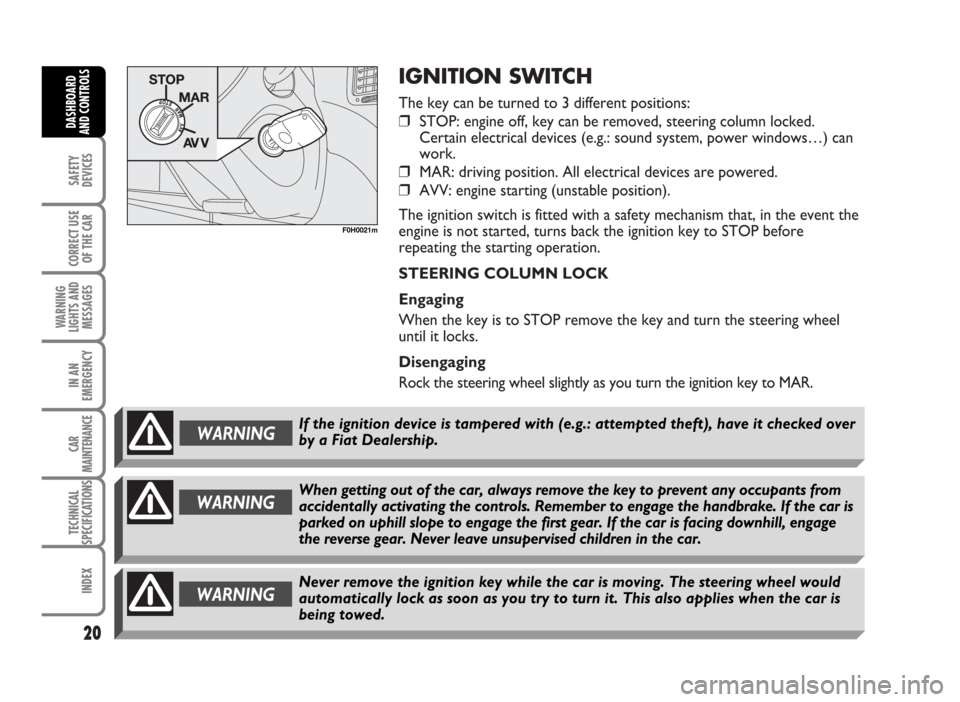
IGNITION SWITCH
The key can be turned to 3 different positions:
❒STOP: engine off, key can be removed, steering column locked.
Certain electrical devices (e.g.: sound system, power windows…) can
work.
❒MAR: driving position. All electrical devices are powered.
❒AVV: engine starting (unstable position).
The ignition switch is fitted with a safety mechanism that, in the event the
engine is not started, turns back the ignition key to STOP before
repeating the starting operation.
STEERING COLUMN LOCK
Engaging
When the key is to STOP remove the key and turn the steering wheel
until it locks.
Disengaging
Rock the steering wheel slightly as you turn the ignition key to MAR.
20
SAFETY
DEVICES
CORRECT USE
OF THE CAR
WARNING
LIGHTS AND
MESSAGES
IN AN
EMERGENCY
CAR
MAINTENANCE
TECHNICAL
SPECIFICATIONS
INDEX
DASHBOARD
AND CONTROLS
Never remove the ignition key while the car is moving. The steering wheel would
automatically lock as soon as you try to turn it. This also applies when the car is
being towed.WARNING
WARNINGWhen getting out of the car, always remove the key to prevent any occupants from
accidentally activating the controls. Remember to engage the handbrake. If the car is
parked on uphill slope to engage the first gear. If the car is facing downhill, engage
the reverse gear. Never leave unsupervised children in the car.
F0H0021m
If the ignition device is tampered with (e.g.: attempted theft), have it checked over
by a Fiat Dealership.WARNING
Page 80 of 314
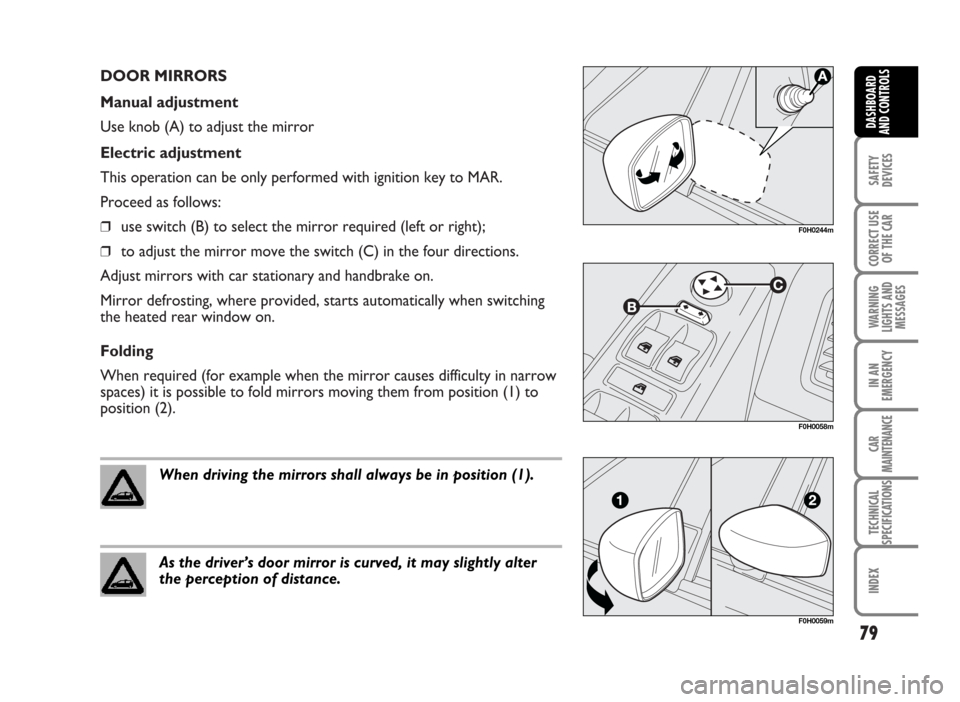
DOOR MIRRORS
Manual adjustment
Use knob (A) to adjust the mirror
Electric adjustment
This operation can be only performed with ignition key to MAR.
Proceed as follows:
❒use switch (B) to select the mirror required (left or right);
❒to adjust the mirror move the switch (C) in the four directions.
Adjust mirrors with car stationary and handbrake on.
Mirror defrosting, where provided, starts automatically when switching
the heated rear window on.
Folding
When required (for example when the mirror causes difficulty in narrow
spaces) it is possible to fold mirrors moving them from position (1) to
position (2).
79
SAFETY
DEVICES
CORRECT USE
OF THE CAR
WARNING
LIGHTS AND
MESSAGES
IN AN
EMERGENCY
CAR
MAINTENANCE
TECHNICAL
SPECIFICATIONS
INDEX
DASHBOARD
AND CONTROLS
F0H0058m
F0H0059m
When driving the mirrors shall always be in position (1).
As the driver’s door mirror is curved, it may slightly alter
the perception of distance.
F0H0244m
Page 81 of 314
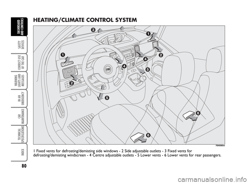
HEATING/CLIMATE CONTROL SYSTEM
80
SAFETY
DEVICES
CORRECT USE
OF THE CAR
WARNING
LIGHTS AND
MESSAGES
IN AN
EMERGENCY
CAR
MAINTENANCE
TECHNICAL
SPECIFICATIONS
INDEX
DASHBOARD
AND CONTROLS
1 Fixed vents for defrosting/demisting side windows - 2 Side adjustable outlets - 3 Fixed vents for
defrosting/demisting windscreen - 4 Centre adjustable outlets - 5 Lower vents - 6 Lower vents for rear passengers.
F0H0060m
Page 82 of 314
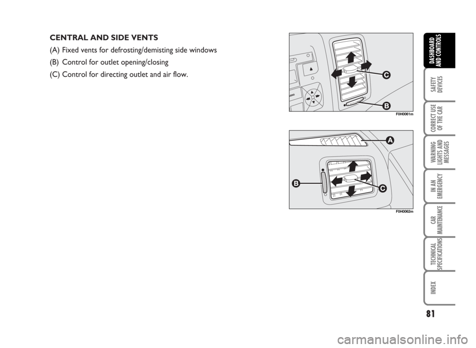
CENTRAL AND SIDE VENTS
(A) Fixed vents for defrosting/demisting side windows
(B) Control for outlet opening/closing
(C) Control for directing outlet and air flow.
81
SAFETY
DEVICES
CORRECT USE
OF THE CAR
WARNING
LIGHTS AND
MESSAGES
IN AN
EMERGENCY
CAR
MAINTENANCE
TECHNICAL
SPECIFICATIONS
INDEX
DASHBOARD
AND CONTROLS
F0H0061m
F0H0062m
Page 83 of 314
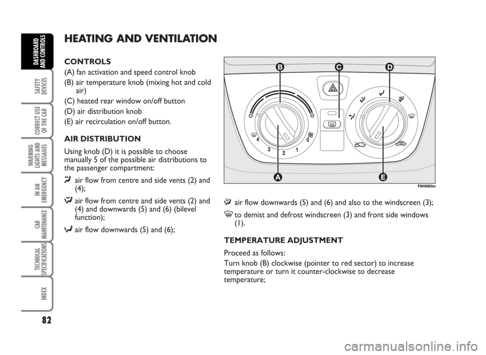
CONTROLS
(A) fan activation and speed control knob
(B) air temperature knob (mixing hot and cold
air)
(C) heated rear window on/off button
(D) air distribution knob
(E) air recirculation on/off button.
AIR DISTRIBUTION
Using knob (D) it is possible to choose
manually 5 of the possible air distributions to
the passenger compartment:
«air flow from centre and side vents (2) and
(4);
Δair flow from centre and side vents (2) and
(4) and downwards (5) and (6) (bilevel
function);
≈air flow downwards (5) and (6);
HEATING AND VENTILATION
ƒair flow downwards (5) and (6) and also to the windscreen (3);
-to demist and defrost windscreen (3) and front side windows
(1).
TEMPERATURE ADJUSTMENT
Proceed as follows:
Turn knob (B) clockwise (pointer to red sector) to increase
temperature or turn it counter-clockwise to decrease
temperature;
82
SAFETY
DEVICES
CORRECT USE
OF THE CAR
WARNING
LIGHTS AND
MESSAGES
IN AN
EMERGENCY
CAR
MAINTENANCE
TECHNICAL
SPECIFICATIONS
INDEX
DASHBOARD
AND CONTROLS
F0H0063m
Page 84 of 314
FAN SPEED ADJUSTMENT
Proceed as follows:
❒open completely central (4) and side (2) vents;
❒turn knob (B) to the blue sector;
❒set (A) to the required speed;
❒set knob (D) to «;
❒set knob (E) to Úto turn air recirculation offRECIRCULATION
Set knob (E) to ….
This function is particularly useful when the outside air
is heavily polluted (in a traffic jam, tunnel, etc.).
However, it is better not to use it for long periods,
especially if there are several people in the car to
prevent window steaming up.
IMPORTANT The inside air recirculation system
makes it possible to reach the required “heating” or
“cooling” conditions faster. Do not use the air
recirculation function on rainy/cold days as it would
considerably increase the possibility of the windows
misting inside.
83
SAFETY
DEVICES
CORRECT USE
OF THE CAR
WARNING
LIGHTS AND
MESSAGES
IN AN
EMERGENCY
CAR
MAINTENANCE
TECHNICAL
SPECIFICATIONS
INDEX
DASHBOARD
AND CONTROLS
Page 85 of 314
QUICK HEATING
Proceed as follows:
❒close all dashboard vents;
❒turn knob (B) to the red sector;
❒turn knob (A) to 4 -;
❒turn knob (D) to ≈.
QUICK WINDSCREEN AND FRONT SIDE
WINDOW DEMISTING/DEFROSTING
Proceed as follows:
❒turn knob (B) to the red sector;
❒turn knob (A) to 4 -;
❒turn knob (D) to -;
❒set knob (E) to Uto turn air recirculation off.
After demisting/defrosting, operate normal controls to
restore the required comfort.Preventive demisting procedure
In the event of considerable outside moisture and/or
rain and/or considerable differences in temperature
inside and outside the passenger compartment,
perform the following preventive demisting procedure:
❒set knob (E) to Uto turn air recirculation off;
❒knob pointer B in the red section;
❒turn knob (A) to 2;
❒turn knob (D) to -or to ƒif the windows do
not mist up.
REAR WINDOW AND ELECTRIC DOOR
MIRROR DEMISTING/DEFROSTING
(where provided)
Press button (C) to turn this function on. When this
function is on, the button led turns on.
This function is timed and switches off automatically
after the preset time. To cut out this function press
again button (C).
IMPORTANT Do not apply stickers on the inside of
the rear window over the heating filaments to avoid
damage that might cause it to stop working properly.
84
SAFETY
DEVICES
CORRECT USE
OF THE CAR
WARNING
LIGHTS AND
MESSAGES
IN AN
EMERGENCY
CAR
MAINTENANCE
TECHNICAL
SPECIFICATIONS
INDEX
DASHBOARD
AND CONTROLS
Page 86 of 314
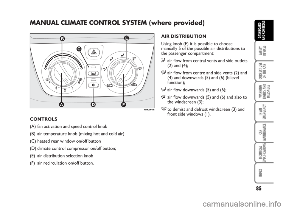
CONTROLS
(A) fan activation and speed control knob
(B) air temperature knob (mixing hot and cold air)
(C) heated rear window on/off button
(D) climate control compressor on/off button;
(E) air distribution selection knob
(F) air recirculation on/off button.
MANUAL CLIMATE CONTROL SYSTEM (where provided)
AIR DISTRIBUTION
Using knob (E) it is possible to choose
manually 5 of the possible air distributions to
the passenger compartment:
«air flow from central vents and side outlets
(2) and (4);
Δair flow from centre and side vents (2) and
(4) and downwards (5) and (6) (bilevel
function);
≈air flow downwards (5) and (6);
ƒair flow downwards (5) and (6) and also to
the windscreen (3);
-to demist and defrost windscreen (3) and
front side windows (1).
85
SAFETY
DEVICES
CORRECT USE
OF THE CAR
WARNING
LIGHTS AND
MESSAGES
IN AN
EMERGENCY
CAR
MAINTENANCE
TECHNICAL
SPECIFICATIONS
INDEX
DASHBOARD
AND CONTROLS
F0H0064m