display FIAT IDEA 2008 1.G User Guide
[x] Cancel search | Manufacturer: FIAT, Model Year: 2008, Model line: IDEA, Model: FIAT IDEA 2008 1.GPages: 210, PDF Size: 3.64 MB
Page 29 of 210
28
SAFETY
DEVICES
CORRECT USE
OF THE CAR
WARNING
LIGHTS AND
MESSAGES
IN AN
EMERGENCY
CAR
MAINTENANCE
TECHNICAL
SPECIFICATIONS
INDEX
DASHBOARD
AND CONTROLS
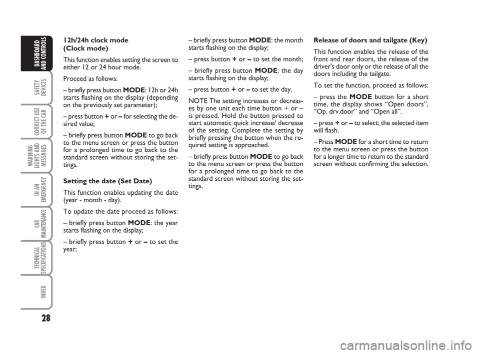
Release of doors and tailgate (Key)
This function enables the release of the
front and rear doors, the release of the
driver's door only or the release of all the
doors including the tailgate.
To set the function, proceed as follows:
– press the MODEbutton for a short
time, the display shows “Open doors”,
“Op. drv.door” and “Open all”.
– press +or –to select; the selected item
will flash.
– Press MODEfor a short time to return
to the menu screen or press the button
for a longer time to return to the standard
screen without confirming the selection. – briefly press button MODE: the month
starts flashing on the display;
– press button +or –to set the month;
– briefly press button MODE: the day
starts flashing on the display;
– press button +or –to set the day.
NOTE The setting increases or decreas-
es by one unit each time button + or –
is pressed. Hold the button pressed to
start automatic quick increase/ decrease
of the setting. Complete the setting by
briefly pressing the button when the re-
quired setting is approached.
– briefly press button MODEto go back
to the menu screen or press the button
for a prolonged time to go back to the
standard screen without storing the set-
tings. 12h/24h clock mode
(Clock mode)
This function enables setting the screen to
either 12 or 24 hour mode.
Proceed as follows:
– briefly press button MODE: 12h or 24h
starts flashing on the display (depending
on the previously set parameter);
– press button +or –for selecting the de-
sired value;
– briefly press button MODEto go back
to the menu screen or press the button
for a prolonged time to go back to the
standard screen without storing the set-
tings.
Setting the date (Set Date)
This function enables updating the date
(year - month - day).
To update the date proceed as follows:
– briefly press button MODE: the year
starts flashing on the display;
– briefly press button +or –to set the
year;
001-035 idea GB 1 ed 10-07-2008 8:27 Pagina 28
Page 30 of 210
29
SAFETY
DEVICES
CORRECT USE
OF THE CAR
WARNING
LIGHTS AND
MESSAGES
IN AN
EMERGENCY
CAR
MAINTENANCE
TECHNICAL
SPECIFICATIONS
INDEX
DASHBOARD
AND CONTROLS
Unit - “distance” (Dist. unit)
With this function it is possible to set the
units for distance covered (km or mi).
To set the required unit proceed as fol-
lows:
– briefly press button MODE: km or mi
will flash on the display (according to pre-
vious setting);
– press button +or –for setting;
– briefly press button MODEto go back
to the menu screen or press the button
for long to go back to the standard screen
without storing settings.Set this value as follows:
– briefly press button MODE: either km/l
or l/100 starts flashing on the display (de-
pending on the previously set parameter);
– press button +or –for selecting the de-
sired value;
– briefly press button MODEto go back
to the menu screen or press the button
for a prolonged time to go back to the
standard screen without storing the set-
tings. Setting the consumption unit
(Consumption)
This function enables setting the unit for
the amount of fuel consumed (km/l, l/100
or mpg) depending on the distance unit se-
lected (either km or miles - see previous
paragraph “Distance Unit”).
If the distance unit set is “km”, the dis-
play enables setting of the fuel consump-
tion unit (km/l or l/100) depending on the
amount of fuel consumed. If the distance
unit set is “mi”, the display shows the fu-
el consumption unit in “mpg”.
001-035 idea GB 1 ed 10-07-2008 8:27 Pagina 29
Page 31 of 210
30
SAFETY
DEVICES
CORRECT USE
OF THE CAR
WARNING
LIGHTS AND
MESSAGES
IN AN
EMERGENCY
CAR
MAINTENANCE
TECHNICAL
SPECIFICATIONS
INDEX
DASHBOARD
AND CONTROLS
Adjusting the failure/warning
buzzer volume (Buzzer Volume)
With this function the volume of the
buzzer accompanying any failure/warning
indication can be adjusted according to 8
levels. To adjust the desired volume pro-
ceed as follows:
– briefly press button MODE: the previ-
ously set volume “level” starts flashing on
the display;
– press button +or –for selecting the de-
sired volume level;
– briefly press button MODEto go back
to the menu screen or press the button
for a prolonged time to go back to the
standard screen without storing the set-
tings. Selecting the language (Language)
The messages can be displayed in the fol-
lowing languages: Italian, German, English,
Spanish, French, Portuguese.
To set the required language proceed as
follows:
– briefly press button MODE: the previ-
ously set “language” starts flashing on the
display;
– press button +or –for selecting the de-
sired language;
– briefly press button MODEto go back
to the menu screen or press the button
for a prolonged time to go back to the
standard screen without storing the set-
tings. Setting the temperature unit
(Temp. unit)
This function enables setting of the re-
quired temperature unit (either °C or °F).
To set the required unit proceed as fol-
lows:
– briefly press button MODE: either °C
or °F starts flashing on the display (de-
pending on the previously set parameter);
– press button +or –for selecting the de-
sired value;
– briefly press button MODEto go back
to the menu screen or press the button
for a prolonged time to go back to the
standard screen without storing the set-
tings.
001-035 idea GB 1 ed 10-07-2008 8:27 Pagina 30
Page 32 of 210
31
SAFETY
DEVICES
CORRECT USE
OF THE CAR
WARNING
LIGHTS AND
MESSAGES
IN AN
EMERGENCY
CAR
MAINTENANCE
TECHNICAL
SPECIFICATIONS
INDEX
DASHBOARD
AND CONTROLS
Adjusting the button volume
(Button Vol.)
This function enables setting the volume
of the roger-beep accompanying the acti-
vation of buttons MODE, +and – ac-
cording to 8 levels.
To adjust the desired volume proceed as
follows:
– briefly press button MODE: the previ-
ously set volume “level” starts flashing on
the display;
– press button +or –to set the volume
level;
– briefly press button MODEto go back
to the menu screen or press the button
for a prolonged time to go back to the
standard screen without storing the set-
tings.
S.B.R. buzzer reactivation
(Belt Buzzer) (where provided)
This function can only be displayed after
Fiat Dealership has deactivated the S.B.R.
system (see paragraph “S.B.R. system” in
section “Safety devices”).The indications will appear more fre-
quently when there are 200 km left. For
1.3 Multijet versions refer to the instruc-
tions provided in the “Scheduled Servic-
ing Plan” in section “Car Maintenance” for
air filter, engine oil and engine oil filter re-
placement. The indication will appear in
kilometres or miles according to the unit
settings. When the next scheduled ser-
vicing is near, the message “Service” will
appear on the display followed by the
number of kilometres or miles or days left
before servicing when the key is turned to
MAR. The “Scheduled Servicing” message
shows information in either kilometres
(km) or miles (mi) or in days (dd) de-
pending on the deadline showing up first.
Go to the Fiat Dealership where the ser-
vicing operations envisaged in the “Sched-
uled Service Plan” or “Yearly Inspection
Plan” will be performed and the message
will be reset. Scheduled Servicing (Service)
This function enables viewing of informa-
tion on proper car servicing depending on
the kilometres travelled or daily intervals.
This information is consulted as follows:
– briefly press button MODE: the display
shows service requirements in km or mi
according to the previous setting (see
paragraph “Distance unit”);
– press button +or –to view the service
interval in days;
– briefly press button MODEto go back
to the menu screen or press the button
for a prolonged time to go back to the
standard screen.
Note According to the “Scheduled Ser-
vicing Plan” the car must be serviced every
20,000 km (or equivalent mileage) or on
a yearly basis. This message appears au-
tomatically when the key is positioned on
MARafter travelling for 2,000 km (or
equivalent mileage) or 30 days after the
deadline. It appears every 200 km (or
equivalent mileage) or 3 days.
001-035 idea GB 1 ed 10-07-2008 8:27 Pagina 31
Page 33 of 210
32
SAFETY
DEVICES
CORRECT USE
OF THE CAR
WARNING
LIGHTS AND
MESSAGES
IN AN
EMERGENCY
CAR
MAINTENANCE
TECHNICAL
SPECIFICATIONS
INDEX
DASHBOARD
AND CONTROLS
Passenger front and side airbag
activation/deactivation
(where provided) (Passenger bag)
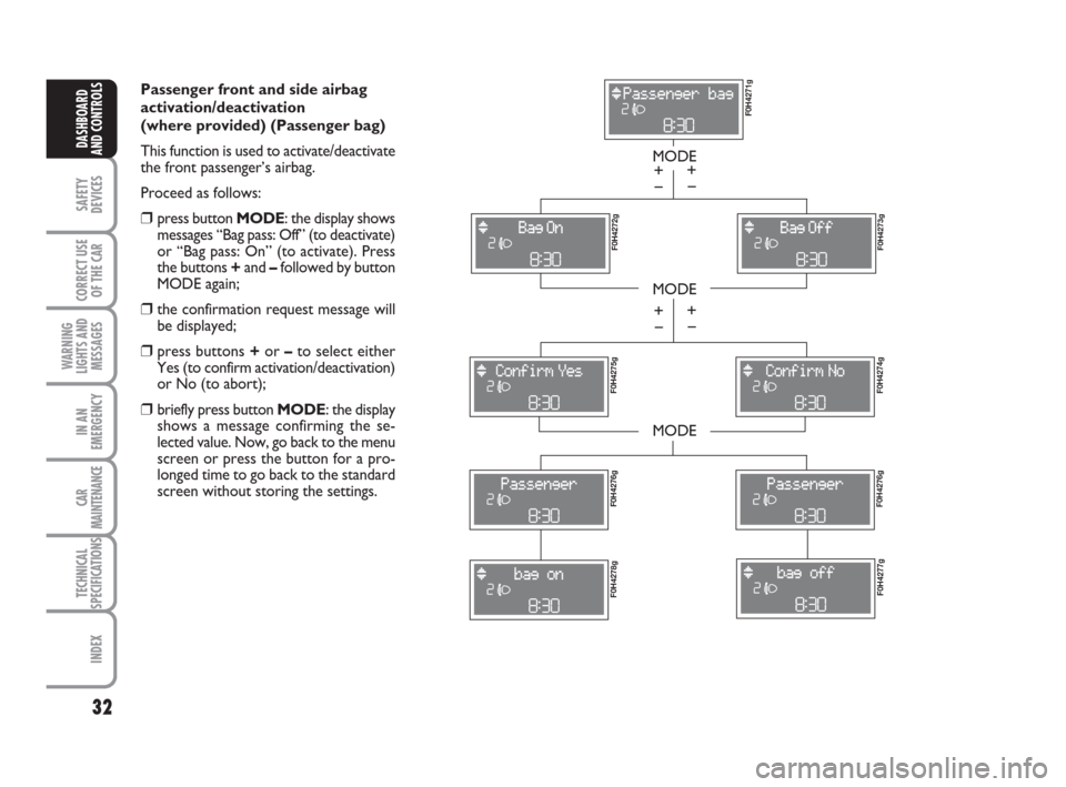
This function is used to activate/deactivate
the front passenger’s airbag.
Proceed as follows:
❒press button MODE: the display shows
messages “Bag pass: Off” (to deactivate)
or “Bag pass: On” (to activate). Press
the buttons +and –followed by button
MODE again;
❒the confirmation request message will
be displayed;
❒press buttons +or –to select either
Yes (to confirm activation/deactivation)
or No (to abort);
❒briefly press button MODE: the display
shows a message confirming the se-
lected value. Now, go back to the menu
screen or press the button for a pro-
longed time to go back to the standard
screen without storing the settings.
MODE
MODE
MODE
– +
F0H4271g F0H4272g
F0H4273g F0H4275g
F0H4274g F0H4276gF0H4276g
F0H4278gF0H4277g
– +
– +
– +
001-035 idea GB 1 ed 10-07-2008 8:27 Pagina 32
Page 34 of 210
33
SAFETY
DEVICES
CORRECT USE
OF THE CAR
WARNING
LIGHTS AND
MESSAGES
IN AN
EMERGENCY
CAR
MAINTENANCE
TECHNICAL
SPECIFICATIONS
INDEX
DASHBOARD
AND CONTROLS
Exiting the Menu
This is the last function that closes the set-
ting cycle listed in the initial menu screen.
Briefly press button MODEto go back to
the standard screen without storing the
settings.
Press button +to return to the first menu
option (Speed Beep).Both functions can be reset (to start a new
trip).
The “General Trip” function is used to dis-
play information relating to:
– Range
– Trip distance
– Average consumption
– Instant consumption
– Average speed
– Travel time (driving time).
The “Trip B” function is used to display in-
formation relating to:
– Trip distance B
– Average consumption B
– Average speed B
– Travel time B (driving time).
Note “Trip B” functions may be disabled
(see “Trip B on”). “Range” and “Instan-
taneous consumption” cannot be reset. TRIP COMPUTER
(where provided)
General features
The “Trip computer” is used to display in-
formation on car operation when the key
is turned to MAR. This function includes
a “General trip” system that monitors the
“entire mission” (trip) of the car and the
“Trip B” system that monitors the partial
mission of the car. The former function
is part of the entire mission (as illustrat-
ed in fig. 34).
001-035 idea GB 1 ed 10-07-2008 8:27 Pagina 33
Page 35 of 210
34
SAFETY
DEVICES
CORRECT USE
OF THE CAR
WARNING
LIGHTS AND
MESSAGES
IN AN
EMERGENCY
CAR
MAINTENANCE
TECHNICAL
SPECIFICATIONS
INDEX
DASHBOARD
AND CONTROLS
New mission
The new mission begins after:
– “manual” resetting by the user, by press-
ing the relevant button;
– “automatic” resetting, when the “Trip
distance” reaches 9999.9 km or when the
“Travel time” reaches 99.59 (99 hours and
59 minutes);
– disconnection/reconnection of the bat-
tery.
IMPORTANT The reset operations per-
formed after the “General Trip” message
appears are used to also reset the “Trip
B”, which, on its turn, is used to reset the
values of the corresponding function. Travel time
This value shows the time elapsed since
the start of a new mission.
IMPORTANT If information is not avail-
able, the message “----” will appear instead
of the Trip Computer values. Displaying
of the values will be resumed regularly
when normal operation is restored with-
out resetting the values displayed before
the failure nor starting a new mission.
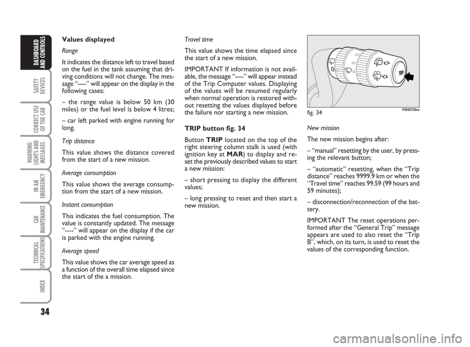
TRIP button fig. 34
Button TRIPlocated on the top of the
right steering column stalk is used (with
ignition key at MAR) to display and re-
set the previously described values to start
a new mission:
– short pressing to display the different
values;
– long pressing to reset and then start a
new mission. Values displayed
Range
It indicates the distance left to travel based
on the fuel in the tank assuming that dri-
ving conditions will not change. The mes-
sage “----” will appear on the display in the
following cases:
– the range value is below 50 km (30
miles) or the fuel level is below 4 litres;
– car left parked with engine running for
long.
Trip distance
This value shows the distance covered
from the start of a new mission.
Average consumption
This value shows the average consump-
tion from the start of a new mission.
Instant consumption
This indicates the fuel consumption. The
value is constantly updated. The message
“----” will appear on the display if the car
is parked with the engine running.
Average speed
This value shows the car average speed as
a function of the overall time elapsed since
the start of the a mission.
fig. 34F0H0755m
001-035 idea GB 1 ed 10-07-2008 8:27 Pagina 34
Page 36 of 210
35
SAFETY
DEVICES
CORRECT USE
OF THE CAR
WARNING
LIGHTS AND
MESSAGES
IN AN
EMERGENCY
CAR
MAINTENANCE
TECHNICAL
SPECIFICATIONS
INDEX
DASHBOARD
AND CONTROLS
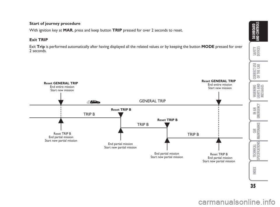
Start of journey procedure
With ignition key at MAR, press and keep button TRIPpressed for over 2 seconds to reset.
Exit TRIP
Exit Tripis performed automatically after having displayed all the related values or by keeping the button MODEpressed for over
2 seconds.
Reset TRIP B
End partial mission
Start new partial mission
End partial mission
Start new partial mission
Reset TRIP B
End partial mission
Start new partial mission Reset GENERAL TRIP
End entire mission
Start new missionReset GENERAL TRIP
End entire mission
Start new mission
End partial mission
Start new partial mission Reset TRIP B
Reset TRIP B
TRIP B
TRIP B
TRIP B GENERAL TRIP
˙
˙
˙
˙
˙
˙˙
˙
001-035 idea GB 1 ed 10-07-2008 8:27 Pagina 35
Page 52 of 210
51
SAFETY
DEVICES
CORRECT USE
OF THE CAR
WARNING
LIGHTS AND
MESSAGES
IN AN
EMERGENCY
CAR
MAINTENANCE
TECHNICAL
SPECIFICATIONS
INDEX
DASHBOARD
AND CONTROLS
AUTOMATIC
TWO-ZONE CLIMATE
CONTROL SYSTEM
(where provided)
GENERAL
The car is fitted with a two-zone climate
control system which makes it possible to
separately adjust the air temperature on
the driver’s side and on the passenger’s
side. Temperature control is based on the
“equivalent temperature” logic, i.e.: the
system continuously works to keep con-
stant the comfort inside the passenger
compartment and to compensate any vari-
ation of the outside climate conditions, in-
cluding sunshine detected by a proper sen-
sor provided for the purpose.
The climate control system automatically
controls and adjusts the following para-
meters and functions:
❒air temperature at driver/front pas-
senger vents;
❒air distribution at driver/front passen-
ger vents;
❒fan speed (continuous air flow varia-
tion);
❒compressor switching on (to cool/de-
humidify air);
❒air recirculation.
All the above functions can be changed
manually at any time, i.e.: you can always
modify one or more function settings. In
this event, the system will no longer im-
plement the automatic control of the func-
tions changed manually (except for safety
reasons, e.g.: risk of window misting).
Manual selections prevail over automatic
ones and remain in storage until the user
decides to resume automatic control, ex-
cept when the system cuts in for particu-
lar safety conditions.
The control of functions not changed man-
ually remains automatic.
The amount of air admitted to the pas-
senger compartment does not depend on
the car speed, since it is electronically con-
trolled by the fan.
In any case, the temperature of the air ad-
mitted to the passenger compartment is
controlled automatically (except when the
system is off) according to the tempera-
tures set on the driver’s and front pas-
senger’s displays or under certain climat-
ic conditions if the compressor is off).The system enables to set or to change
the following parameters and functions
manually:❒air temperatures on driver/front pas-
senger side;
❒fan speed (continuous variation);
❒air distribution on five levels (driver/
front passenger side);
❒climate control compressor on/off en-
able;
❒monozone/two-zone distribution pri-
ority;
❒fast demisting/defrosting;
❒air recirculation;
❒rear heated window;
❒system off;
036-092 idea GB 1 ed 10-07-2008 16:12 Pagina 51
Page 53 of 210
52
SAFETY
DEVICES
CORRECT USE
OF THE CAR
WARNING
LIGHTS AND
MESSAGES
IN AN
EMERGENCY
CAR
MAINTENANCE
TECHNICAL
SPECIFICATIONS
INDEX
DASHBOARD
AND CONTROLS
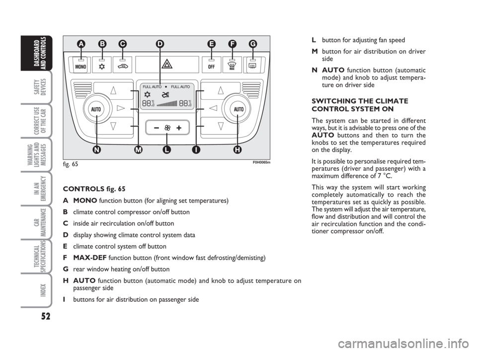
CONTROLS fig. 65
A MONOfunction button (for aligning set temperatures)
Bclimate control compressor on/off button
Cinside air recirculation on/off button
Ddisplay showing climate control system data
Eclimate control system off button
F MAX-DEFfunction button (front window fast defrosting/demisting)
Grear window heating on/off button
H AUTOfunction button (automatic mode) and knob to adjust temperature on
passenger side
Ibuttons for air distribution on passenger side
F0H0065m
Lbutton for adjusting fan speed
Mbutton for air distribution on driver
side
N AUTOfunction button (automatic
mode) and knob to adjust tempera-
ture on driver side
SWITCHING THE CLIMATE
CONTROL SYSTEM ON
The system can be started in different
ways, but it is advisable to press one of the
AUTObuttons and then to turn the
knobs to set the temperatures required
on the display.
It is possible to personalise required tem-
peratures (driver and passenger) with a
maximum difference of 7 °C.
This way the system will start working
completely automatically to reach the
temperatures set as quickly as possible.
The system will adjust the air temperature,
flow and distribution and will control the
air recirculation function and the condi-
tioner compressor on/off.
fig. 65
036-092 idea GB 1 ed 10-07-2008 16:12 Pagina 52