stop start FIAT IDEA 2009 1.G User Guide
[x] Cancel search | Manufacturer: FIAT, Model Year: 2009, Model line: IDEA, Model: FIAT IDEA 2009 1.GPages: 210, PDF Size: 3.62 MB
Page 58 of 210
57
SAFETY
STARTING
AND DRIVING
WARNING
LIGHTS AND
MESSAGES
IN AN
EMERGENCY
MAINTENANCE
AND CARE
TECHNICAL
SPECIFICATIONS
ALPHABETICAL
INDEX
DASHBOARD
AND CONTROLS
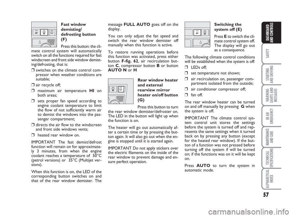
Fast window
demisting/
defrosting button
(F)
Press this button: the cli-
mate control system will automatically
switch on all the functions required for fast
windscreen and front side window demist-
ing/defrosting, that is:
❒switches on the climate control com-
pressor when weather conditions are
suitable;
❒air recycle off;
❒maximum air temperature HIon
both areas;
❒sets proper fan speed according to
engine coolant temperature to limit
the flow of not sufficiently warm air
to demist the windows into the pas-
senger compartment;
❒directs the air flow to the windscreen
and front side windows vents;
❒heated rear window on.
IMPORTANT The fast demist/defrost
function will remain on for approximate-
ly 3 minutes, from when the engine
coolant reaches a temperature of 50°C
(petrol versions) or 35°C (Multijet ver-
sions).
When this function is on, the LED of the
corresponding button switches on and
that of the rear window demister. Themessage FULL AUTOgoes off on the
display.
You can only adjust the fan speed and
switch the rear window demister off
manually when this function is active.
To restore running operations before
this function was activated, press either
button F-fig. 62, air recirculation but-
ton C, compressor button Bor button
AUTO Nor H
Rear window heater
and external
rearview mirror
heater on/off button
(G)
Press this button to turn
the rear window demister/defroster on.
The LED in the button will light up when
the function is on.
The heater will go out automatically af-
ter a certain time or by pressing the but-
ton again. It will also go out when the en-
gine is stopped until it is started again.
IMPORTANT Do not apply stickers over
the electric filaments on the inside of the
rear window to prevent damage and en-
sure perfect operation.Switching the
system off (E)
Press Eto switch the cli-
mate control system off.
The display will go out
as a consequence.
The following climate control conditions
will be established when the system is off:
❒LEDs off;
❒set temperature not shown;
❒air recirculation on, passenger com-
partment isolated from the outside;
❒air conditioner compressor off;
❒fan off.
The rear window heater can be turned
on and off manually by pressing Gwhen
the system is off.
IMPORTANT The climate control sys-
tem control unit stores the settings
before the system is turned off and rep-
resents the same settings when it turned
back on by pressing any button (except
for the heated rear window). If the but-
ton of a function was not pressed before
turning off the system if will be turned
on; if the functions was on it will be kept
on.
Press AUTOto turn the system in
automatic mode.
Page 59 of 210
58
SAFETY
STARTING
AND DRIVING
WARNING
LIGHTS AND
MESSAGES
IN AN
EMERGENCY
MAINTENANCE
AND CARE
TECHNICAL
SPECIFICATIONS
ALPHABETICAL
INDEX
DASHBOARD
AND CONTROLS
EXTERNAL LIGHTS
The left-hand lever includes the controls
for the external lights.
The external lights can only be switched
on when the ignition key is at MAR.
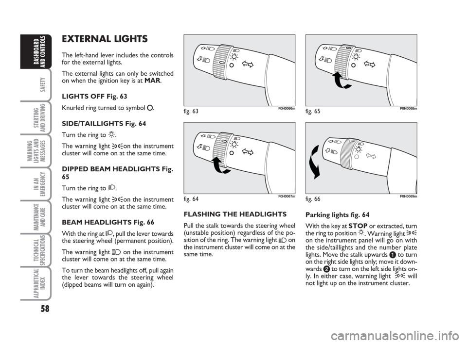
LIGHTS OFF Fig. 63
Knurled ring turned to symbol
å.
SIDE/TAILLIGHTS Fig. 64
Turn the ring to
6.
The warning light
3on the instrument
cluster will come on at the same time.
DIPPED BEAM HEADLIGHTS Fig.
65
Turn the ring to 2.
The warning light
3on the instrument
cluster will come on at the same time.
BEAM HEADLIGHTS Fig. 66
With the ring at 2, pull the lever towards
the steering wheel (permanent position).
The warning light
1on the instrument
cluster will come on at the same time.
To turn the beam headlights off, pull again
the lever towards the steering wheel
(dipped beams will turn on again).FLASHING THE HEADLIGHTS
Pull the stalk towards the steering wheel
(unstable position) regardless of the po-
sition of the ring. The warning light
1on
the instrument cluster will come on at the
same time.Parking lights fig. 64
With the key at STOPor extracted, turn
the ring to position 6. Warning light 3on the instrument panel will go on with
the side/taillights and the number plate
lights. Move the stalk upwards ato turn
on the right side lights only; move it down-
wards bto turn on the left side lights on-
ly. In either case, warning light
3will
not light up on the instrument cluster.
fig. 63F0H0066m
fig. 66F0H0069m
fig. 65F0H0068m
fig. 64F0H0067m
Page 60 of 210
59
SAFETY
STARTING
AND DRIVING
WARNING
LIGHTS AND
MESSAGES
IN AN
EMERGENCY
MAINTENANCE
AND CARE
TECHNICAL
SPECIFICATIONS
ALPHABETICAL
INDEX
DASHBOARD
AND CONTROLS
fig. 67F0H0071mfig. 68F0H0070mfig. 69F0H0072m
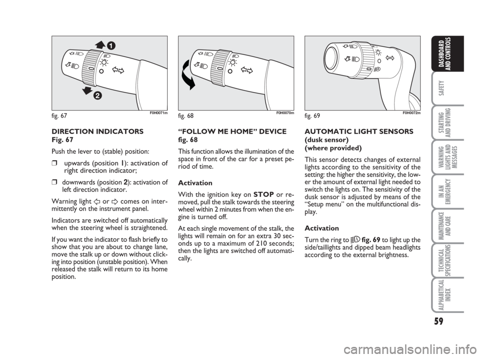
DIRECTION INDICATORS
Fig. 67
Push the lever to (stable) position:
❒upwards (position 11): activation of
right direction indicator;
❒
downwards (position 2): activation of
left direction indicator.
Warning light
ForDcomes on inter-
mittently on the instrument panel.
Indicators are switched off automatically
when the steering wheel is straightened.
If you want the indicator to flash briefly to
show that you are about to change lane,
move the stalk up or down without click-
ing into position (unstable position). When
released the stalk will return to its home
position.“FOLLOW ME HOME” DEVICE
fig. 68
This function allows the illumination of the
space in front of the car for a preset pe-
riod of time.
Activation
With the ignition key on STOPor re-
moved, pull the stalk towards the steering
wheel within 2 minutes from when the en-
gine is turned off.
At each single movement of the stalk, the
lights will remain on for an extra 30 sec-
onds up to a maximum of 210 seconds;
then the lights are switched off automati-
cally. AUTOMATIC LIGHT SENSORS
(dusk sensor)
(where provided)
This sensor detects changes of external
lights according to the sensitivity of the
setting: the higher the sensitivity, the low-
er the amount of external light needed to
switch the lights on. The sensitivity of the
dusk sensor is adjusted by means of the
“Setup menu” on the multifunctional dis-
play.
Activation
Turn the ring to
2Afig. 69to light up the
side/taillights and dipped beam headlights
according to the external brightness.
Page 62 of 210
61
SAFETY
STARTING
AND DRIVING
WARNING
LIGHTS AND
MESSAGES
IN AN
EMERGENCY
MAINTENANCE
AND CARE
TECHNICAL
SPECIFICATIONS
ALPHABETICAL
INDEX
DASHBOARD
AND CONTROLS
Operation in position Eis limited to the
time during which the lever is kept in that
position manually. When released, the
stalk will return to position Aand the
wiper will be automatically stopped.
IMPORTANT Replace wiper blades as
specified in the “Maintenance and care”
chapter. RAIN SENSOR
(where provided)
The rain sensor is located behind the dri-
ving mirror in contact with the windscreen
and has the purpose of automatically ad-
justing the frequency of the windscreen
wiper strokes as to the rain intensity.
IMPORTANT Keep clean the glass in the
sensor area.
Activation
Move the right stalk down by one click.
The activation of the rain sensor is sig-
nalled by a control acquisition flick.
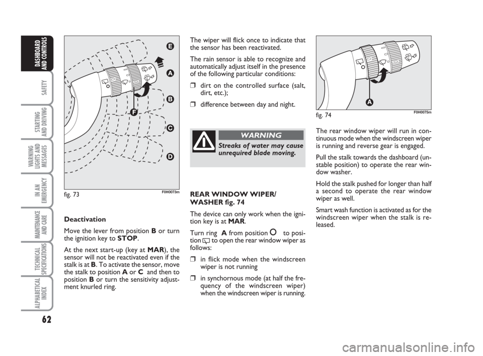
Turn the ring F-fig. 73to increase the rain
sensor sensitivity.
The increase of the sensitivity of the rain
sensor is signalled by a control and acqui-
sition flick.
The smart cycle is started when the wind-
screen wiper is turned on while the rain
sensor is active without supplementary
flick after 5 seconds. The sensor will re-
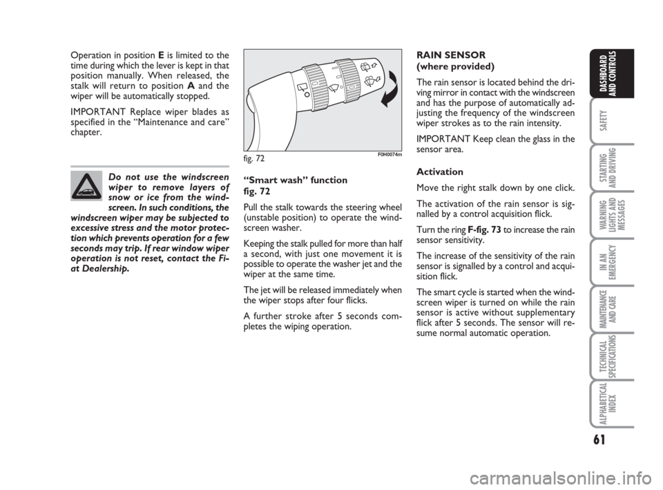
sume normal automatic operation. “Smart wash” function
fig. 72
Pull the stalk towards the steering wheel
(unstable position) to operate the wind-
screen washer.
Keeping the stalk pulled for more than half
a second, with just one movement it is
possible to operate the washer jet and the
wiper at the same time.
The jet will be released immediately when
the wiper stops after four flicks.
A further stroke after 5 seconds com-
pletes the wiping operation. Do not use the windscreen
wiper to remove layers of
snow or ice from the wind-
screen. In such conditions, the
windscreen wiper may be subjected to
excessive stress and the motor protec-
tion which prevents operation for a few
seconds may trip. If rear window wiper
operation is not reset, contact the Fi-
at Dealership.
fig. 72F0H0074m
Page 63 of 210
62
SAFETY
STARTING
AND DRIVING
WARNING
LIGHTS AND
MESSAGES
IN AN
EMERGENCY
MAINTENANCE
AND CARE
TECHNICAL
SPECIFICATIONS
ALPHABETICAL
INDEX
DASHBOARD
AND CONTROLS
The wiper will flick once to indicate that
the sensor has been reactivated.
The rain sensor is able to recognize and
automatically adjust itself in the presence
of the following particular conditions:
❒dirt on the controlled surface (salt,
dirt, etc.);
❒difference between day and night.
Deactivation
Move the lever from position Bor turn
the ignition key to STOP.
At the next start-up (key at MAR), the
sensor will not be reactivated even if the
stalk is at B. To activate the sensor, move
the stalk to position Aor C and then to
position Bor turn the sensitivity adjust-
ment knurled ring.
fig. 73F0H0073m
Streaks of water may cause
unrequired blade moving.
WARNINGThe rear window wiper will run in con-
tinuous mode when the windscreen wiper
is running and reverse gear is engaged.
Pull the stalk towards the dashboard (un-
stable position) to operate the rear win-
dow washer.
Hold the stalk pushed for longer than half
a second to operate the rear window
wiper as well.
Smart wash function is activated as for the
windscreen wiper when the stalk is re-
leased.
fig. 74F0H0075m
REAR WINDOW WIPER/
WASHER fig. 74
The device can only work when the igni-
tion key is at MAR.
Turn ring Afrom position
åto posi-
tion
'to open the rear window wiper as
follows:
❒in flick mode when the windscreen
wiper is not running
❒in synchornous mode (at half the fre-
quency of the windscreen wiper)
when the windscreen wiper is running.
Page 65 of 210
64
SAFETY
STARTING
AND DRIVING
WARNING
LIGHTS AND
MESSAGES
IN AN
EMERGENCY
MAINTENANCE
AND CARE
TECHNICAL
SPECIFICATIONS
ALPHABETICAL
INDEX
DASHBOARD
AND CONTROLS
REDUCING THE MEMORIZED
SPEED
The stored speed can be increased in two
ways:
❒by turning the device off and then
storing a new speed;
or
❒ moving the stalk downwards (–) until
reaching the new speed which will be
memorised automatically.
Each movement of the lever will corre-
spond to a slight reduction in speed (about
1 km/h), while keeping the lever held
downwards will correspond to a continu-
ous speed reduction.
DISENGAGING THE DEVICE
Turn ring A-fig. 75to OFFor the igni-
tion key to STOP. If the device has been
disengaged, for example by pressing the
brake or clutch pedal.
If the device is faulty, turn
ring A to OFF, check the fuse
and contact a Fiat Dealership.
WARNING
COURTESY LIGHTS
FRONT CEILING LIGHT fig. 76
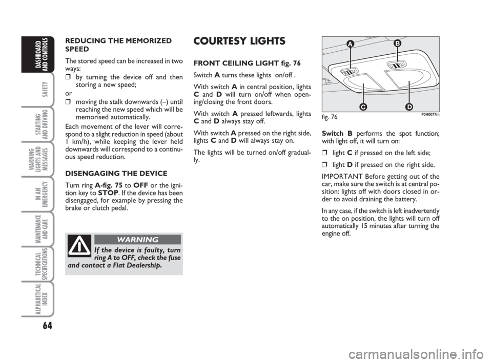
Switch Aturns these lights on/off .
With switch Ain central position, lights
Cand Dwill turn on/off when open-
ing/closing the front doors.
With switch Apressed leftwards, lights
Cand Dalways stay off.
With switch Apressed on the right side,
lights C andD will always stay on.
The lights will be turned on/off gradual-
ly.Switch Bperforms the spot function;
with light off, it will turn on:
❒ light Cif pressed on the left side;
❒light Dif pressed on the right side.
IMPORTANT Before getting out of the
car, make sure the switch is at central po-
sition: lights off with doors closed in or-
der to avoid draining the battery.
In any case, if the switch is left inadvertently
to the on position, the lights will turn off
automatically 15 minutes after turning the
engine off.
fig. 76F0H0077m
Page 66 of 210
65
SAFETY
STARTING
AND DRIVING
WARNING
LIGHTS AND
MESSAGES
IN AN
EMERGENCY
MAINTENANCE
AND CARE
TECHNICAL
SPECIFICATIONS
ALPHABETICAL
INDEX
DASHBOARD
AND CONTROLS
fig. 77F0H0078mfig. 78F0H0079m
fig. 79F0H0254m
REAR CEILING LIGHT
(where provided)
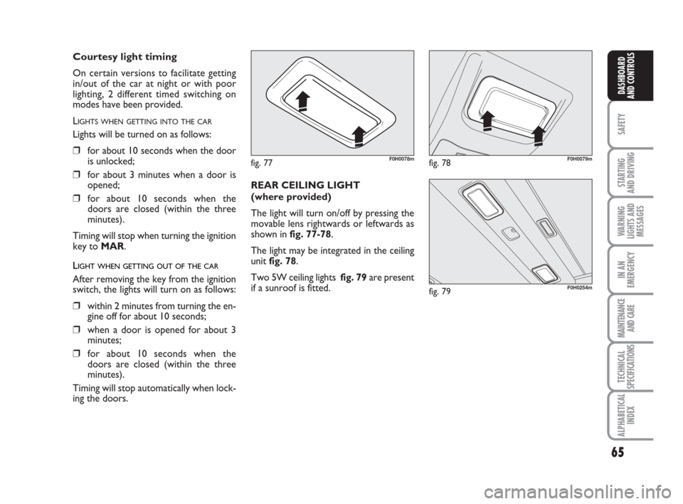
The light will turn on/off by pressing the
movable lens rightwards or leftwards as
shown in fig. 77-78.
The light may be integrated in the ceiling
unit fig. 78.
Two 5W ceiling lights fig. 79are present
if a sunroof is fitted.
Courtesy light timing
On certain versions to facilitate getting
in/out of the car at night or with poor
lighting, 2 different timed switching on
modes have been provided.
L
IGHTS WHEN GETTING INTO THE CAR
Lights will be turned on as follows:
❒for about 10 seconds when the door
is unlocked;
❒for about 3 minutes when a door is
opened;
❒for about 10 seconds when the
doors are closed (within the three
minutes).
Timing will stop when turning the ignition
key to MAR.
LIGHT WHEN GETTING OUT OF THE CAR
After removing the key from the ignition
switch, the lights will turn on as follows:
❒within 2 minutes from turning the en-
gine off for about 10 seconds;
❒when a door is opened for about 3
minutes;
❒for about 10 seconds when the
doors are closed (within the three
minutes).
Timing will stop automatically when lock-
ing the doors.
Page 68 of 210
67
SAFETY
STARTING
AND DRIVING
WARNING
LIGHTS AND
MESSAGES
IN AN
EMERGENCY
MAINTENANCE
AND CARE
TECHNICAL
SPECIFICATIONS
ALPHABETICAL
INDEX
DASHBOARD
AND CONTROLS
FUEL CUT OFF SWITCH
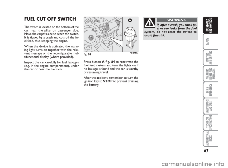
The switch is located on the bottom of the
car, near the pillar on passenger side.
Move the carpet aside to reach the switch.
It is tipped by a crash and cuts off the fu-
el feed, thus stopping the engine.
When the device is activated the warn-
ing light turns on together with the rele-
vant message on the reconfigurable mul-
tifunctional display (where provided).
Inspect the car carefully for fuel leakages
(e.g. in the engine compartment), under
the car or near the fuel tank. Press button A-fig. 84to reactivate the
fuel feed system and turn the lights on if
no leakage is found and the car is worthy
of resuming travel.
After the accident, remember to turn the
ignition key to STOPto prevent draining
the battery.
fig. 84F0H0741m
If, after a crash, you smell fu-
el or see leaks from the fuel
system, do not reset the switch to
avoid fine risk.
WARNING
Page 73 of 210
72
SAFETY
STARTING
AND DRIVING
WARNING
LIGHTS AND
MESSAGES
IN AN
EMERGENCY
MAINTENANCE
AND CARE
TECHNICAL
SPECIFICATIONS
ALPHABETICAL
INDEX
DASHBOARD
AND CONTROLS
SUNROOF
(where provided)
The sun roof has an anti-pinch safety sys-
tem capable of detecting the presence of
an object whilst the roof is closing; when
this happens the system stops and the
glass travel is immediately reversed.
The large “Skydome” sunroof consists of
two glass panels, one fixed and one mo-
bile, with sun curtains which can be
opened and closed manually.
The sun roof can only be operated with
the ignition key in the MAR position. The
button near the front ceiling lights is used
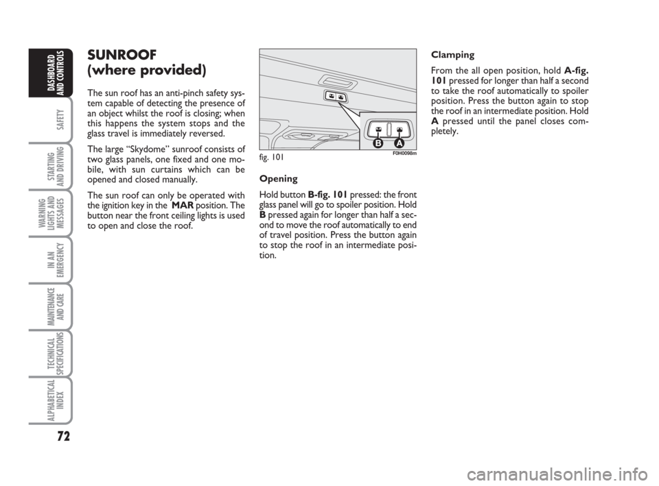
to open and close the roof. Clamping
From the all open position, hold A-fig.
101pressed for longer than half a second
to take the roof automatically to spoiler
position. Press the button again to stop
the roof in an intermediate position. Hold
Apressed until the panel closes com-
pletely.
fig. 101F0H0098m
Opening
Hold button B-fig. 101pressed: the front
glass panel will go to spoiler position. Hold
Bpressed again for longer than half a sec-
ond to move the roof automatically to end
of travel position. Press the button again
to stop the roof in an intermediate posi-
tion.
Page 75 of 210
74
SAFETY
STARTING
AND DRIVING
WARNING
LIGHTS AND
MESSAGES
IN AN
EMERGENCY
MAINTENANCE
AND CARE
TECHNICAL
SPECIFICATIONS
ALPHABETICAL
INDEX
DASHBOARD
AND CONTROLS
ELECTRIC WINDOWS
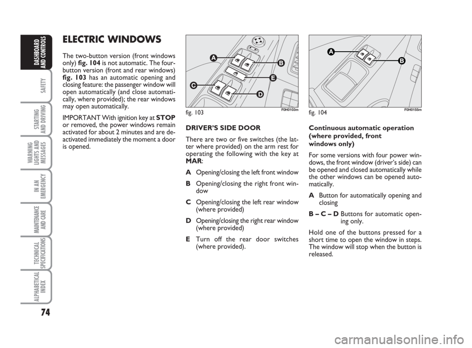
The two-button version (front windows
only) fig. 104 is not automatic. The four-
button version (front and rear windows)
fig. 103 has an automatic opening and
closing feature: the passenger window will
open automatically (and close automati-
cally, where provided); the rear windows
may open automatically.
IMPORTANT With ignition key at STOP
or removed, the power windows remain
activated for about 2 minutes and are de-
activated immediately the moment a door
is opened.
fig. 103F0H0103mfig. 104F0H0155m
DRIVER’S SIDE DOOR
There are two or five switches (the lat-
ter where provided) on the arm rest for
operating the following with the key at
MAR:
AOpening/closing the left front window
BOpening/closing the right front win-
dow
COpening/closing the left rear window
(where provided)
DOpening/closing the right rear window
(where provided)
ETurn off the rear door switches
(where provided).Continuous automatic operation
(where provided, front
windows only)
For some versions with four power win-
dows, the front window (driver’s side) can
be opened and closed automatically while
the other windows can be opened auto-
matically.
AButton for automatically opening and
closing
B – C – DButtons for automatic open-
ing only.
Hold one of the buttons pressed for a
short time to open the window in steps.
The window will stop when the button is
released.