lock FIAT IDEA 2012 1.G Owner's Manual
[x] Cancel search | Manufacturer: FIAT, Model Year: 2012, Model line: IDEA, Model: FIAT IDEA 2012 1.GPages: 210, PDF Size: 3.65 MB
Page 42 of 210
41
SAFETY
DEVICES
CORRECT USE
OF THE CAR
WARNING
LIGHTS AND
MESSAGES
IN AN
EMERGENCY
CAR
MAINTENANCE
TECHNICAL
SPECIFICATIONS
INDEX
DASHBOARD
AND CONTROLS
HEAD RESTRAINTS
FRONT SEATS
Head restraints are adjustable in height.
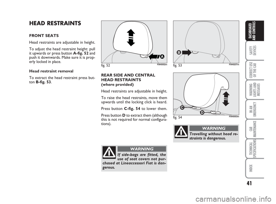
To adjust the head restraint height: pull
it upwards or press button A-fig. 52and
push it downwards. Make sure it is prop-
erly locked in place.
Head restraint removal
To extract the head restraint press but-
ton B-fig. 53.
fig. 52F0H0052mfig. 53F0H0237m
fig. 54F0H0053m
REAR SIDE AND CENTRAL
HEAD RESTRAINTS
(where provided)
Head restraints are adjustable in height.
To raise the head restraints, move them
upwards until the locking click is heard.
Press button C-fig. 54to lower them.
Press button Dto extract them (although
this is not required for normal configura-
tions).
If side-bags are fitted, the
use of seat covers not pur-
chased at Lineaccessori Fiat is dan-
gerous.
WARNING
Travelling without head re-
straints is dangerous.
WARNING
036-092 idea GB 1 ed 10-07-2008 16:12 Pagina 41
Page 43 of 210
42
SAFETY
DEVICES
CORRECT USE
OF THE CAR
WARNING
LIGHTS AND
MESSAGES
IN AN
EMERGENCY
CAR
MAINTENANCE
TECHNICAL
SPECIFICATIONS
INDEX
DASHBOARD
AND CONTROLS
Remember that the head re-
straints should be adjusted
to support the back of your head and
not your neck. Only in this position
do they exert their protective action.
WARNING
To optimise head restraint
protective action, adjust the
seat back upright and keep your head
as close as possible to the head re-
straint.
WARNING
When refitting the head re-
straint, check for proper po-
sitioning and locking.
WARNING
Saddle-shaped rear head re-
straints optimise visibility
and shall always be set in the position
of use by rear passengers.
WARNING
REARVIEW MIRRORS
DRIVING MIRROR
The mirror is fitted with a safety device
that causes it to be released in the event
of a violent crash.
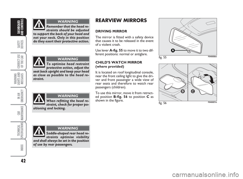
Use lever A-fig. 55to move it to two dif-
ferent positions: normal or antiglare.
CHILD’S WATCH MIRROR
(where provided)
It is located on roof longitudinal console,
near the front ceiling light to give the dri-
ver and front passenger a wide view of
rear seats and therefore to watch rear
passengers (children).
To use this mirror, move it from retract-
ed position B-fig. 56to position Cas
shown in the figure.
fig. 55F0H0056m
fig. 56F0H0057m
036-092 idea GB 1 ed 10-07-2008 16:12 Pagina 42
Page 47 of 210
46
SAFETY
DEVICES
CORRECT USE
OF THE CAR
WARNING
LIGHTS AND
MESSAGES
IN AN
EMERGENCY
CAR
MAINTENANCE
TECHNICAL
SPECIFICATIONS
INDEX
DASHBOARD
AND CONTROLS
AIR DISTRIBUTION
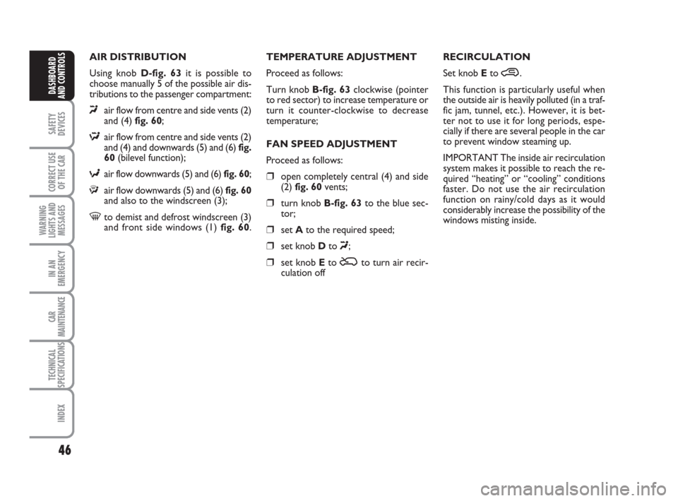
Using knob D-fig. 63it is possible to
choose manually 5 of the possible air dis-
tributions to the passenger compartment:
«air flow from centre and side vents (2)
and (4) fig. 60;
Δair flow from centre and side vents (2)
and (4) and downwards (5) and (6) fig.
60(bilevel function);
≈air flow downwards (5) and (6) fig. 60;
ƒair flow downwards (5) and (6) fig. 60
and also to the windscreen (3);
-to demist and defrost windscreen (3)
and front side windows (1) fig. 60.TEMPERATURE ADJUSTMENT
Proceed as follows:
Turn knob B-fig. 63clockwise (pointer
to red sector) to increase temperature or
turn it counter-clockwise to decrease
temperature;
FAN SPEED ADJUSTMENT
Proceed as follows:
❒open completely central (4) and side
(2) fig. 60vents;
❒turn knob B-fig. 63to the blue sec-
tor;
❒set Ato the required speed;
❒set knob Dto «;
❒set knob Eto Úto turn air recir-
culation offRECIRCULATION
Set knob Eto ….
This function is particularly useful when
the outside air is heavily polluted (in a traf-
fic jam, tunnel, etc.). However, it is bet-
ter not to use it for long periods, espe-
cially if there are several people in the car
to prevent window steaming up.
IMPORTANT The inside air recirculation
system makes it possible to reach the re-
quired “heating” or “cooling” conditions
faster. Do not use the air recirculation
function on rainy/cold days as it would
considerably increase the possibility of the
windows misting inside.
036-092 idea GB 1 ed 10-07-2008 16:12 Pagina 46
Page 50 of 210
49
SAFETY
DEVICES
CORRECT USE
OF THE CAR
WARNING
LIGHTS AND
MESSAGES
IN AN
EMERGENCY
CAR
MAINTENANCE
TECHNICAL
SPECIFICATIONS
INDEX
DASHBOARD
AND CONTROLS
TEMPERATURE ADJUSTMENT
Proceed as follows:
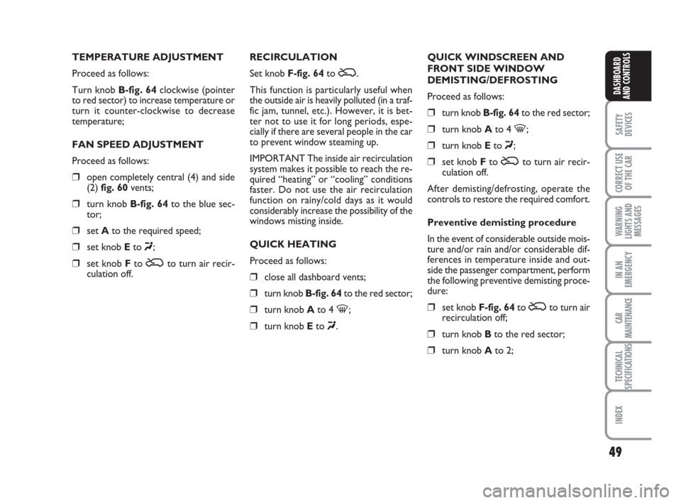
Turn knob B-fig. 64clockwise (pointer
to red sector) to increase temperature or
turn it counter-clockwise to decrease
temperature;
FAN SPEED ADJUSTMENT
Proceed as follows:
❒open completely central (4) and side
(2) fig. 60vents;
❒turn knob B-fig. 64to the blue sec-
tor;
❒set Ato the required speed;
❒set knob Eto «;
❒set knob Fto Úto turn air recir-
culation off.RECIRCULATION
Set knob F-fig. 64to Ú.
This function is particularly useful when
the outside air is heavily polluted (in a traf-
fic jam, tunnel, etc.). However, it is bet-
ter not to use it for long periods, espe-
cially if there are several people in the car
to prevent window steaming up.
IMPORTANT The inside air recirculation
system makes it possible to reach the re-
quired “heating” or “cooling” conditions
faster. Do not use the air recirculation
function on rainy/cold days as it would
considerably increase the possibility of the
windows misting inside.
QUICK HEATING
Proceed as follows:
❒close all dashboard vents;
❒turn knob B-fig. 64to the red sector;
❒turn knob Ato 4 -;
❒turn knob Eto «.QUICK WINDSCREEN AND
FRONT SIDE WINDOW
DEMISTING/DEFROSTING
Proceed as follows:
❒turn knob B-fig. 64to the red sector;
❒turn knob Ato 4 -;
❒turn knob Eto «;
❒set knob Fto Úto turn air recir-
culation off.
After demisting/defrosting, operate the
controls to restore the required comfort.
Preventive demisting procedure
In the event of considerable outside mois-
ture and/or rain and/or considerable dif-
ferences in temperature inside and out-
side the passenger compartment, perform
the following preventive demisting proce-
dure:
❒set knob F-fig. 64 to Úto turn air
recirculation off;
❒turn knob Bto the red sector;
❒turn knob Ato 2;
036-092 idea GB 1 ed 10-07-2008 16:12 Pagina 49
Page 54 of 210
53
SAFETY
DEVICES
CORRECT USE
OF THE CAR
WARNING
LIGHTS AND
MESSAGES
IN AN
EMERGENCY
CAR
MAINTENANCE
TECHNICAL
SPECIFICATIONS
INDEX
DASHBOARD
AND CONTROLS
During fully automatic operation, the on-
ly manual settings required are the fol-
lowing:
❒MONO, to align the air temperature
and distribution set on the passenger’s
side (front or rear) with that on the
driver’s side;
❒…, air recirculation, to keep it al-
ways on or off;
❒-, to speed up demisting/defrosting
of windscreen, front side windows,
rear window and door mirrors;
❒(, to demist/defrost the rear heat-
ed window and the door mirrors.
During completely automatic system op-
eration, the temperatures, air distribution
and the fan speed set can be changed at
any time through the relevant buttons or
knobs: the system will automatically
change its settings to adjust to the new re-
quirements.
During full automatic operation (FULL
AUTO), any change in air distribution
and/or air flow and/or compressor turn-
ing on and/or air recirculation will obtain
FULLdisappearing. In this way functions
will be controlled manually until pressing
the AUTObutton again. The fan speed is
the same for all passenger compartment
areas.With one or more functions engaged man-
ually, the adjustment of the temperature
of the air admitted to the passenger com-
partment continues to be controlled au-
tomatically by the system, except with the
climate control compressor off. In fact, in
this condition, the air admitted to the pas-
senger compartment cannot have a low-
er temperature than the outside air.
CONTROLS
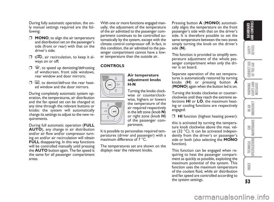
Air temperature
adjustment knobs
H-N
Turning the knobs clock-
wise or counterclock-
wise, highers or lowers
the temperature of the
air required respectively
in the left zone (knob N)
or right zone (knob H)
of the passenger com-
partment.
It is possible to personalise required tem-
peratures (driver and passenger) with a
maximum difference of 7 °C.
The temperatures set are shown on the
displays near the relevant knobs.Pressing button A(MONO) automati-
cally aligns the temperature on the front
passenger’s side with that on the driver’s
side. It is therefore possible to set the
same temperature between the two zones
simply turning the knob on the driver’s
side (N).
This function is provided to simplify tem-
perature adjustment of the whole pas-
senger compartment when only the dri-
ver is on board.
Separate operation of the set tempera-
tures is automatically restored by turning
knobs (H) or pressing button A
(MONO) again when the button led is on.
Turning the knobs clockwise or counter-
clockwise until they reach the extreme se-
lections HIor LO, the maximum heat-
ing or cooling functions are respectively
engaged:
❒HIfunction (highest heating power):
this is activated by turning the tempera-
ture knob clockwise above the max. val-
ue (32 °C). It can be activated indepen-
dently from the driver’s or passenger’s
side or both (also selecting the MONO
function).
This function can be engaged when re-
quiring to heat the passenger compart-
ment as quickly as possible, exploiting the
maximum potential of the system. This
function uses the maximum temperature
of the coolant fluid, while air distribution
and fan speed are controlled according to
the system settings.
036-092 idea GB 1 ed 10-07-2008 16:12 Pagina 53
Page 55 of 210
54
SAFETY
DEVICES
CORRECT USE
OF THE CAR
WARNING
LIGHTS AND
MESSAGES
IN AN
EMERGENCY
CAR
MAINTENANCE
TECHNICAL
SPECIFICATIONS
INDEX
DASHBOARD
AND CONTROLS
More particularly, max. fan speed will not
be immediately engaged if coolant is not
hot enough; this to prevent admitting air
that is not warm enough to the passenger
compartment.
All manual settings are however possible
with this function on.
To switch the function off, simply turn the
temperature knob counterclockwise and
set the required temperature.
❒LOfunction (highest cooling power):
this is activated by turning the tempera-
ture knob counterclockwise below the
min. value (16 °C). It can be activated in-
dependently from the driver’s or passen-
ger’s side or both (also selecting the
MONOfunction).
This function can be engaged when re-
quiring to cool the passenger compart-
ment as quickly as possible, exploiting the
maximum potential of the system. This
function engages inside air recirculation
and climate control compressor, while air
distribution and fan speed are controlled
according to environmental conditions. All manual settings are however possible
with this function on.
To switch the function off, simply turn the
temperature knob clockwise and set the
required temperature.
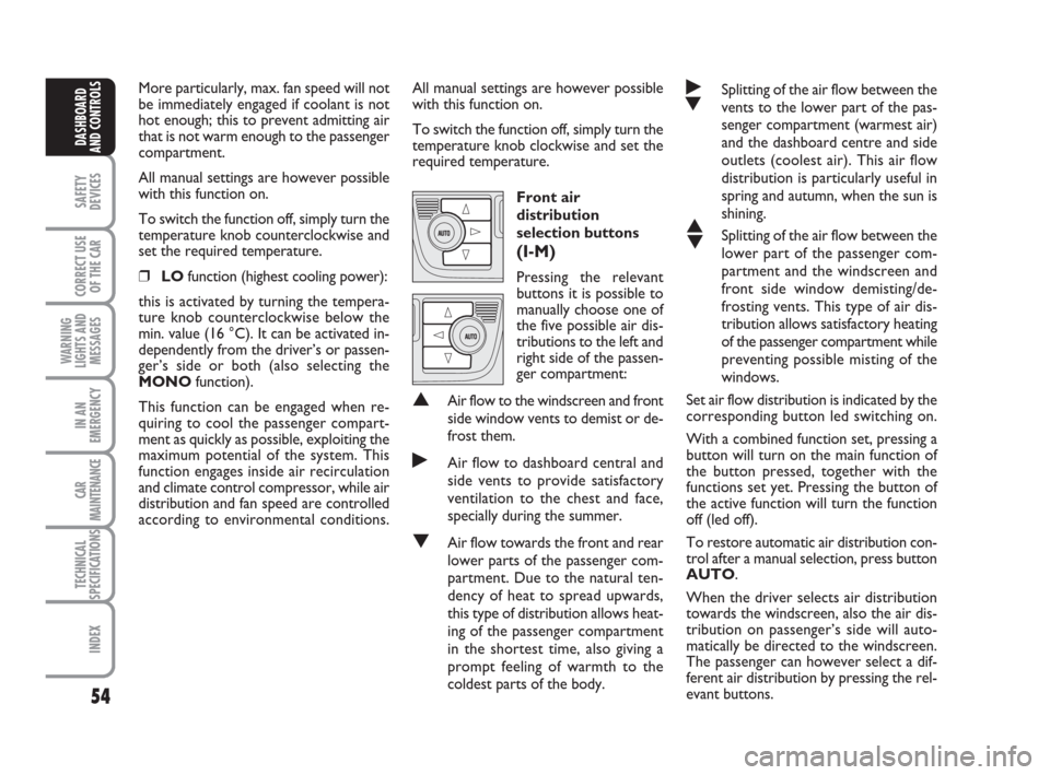
Front air
distribution
selection buttons
(I-M)
Pressing the relevant
buttons it is possible to
manually choose one of
the five possible air dis-
tributions to the left and
right side of the passen-
ger compartment:
▲Air flow to the windscreen and front
side window vents to demist or de-
frost them.
˙Air flow to dashboard central and
side vents to provide satisfactory
ventilation to the chest and face,
specially during the summer.
▼Air flow towards the front and rear
lower parts of the passenger com-
partment. Due to the natural ten-
dency of heat to spread upwards,
this type of distribution allows heat-
ing of the passenger compartment
in the shortest time, also giving a
prompt feeling of warmth to the
coldest parts of the body.
˙
▼Splitting of the air flow between the
vents to the lower part of the pas-
senger compartment (warmest air)
and the dashboard centre and side
outlets (coolest air). This air flow
distribution is particularly useful in
spring and autumn, when the sun is
shining.
▲
▼Splitting of the air flow between the
lower part of the passenger com-
partment and the windscreen and
front side window demisting/de-
frosting vents. This type of air dis-
tribution allows satisfactory heating
of the passenger compartment while
preventing possible misting of the
windows.
Set air flow distribution is indicated by the
corresponding button led switching on.
With a combined function set, pressing a
button will turn on the main function of
the button pressed, together with the
functions set yet. Pressing the button of
the active function will turn the function
off (led off).
To restore automatic air distribution con-
trol after a manual selection, press button
AUTO.
When the driver selects air distribution
towards the windscreen, also the air dis-
tribution on passenger’s side will auto-
matically be directed to the windscreen.
The passenger can however select a dif-
ferent air distribution by pressing the rel-
evant buttons.
036-092 idea GB 1 ed 10-07-2008 16:12 Pagina 54
Page 66 of 210
65
SAFETY
DEVICES
CORRECT USE
OF THE CAR
WARNING
LIGHTS AND
MESSAGES
IN AN
EMERGENCY
CAR
MAINTENANCE
TECHNICAL
SPECIFICATIONS
INDEX
DASHBOARD
AND CONTROLS
Ceiling light timing
Two timing strategies are available in or-
der to facilitate getting in and out of the
car, especially at night in dark areas:
T
IMING FOR GETTING INTO THE CAR
The ceiling lights will come on as follows:
❒for about 10 seconds when a door is
unlocked;
❒for about 3 minutes when a door is
opened;
❒for about 10 seconds when a door is
closed (within the 3 minutes).
Timing will be stopped when the ignition
key is turned to MAR.
T
IMING FOR GETTING OUT OF THE CAR
The ceiling lights will come on as follows
when the key is removed from the igni-
tion switch:
❒for about 10 seconds within 2 min-
utes after stopping the engine;
❒for about 3 minutes when a door is
opened;
❒for about 10 seconds when a door is
closed (within the three minutes).
The timeout will automatically end when
the doors are locked.
fig. 80F0H0078mfig. 81F0H0079m
fig. 82F0H0254m
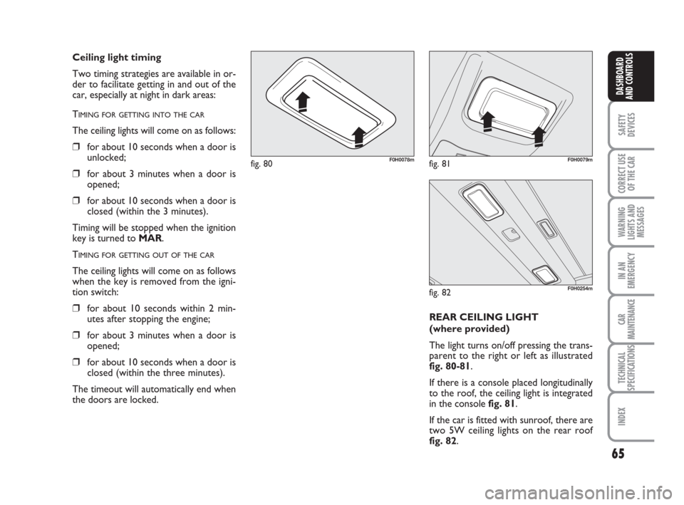
REAR CEILING LIGHT
(where provided)
The light turns on/off pressing the trans-
parent to the right or left as illustrated
fig. 80-81.
If there is a console placed longitudinally
to the roof, the ceiling light is integrated
in the console fig. 81.
If the car is fitted with sunroof, there are
two 5W ceiling lights on the rear roof
fig. 82.
036-092 idea GB 1 ed 10-07-2008 16:12 Pagina 65
Page 74 of 210
73
SAFETY
DEVICES
CORRECT USE
OF THE CAR
WARNING
LIGHTS AND
MESSAGES
IN AN
EMERGENCY
CAR
MAINTENANCE
TECHNICAL
SPECIFICATIONS
INDEX
DASHBOARD
AND CONTROLS
fig. 105F0H0099m
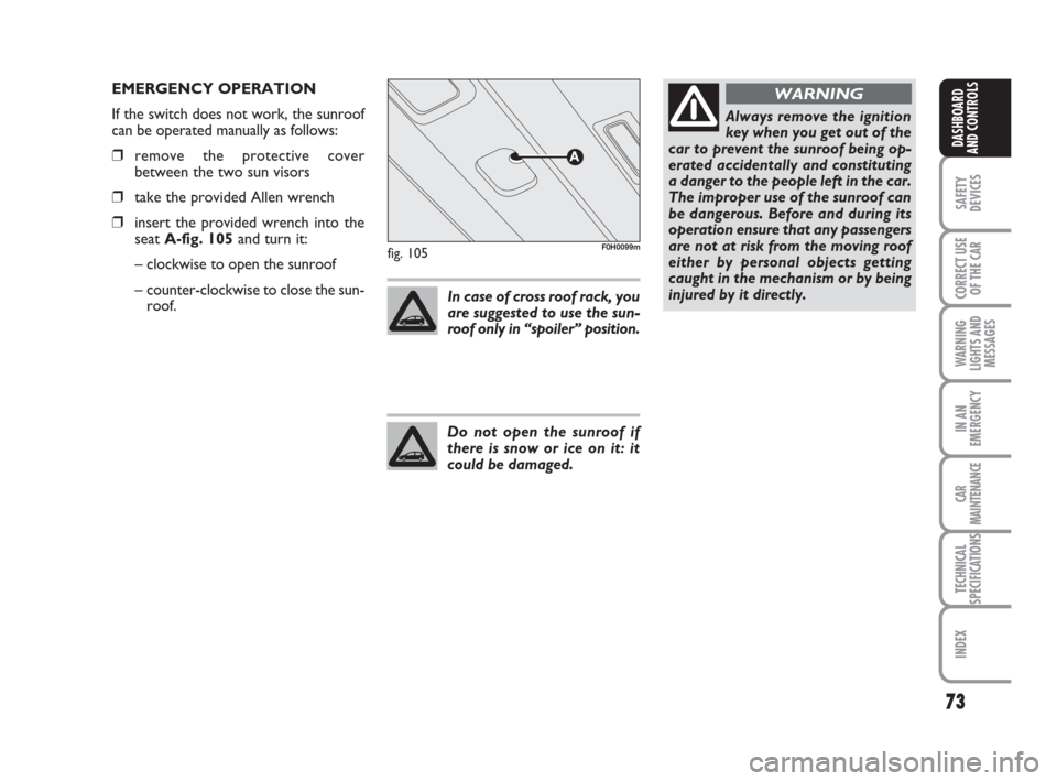
EMERGENCY OPERATION
If the switch does not work, the sunroof
can be operated manually as follows:
❒remove the protective cover
between the two sun visors
❒take the provided Allen wrench
❒insert the provided wrench into the
seat A-fig. 105and turn it:
– clockwise to open the sunroof
– counter-clockwise to close the sun-
roof.In case of cross roof rack, you
are suggested to use the sun-
roof only in “spoiler” position.
Do not open the sunroof if
there is snow or ice on it: it
could be damaged.
Always remove the ignition
key when you get out of the
car to prevent the sunroof being op-
erated accidentally and constituting
a danger to the people left in the car.
The improper use of the sunroof can
be dangerous. Before and during its
operation ensure that any passengers
are not at risk from the moving roof
either by personal objects getting
caught in the mechanism or by being
injured by it directly.
WARNING
036-092 idea GB 1 ed 10-07-2008 16:12 Pagina 73
Page 77 of 210
76
SAFETY
DEVICES
CORRECT USE
OF THE CAR
WARNING
LIGHTS AND
MESSAGES
IN AN
EMERGENCY
CAR
MAINTENANCE
TECHNICAL
SPECIFICATIONS
INDEX
DASHBOARD
AND CONTROLS
BOOT
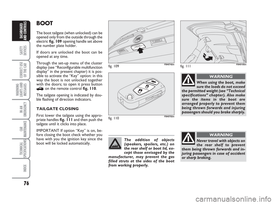
The boot tailgate (when unlocked) can be
opened only from the outside through the
electric fig. 109opening handle set above
the number plate holder.
If doors are unlocked the boot can be
opened at any time.
Through the set-up menu of the cluster
display (see “Reconfigurable multifunction
display” in the present chapter) it is pos-
sible to activate the “Key” option: in this
way the boot is not unlocked together
with the doors; to open it press button
Ron the remote control fig. 110.
The tailgate opening is indicated by dou-
ble flashing of direction indicators.
TAILGATE CLOSING
First lower the tailgate using the appro-
priate handles fig. 111and then push the
tailgate until it clicks into place.
IMPORTANT If option “Key” is on, be-
fore closing the boot check whether you
have with you the ignition key since the
boot will be locked automatically.
fig. 109F0H0742m
fig. 110F0H0702m
The addition of objects
(speakers, spoilers, etc.) on
the rear shelf or boot lid, ex-
cept those envisaged by the
manufacturer, may prevent the gas
filled struts at the sides of the boot
from working properly.
When using the boot, make
sure the loads do not exceed
the permitted weight (see “Technical
specifications” chapter). Also make
sure the items in the boot are
arranged properly to prevent them
being thrown forwards and injuring
passengers should you brake sharply.
WARNING
Never travel with objects on
the rear shelf to prevent
them being thrown forwards and in-
juring passengers in case of accident
or sharp braking.
WARNING
fig. 111F0H0105m
036-092 idea GB 1 ed 10-07-2008 16:12 Pagina 76
Page 78 of 210
77
SAFETY
DEVICES
CORRECT USE
OF THE CAR
WARNING
LIGHTS AND
MESSAGES
IN AN
EMERGENCY
CAR
MAINTENANCE
TECHNICAL
SPECIFICATIONS
INDEX
DASHBOARD
AND CONTROLS
EMERGENCY OPENING OF
TAILGATE
To succeed in opening the tailgate from
the inside, should the car battery be flat,
or because of a defect of the electric lock
of the tailgate, proceed as follows (refer
to “Extending the boot” in this section):
❒remove the rear head restraints;
❒tilt seat backrests to “table” configu-
ration;
❒tilt cushion / backrest completely.
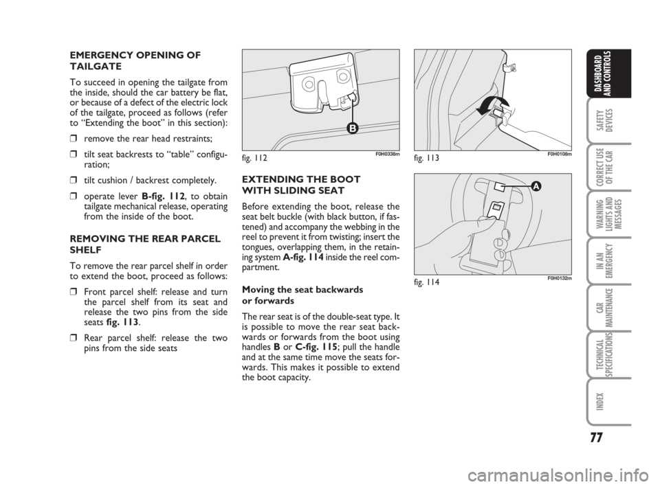
❒operate lever B-fig. 112, to obtain
tailgate mechanical release, operating
from the inside of the boot.
REMOVING THE REAR PARCEL
SHELF
To remove the rear parcel shelf in order
to extend the boot, proceed as follows:
❒Front parcel shelf: release and turn
the parcel shelf from its seat and
release the two pins from the side
seats fig. 113.
❒Rear parcel shelf: release the two
pins from the side seatsEXTENDING THE BOOT
WITH SLIDING SEAT
Before extending the boot, release the
seat belt buckle (with black button, if fas-
tened) and accompany the webbing in the
reel to prevent it from twisting; insert the
tongues, overlapping them, in the retain-
ing system A-fig. 114inside the reel com-
partment.
Moving the seat backwards
or forwards
The rear seat is of the double-seat type. It
is possible to move the rear seat back-
wards or forwards from the boot using
handles Bor C-fig. 115; pull the handle
and at the same time move the seats for-
wards. This makes it possible to extend
the boot capacity.
fig. 112F0H0338mfig. 113F0H0108m
fig. 114F0H0132m
036-092 idea GB 1 ed 10-07-2008 16:12 Pagina 77