right side FIAT MAREA 2000 1.G Owner's Manual
[x] Cancel search | Manufacturer: FIAT, Model Year: 2000, Model line: MAREA, Model: FIAT MAREA 2000 1.GPages: 330
Page 145 of 330
Marea- Marea Weekend
2000 range ©
Electrical equipment
Control module
55.
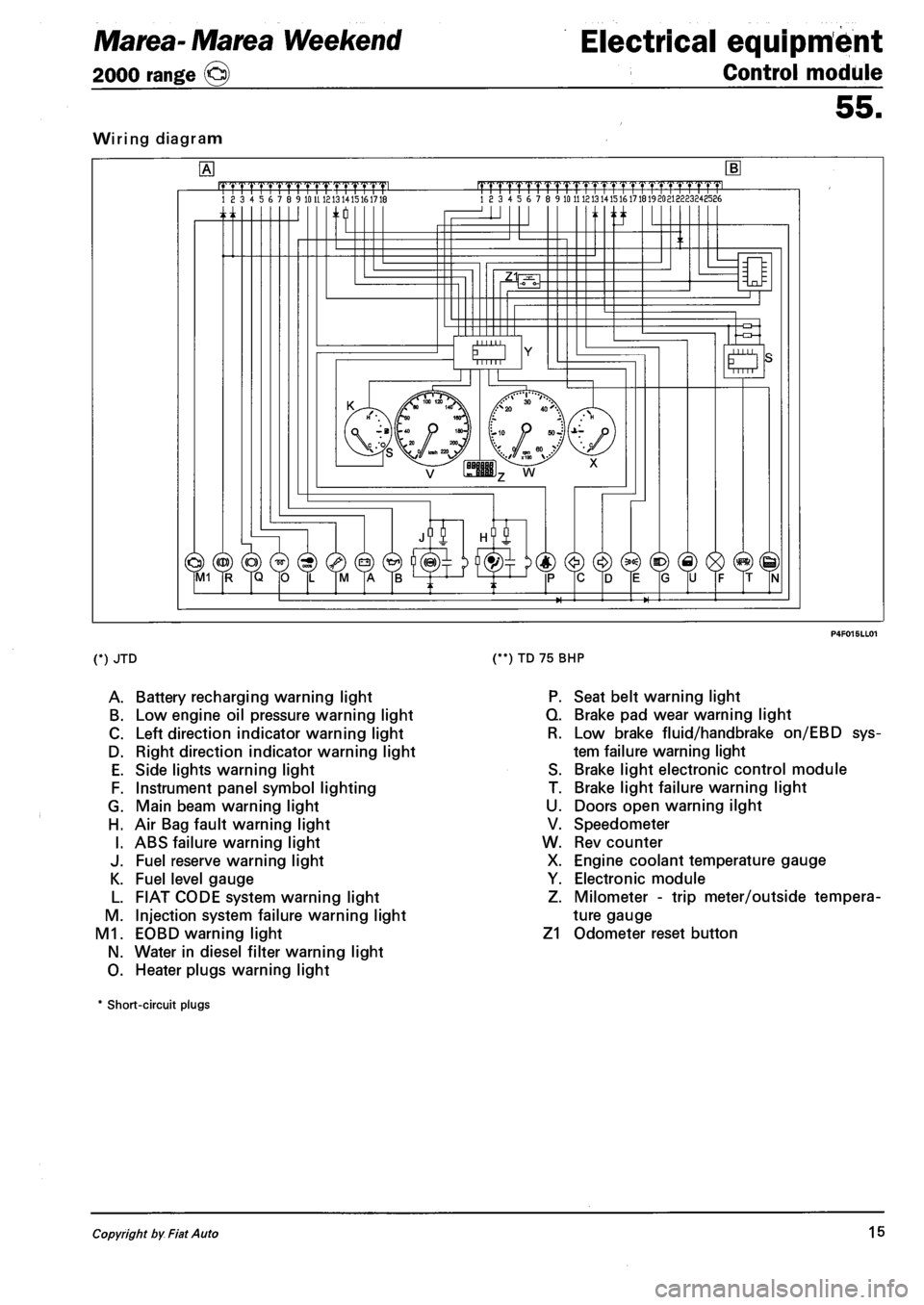
Wiring diagram
.mrmmmL 18 3 4 5 6 7 8 9 10 U 1213 1415161718 |TTTTrTrrrrTTTTT1.TTTTT1pmL 18 3 4 5 6 7 8 9 10 11 121314151617181920213223248586
n ti
O Mill
(*) JTD
A. Battery recharging warning light
B. Low engine oil pressure warning light
C. Left direction indicator warning light
D. Right direction indicator warning light
E. Side lights warning light
F. Instrument panel symbol lighting
G. Main beam warning light
H. Air Bag fault warning light
I. ABS failure warning light
J. Fuel reserve warning light
K. Fuel level gauge
L. FIAT CODE system warning light
M. Injection system failure warning light
M1. EOBD warning light
N. Water in diesel filter warning light
O. Heater plugs warning light
(**) TD 75 BHP
P. Seat belt warning light
Q. Brake pad wear warning light
R. Low brake fluid/handbrake on/EBD sys
tem failure warning light
S. Brake light electronic control module
T. Brake light failure warning light
U. Doors open warning ilght
V. Speedometer
W. Rev counter
X. Engine coolant temperature gauge
Y. Electronic module
Z. Milometer - trip meter/outside tempera
ture gauge
Z1 Odometer reset button
* Short-circuit plugs
Copyright by Fiat Auto 15
Page 146 of 330
Electrical equipment
Instrument panel
Marea- Marea Weekend
2000 range ©
55.
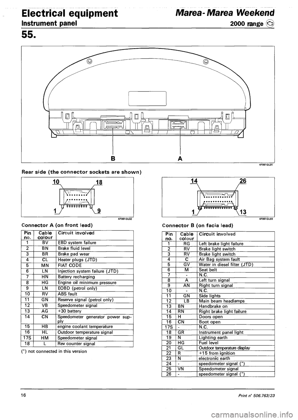
Rear side (the connector sockets are shown)
Connector A (on front lead) Connector B (on facia lead)
Pin no. Cable colour Circuit involved
1 BV EBD system failure
2 BN Brake fluid level
3 BR Brake pad wear
4 CL Heater plugs (JTD)
5 MN FIAT CODE
6 LN Injection system failure (JTD)
7 HN Battery recharging
8 HG Engine oil minimum pressure
9 LN EOBD (petrol only)
10 RV ABS fault
11 GN Reserve signal (petrol only)
12 VB Speedometer signal
13 AG +30 battery
14 CN Speedometer generator power supply
15 HB engine coolant temperature
16 HL Outdoor temperature signal
17S HM Speedometer signal
18 L Rev counter signal
(*) not connected in this version
Pin no. Cable colour Circuit involved
1 RG Left brake light failure
2 RV Brake light switch
3 RV Brake light switch
4 C Air Bag system fault
5 GV Water in diesel filter (JTD)
6 M Seat belt
7 -N.C.
8 A Left turn signal
9 AN Right turn signal
10 -N.C.
11 GN Side lights
12 LB Main beam headlamps
13 BN Handbrake on
14 RN Right brake light failure
15 H Doors open
16 CN Boot open
17S -N.C.
18 GR Instrument panel light
19 N Lighting earth
20 HG Fuel level
21 GL Outdoor temperature display
22 R +15 from ignition
23 N electronic earth
24 -speedometer signal (*)
25 VN Speedometer signal
26 -speedometer signal (*)
16 Print n° 506.763/23
Page 147 of 330
Marea- Marea Weekend Electrical equipment
2000 range (Q) Control module
55.
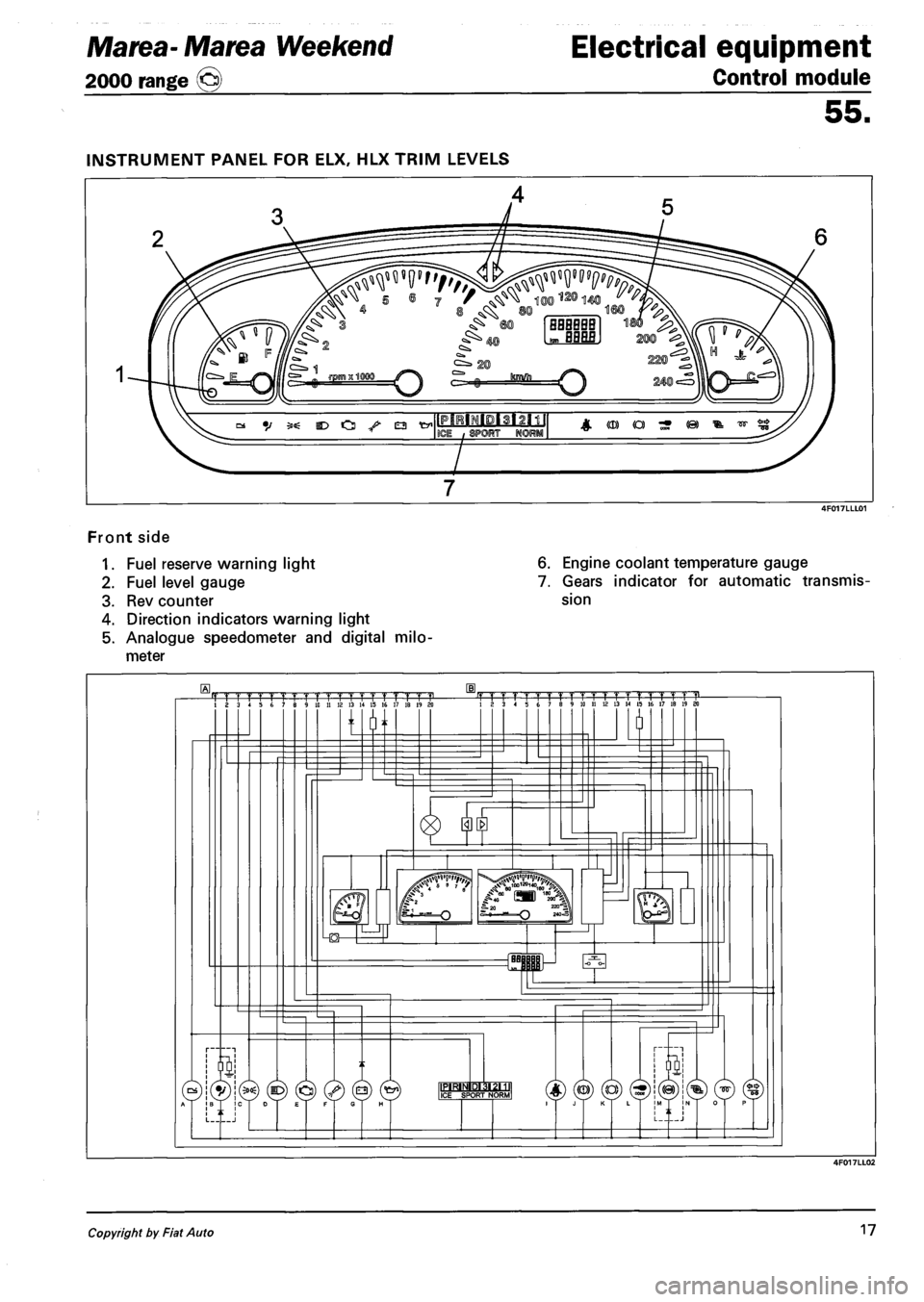
Front side
1. Fuel reserve warning light
2. Fuel level gauge
3. Rev counter
4. Direction indicators warning light
5. Analogue speedometer and digital milo
meter
6. Engine coolant temperature gauge
7. Gears indicator for automatic transmis
sion
Copyright by Fiat Auto 17
Page 148 of 330
Electrical equipment
Control module
Marea- Marea Weekend
2000 range ©
55.
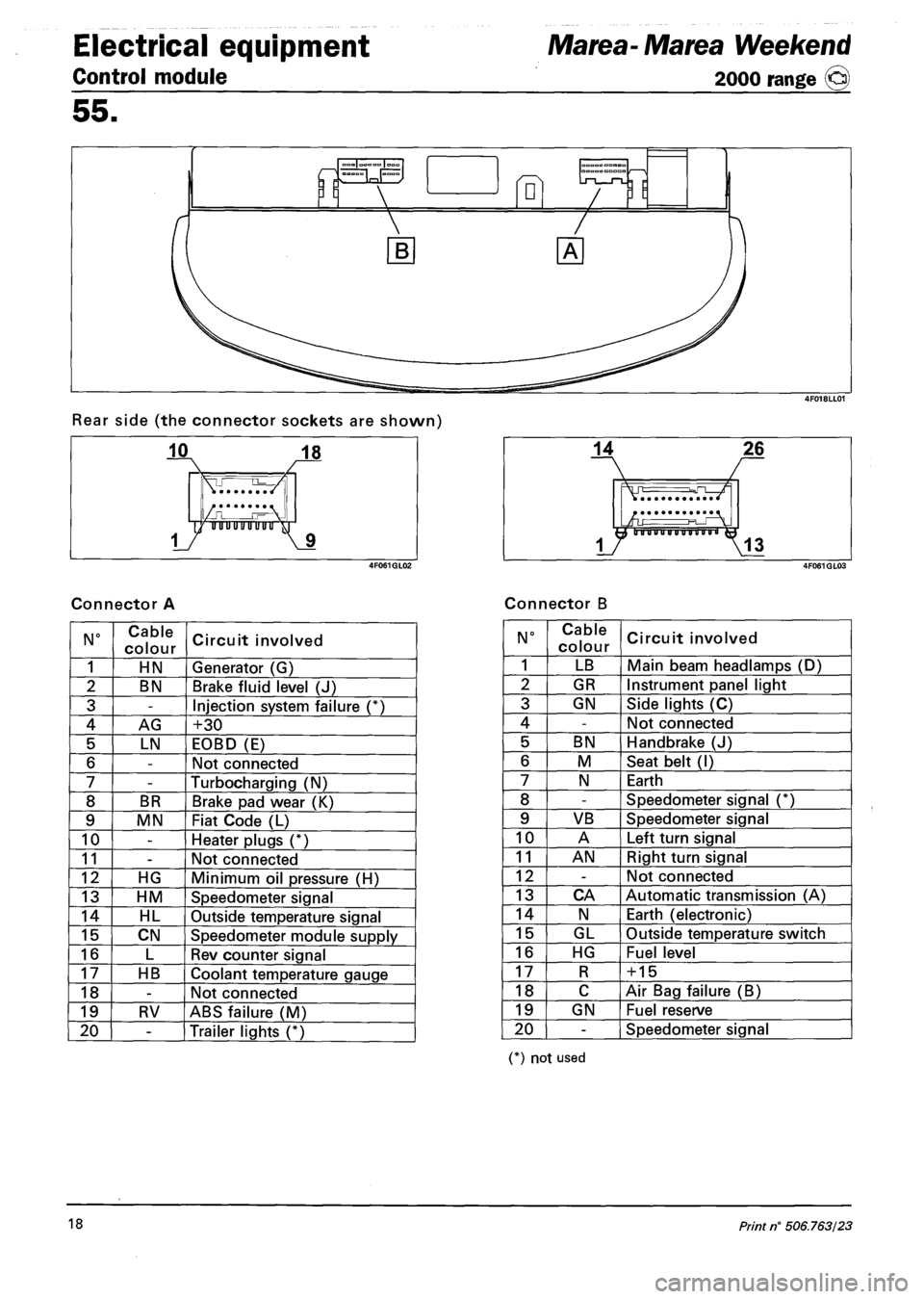
Rear side (the connector sockets are shown)
Connector A Connector B
N° Cable
colour Circuit involved
1 HN Generator (G)
2 BN Brake fluid level (J)
3 -Injection system failure (*)
4 AG +30
5 LN EOBD (E)
6 -Not connected
7 -Turbocharging (N)
8 BR Brake pad wear (K)
9 MN Fiat Code (L)
10 -Heater plugs (*)
11 -Not connected
12 HG Minimum oil pressure (H)
13 HM Speedometer signal
14 HL Outside temperature signal
15 CN Speedometer module supply
16 L Rev counter signal
17 HB Coolant temperature gauge
18 -Not connected
19 RV ABS failure (M)
20 -Trailer lights (*)
N° Cable
colour Circuit involved
1 LB Main beam headlamps (D)
2 GR Instrument panel light
3 GN Side lights (C)
4 -Not connected
5 BN Handbrake (J)
6 M Seat belt (I)
7 N Earth
8 -Speedometer signal (*)
9 VB Speedometer signal
10 A Left turn signal
11 AN Right turn signal
12 -Not connected
13 CA Automatic transmission (A)
14 N Earth (electronic)
15 GL Outside temperature switch
16 HG Fuel level
17 R + 15
18 C Air Bag failure (B)
19 GN Fuel reserve
20 -Speedometer signal
(*) not used
18 Print n° 506.763/23
Page 177 of 330
Marea- Marea Weekend Electrical system
2000 range (§) Radio System
55.
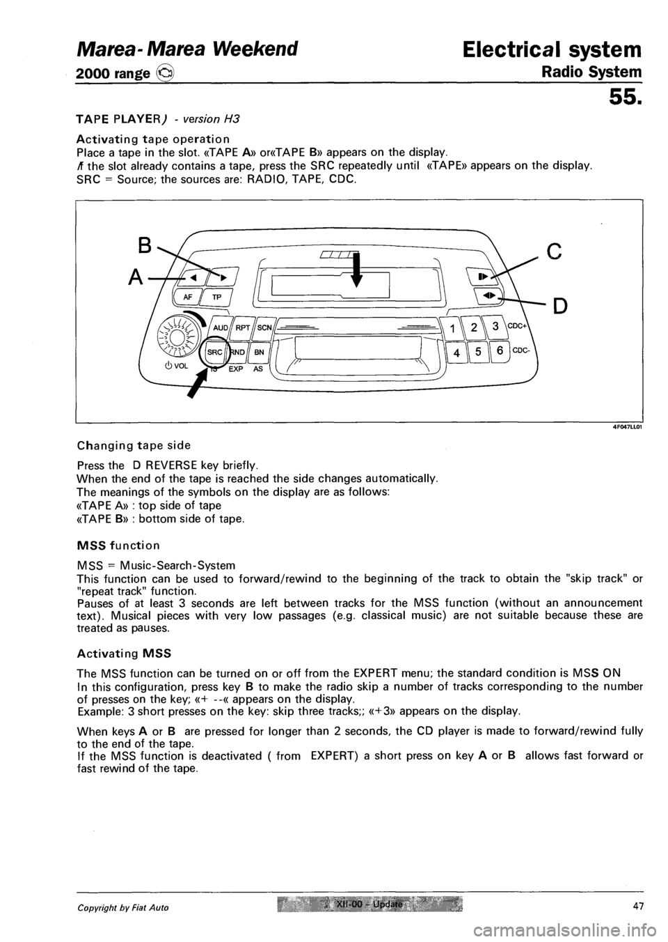
TAPE PLAYER; - version H3
Activating tape operation
Place a tape in the slot. «TAPE A» or«TAPE B» appears on the display.
/T the slot already contains a tape, press the SRC repeatedly until «TAPE» appears on the display.
SRC = Source; the sources are: RADIO, TAPE, CDC.
4F047LL01
Changing tape side
Press the D REVERSE key briefly.
When the end of the tape is reached the side changes automatically.
The meanings of the symbols on the display are as follows:
«TAPE A» : top side of tape
«TAPE B» : bottom side of tape.
MSS function
MSS = Music-Search-System
This function can be used to forward/rewind to the beginning of the track to obtain the "skip track" or
"repeat track" function.
Pauses of at least 3 seconds are left between tracks for the MSS function (without an announcement
text). Musical pieces with very low passages (e.g. classical music) are not suitable because these are
treated as pauses.
Activating MSS
The MSS function can be turned on or off from the EXPERT menu; the standard condition is MSS ON
In this configuration, press key B to make the radio skip a number of tracks corresponding to the number
of presses on the key; «+ --« appears on the display.
Example: 3 short presses on the key: skip three tracks;; «+3» appears on the display.
When keys A or B are pressed for longer than 2 seconds, the CD player is made to forward/rewind fully
to the end of the tape.
If the MSS function is deactivated ( from EXPERT) a short press on key A or B allows fast forward or
fast rewind of the tape.
Copyright by Fiat Auto Xfl-00 - Update 47
Page 179 of 330
Marea-Marea Weekend
2000 range ©
Electrical system
Radio System
55.
MULTIPLE COMPACT DISC PLAYER (CD changer)
The radio set (in H4 and H3 versions) is designed to work with compatible compact disc players avail
able from the Fiat Accessory range.
The Fiat Accessory range player comes with a loader that can hold up to 6 CDs.
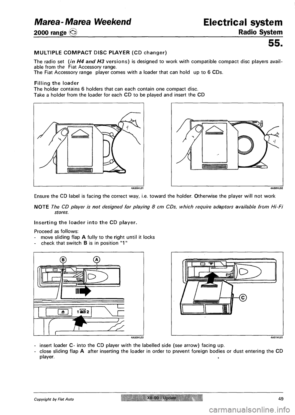
Filling the loader
The holder contains 6 holders that can each contain one compact disc.
Take a holder from the loader for each CD to be played and insert the CD
Ensure the CD label is facing the correct way, i.e. toward the holder. Otherwise the player will not work
NOTE The CD player is not designed for playing 8 cm CDs, which require adaptors available from Hi-Fi
stores.
Inserting the loader into the CD player.
Proceed as follows:
- move sliding flap A fully to the right until it locks
- check that switch B is in position "1"
- insert loader C- into the CD player with the labelled side (see arrow) facing up.
- close sliding flap A after inserting the loader in order to prevent foreign bodies or dust entering the CD
player.
Copyright by Fiat Auto XII-00 Update 49
Page 181 of 330
Marea-Marea Weekend Electrical system
2000 range (§) Radio System
55.
Repetition of a CD (REPEAT)
To repeat the current CD continously: press the RPT key for longer than 2 seconds: "RPT CD" appears on
the display.
A different CD may be selected. To suspend the function, press the RPT key again for longer than 2 sec
onds: «RPT MAG» appears on the display.
Selecting tracks in a random sequence (TRACK RANDOM)
To start the random track search:
press the RND key: "RND ON" appears on the display. The selected CD tracks are played in a random se
quence.
Press the RND key again to end the random track search: "RND OFF" appears on the display.
NOTE: The TRACK RANDOM function cannot be combined with the TRACK REPEAT and CD REPEAT
functions.
Concluding CD operation
Press the EJECT key
Alternatively, press the SRC to listen to the radio again
ADVICE AND PRECAUTIONS
RECEPTION CONDITIONS
The reception conditions will vary greatly while driving.
Reception can be affected by mountains, buildings or bridges especialy when far away from the transmit
ter of the station you are listening to.
Note: when listening to traffic information (TA), the volume may rise considerably compared to normal
levels.
MAINTENANCE
The radio is built for long-term use without any special maintenance requirements.
If necessary, clean the panel with a soft, antistatic cloth. Cleaning and polishing products could damage
the surface.
TAPES
For optimal playing conditions:
- do not use poor quality tapes, with deformations or peeling labels;
- do not leave the tape inside the radio when not in use;
- do not introduce any objects into the cassette slot;
- do not expose the tapes to sunlight, excessive temperature or high moisture levels;
- replace the tapes in their cases after use;
- dirt on the playing heads caused by tapes could eventually lead to a reduction in high tones during
playing. It is therefore advisable to clean the playing heads at intervals using a special non-abrasive
head cleaning tape;
- it is preferable to C60 tapes or in the worst case C90 tapes to ensure optimum playing quality at all
times. The very fine tape contained in very long cassettes could also break very easily;
- avoid inserting cassettes with loose tapes, particularly if C90, because the tape could emerge and block
the mechanism. If the radio detects a loose tape or similar problems, the cassette is in any case auto
matically ejected;
- do not lubricate the tape mechanism;
- do not touch the playing heads with magnetic or hard items.
Copyright by Fiat Auto XII 00 - Update 51
Page 184 of 330
Marea-Marea Weekend Electrical system
2000 range ©> Wiring diagrams
55.
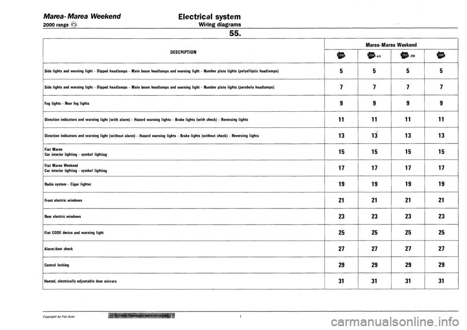
DESCRIPTION
Marea-Marea Weekend
DESCRIPTION JTD
SIDE LIGHTS AND WARNING LIGHT - DIPPED HEADLAMPS - MAIN BEAM HEADLAMPS AND WARNING LIGHT - NUMBER PLATE LIGHTS (POLYELLIPTIC HEADLAMPS) 5 5 5 5
SIDE LIGHTS AND WARNING LIGHT - DIPPED HEADLAMPS - MAIN BEAM HEADLAMPS AND WARNING LIGHT - NUMBER PLATE LIGHTS (PARABOLA HEADLAMPS) 7 7 7 7
FOG LIGHTS - REAR FOG LIGHTS 9 9 9 9
DIRECTION INDICATORS AND WARNING LIGHT (WITH ALARM) - HAZARD WARNING LIGHTS - BRAKE LIGHTS (WITH CHECK) - REVERSING LIGHTS 11 11 11 11
DIRECTION INDICATORS AND WARNING LIGHT (WITHOUT ALARM) - HAZARD WARNING LIGHTS - BRAKE LIGHTS (WITHOUT CHECK) - REVERSING LIGHTS 13 13 13 13
FIAT MAREA
CAR INTERIOR LIGHTING - SYMBOL LIGHTING 15 15 15 15
FIAT MAREA WEEKEND
CAR INTERIOR LIGHTING - SYMBOL LIGHTING 17 17 17 17
RADIO SYSTEM - CIGAR LIGHTER 19 19 19 19
FRONT ELECTRIC WINDOWS 21 21 21 21
REAR ELECTRIC WINDOWS 23 23 23 23
FIAT CODE DEVICE AND WARNING LIGHT 25 25 25 25
ALARM/DOOR CHECK 27 27 27 27
CENTRAL LOCKING 29 29 29 29
HEATED, ELECTRICALLY ADJUSTABLE DOOR MIRRORS 31 31 31 31
Copyright by Fiat Auto '' XI Supersedes previous verster*.
Page 191 of 330
Marea-Marea Weekend
2000 range ©
Electrical equipment
Wiring diagrams
55.
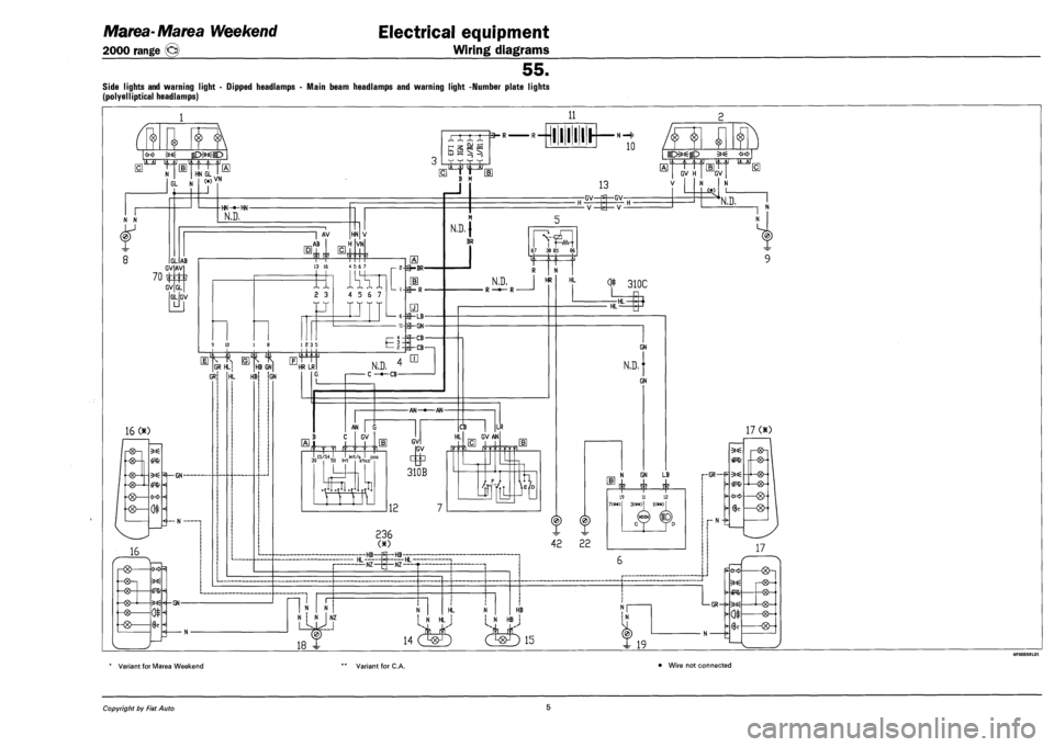
SIDE LIGHTS AND WARNING LIGHT - DIPPED HEADLAMPS - MAIN BEAM HEADLAMPS AND WARNING LIGHT -NUMBER PLATE LIGHTS
(POLYELLIPTICAL HEADLAMPS)
1 11
<»» a»< gD-:oo:-iD
'm iH, ,i ,|j ' N HNGL...
XX XX =J S§5N
3-R'
jjj '3r
10
6L N
N N
k
GL AB GV AV
70 %
GV GL
GV
16 <*)
-®-|
-HGL-
israp. V M
-GN-
J
B M
H 1 1 H GV H GV
HN-»-HN-
N.D,
m
1 AV
A6 HN
H VN
13 16
2 3
rr
4 5 6 7 _ 2-feHBR-
1] L 1-3-R-5
u
4 5 6 7
9 10 1 12 3 5
GR HL j
GR HL HB {GN
— GN
N
HB GN] LE
El:
HR LR
1— 6-3-LB-
n-H-GN-
-CB-
-CB-
N.D. < • C —»-CB-
m
13
-GV^ f— GV-
- V—1 — V-
N.D. |
BR 87 30 85 86
N.D.
• R —•— R •
HR
-AN--AN-
J 15/54 J lii
AN | G
GV
15/54 J. ,'krt/a ' pos
mm
3
12
CB LR
HL GV
OB
GV AN
A
Li i
HL 0* 310C
HL HL-
GN
N.D,
GN
236
42 22
N GN LB
j|2 £$2 £|L
3(*a0 K«x)
(j00? (pD) cSr YD
HL •HB-H~ HB-;
— NZ—-— NZ-HL
-f
n N | N
18 X
NT
NZ I I
f
HL N
i i i
HB
! N HL j N HB
ji E!L J£—&
14 (Wj (W) 15 X 19
N
^4
13
N.D,
17 <*)
1—GR —^ ;00;
(ft
0
H2H
-
HG>-
Variant for Marea Weekend Variant for C.A. Wire not connected
Copyright by Fiat Auto 5
Page 192 of 330
4F006ML01
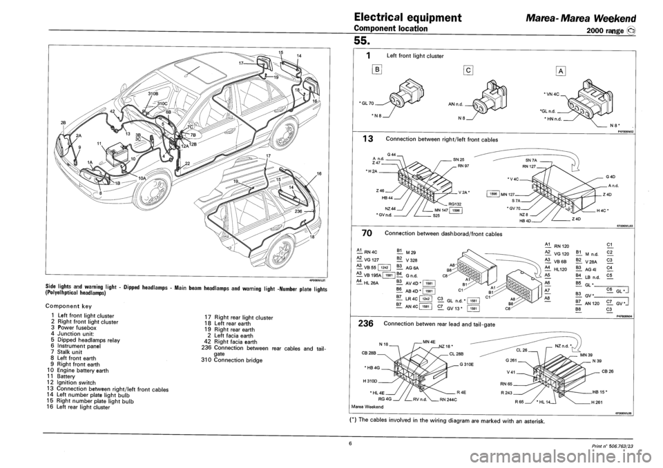
SIDE LIGHTS AND WARNING LIGHT - DIPPED HEADLAMPS - MAIN BEAM HEADLAMPS AND WARNING LIGHT -NUMBER PLATE LIQHTS (POLYELHPTICAL HEADLAMPS) r »
Component key
1 Left front light cluster
2 Right front light cluster
3 Power fusebox
4 Junction unit:
5 Dipped headlamps relay
6 Instrument panel
7 Stalk unit
8 Left front earth
9 Right front earth
10 Engine battery earth
11 Battery
12 Ignition switch
13 Connection between right/left front cables
14 Left number plate light bulb
15 Right number plate light bulb
16 Left rear light cluster
17 Right rear light cluster
18 Left rear earth
19 Right rear earth
2 Left facia earth
42 Right facia earth
236 Connection between rear cables and tail
gate
310 Connection bridge
Electrical equipment
Component location
Marea-Marea Weekend
2000 range (§)
55.
Left front light cluster
B
'GL70
N8'
1 3 Connection between right/left front cables
•H2A
NZ44
* GV n.d.
70 Connection between dashborad/front cables
A1
— RN 4C
— VG 127
B1 M29
^1 VB 55 | 1242
A3
— V328
11 AG6A
VB 195A | 1581 |B4 GN D
^1 HL 26A 11 AV 4D * I 1581
?! AB 4D"
11 LR 4C f
1581
1242
1Z_ AN4C| 1581
RN 120
VG 120
^1 VB6B
£1 HL120
B1 M n.d.
11 V28A
11 AG 41
11 LB n.d.
21
C2_
21
21
C5
B5 GL"
21 GL n.d.
2L GV13*
11 GV*
!T_ AN 120
B8
C6 GL •
2Z_ GV*J
21 P4F808NO4
236 Connection betwen rear lead and tail-gate
CB 28B
CB 26
* HL 4E
RG 4G
Marea Weekend
(*) The cables involved in the wiring diagram are marked with an asterisk.
6 Print n° 506.763/23