Heat FIAT MAREA 2000 1.G Workshop Manual
[x] Cancel search | Manufacturer: FIAT, Model Year: 2000, Model line: MAREA, Model: FIAT MAREA 2000 1.GPages: 330
Page 38 of 330
Marea- Marea Weekend Technical Data
2000 range (§) Engine: supercharging
OO.io
SUPERCHARGING Turbocharger operated by exhaust gases with waste-gate pressure valve and air/air
heat exchanger (intercooler)
COOLING
Turbocharger: type Garret GT 17 variable geometry
Maximum supercharging pressure 1 bar
6
5
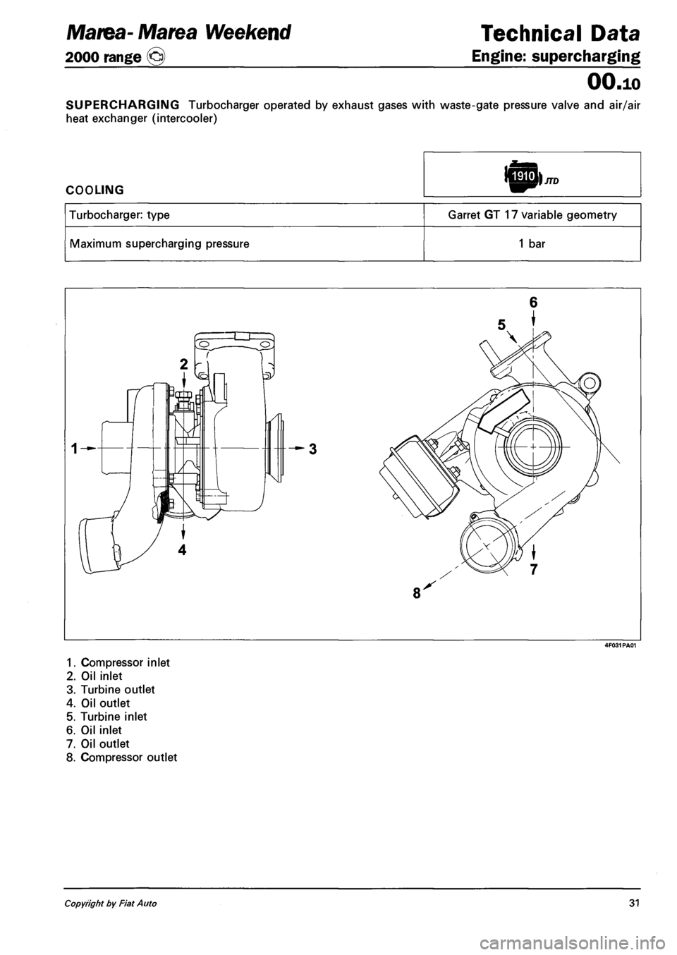
1. Compressor inlet
2. Oil inlet
3. Turbine outlet
4. Oil outlet
5. Turbine inlet
6. Oil inlet
7. Oil outlet
8. Compressor outlet
Copyright by Fiat Auto 31
Page 68 of 330
Marea- Marea Weekend • *» Engine
2000 range (§) Fuel feed system
10.
Pages
FUEL FEED SYSTEM
- Engine management system 1
- Diagram showing engine exhaust assem
bly 1
- Fuel anti-evaporation system ~2
- Location of diagnostic socket 2
- Location of injection/ignition system
components in the engine compartment 3
- Front Lambda sensor . 4
- Rear Lambda sensor 4
- Catalytic converter heat shield 5
- Catalytic converter 5
- Exhaust manifold 6
- Electric fuel pump with level sender unit 7
Copyright by Fiat Auto
Page 69 of 330
Marea- Marea Weekend • ^ Engine
2000 range (Q) Fuel feed system
10.
ENGINE MANAGEMENT SYSTEM
The Marea-Marea Weekend 1596 16v has a 4 cylinder in line engine, with 16 valves, 1596 cc, twin over
head camshaft and a Marelli IAW 4EF integrated electronic injection/ignition system.
The fuel system differs from the one described for the 1581 16v "99 range" version through the addition
of several variants to make it compatible with the EEC Stage 3 EOBD regulations.
The main modifications to the system can be summarized as follows:
- Engine management control unit with IAW 4EF
- Catalytic converter near the exhaust manifold to take maximum advantage of the heat of the gases.
- Two Lambda senors, one upstream (front) and one downstream (rear) which check the quality of the
exhaust gases and the operation of the catalyzer.
- Adoption of a timing sensor on the inlet side timing pulley.
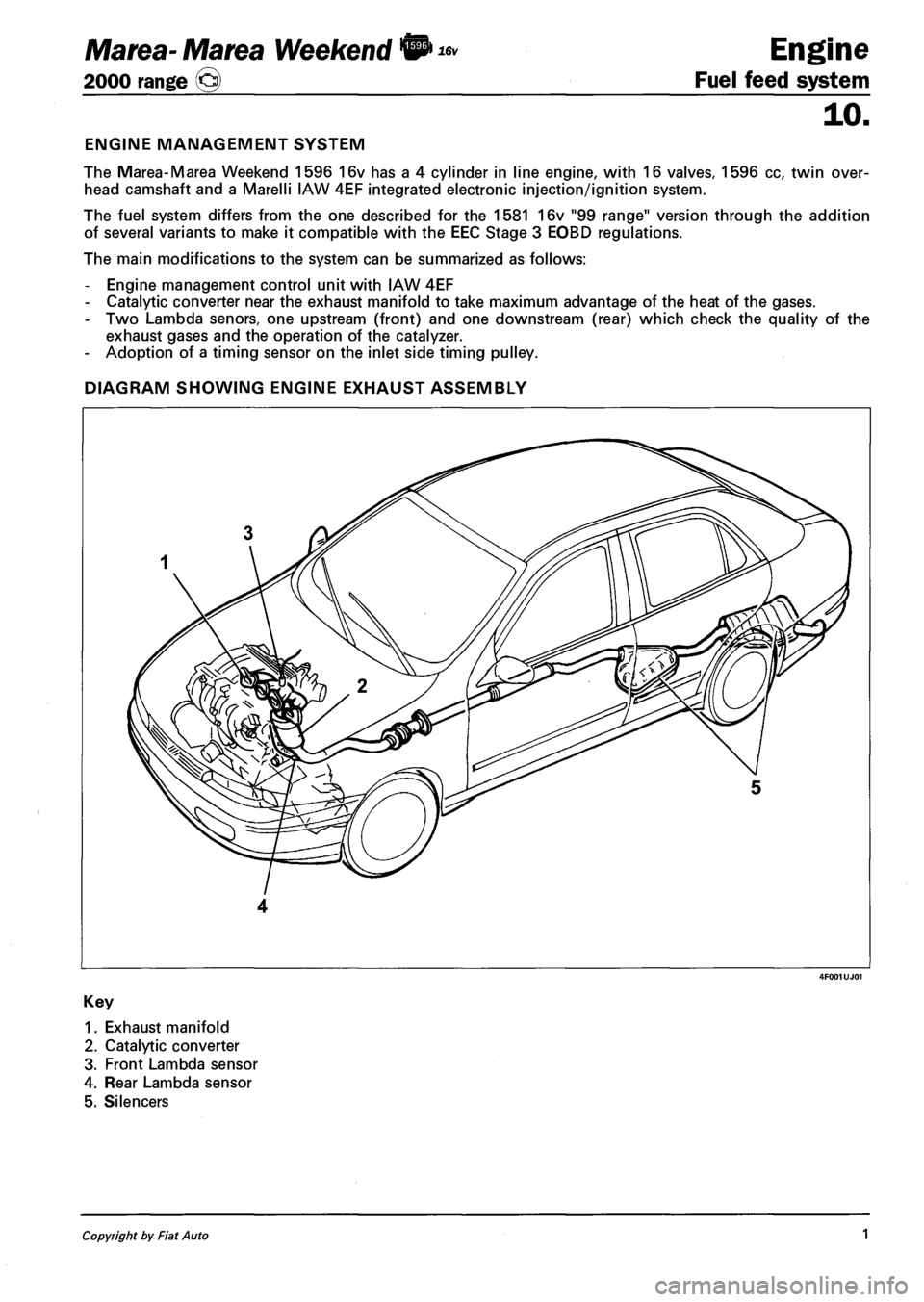
DIAGRAM SHOWING ENGINE EXHAUST ASSEMBLY
1. Exhaust manifold
2. Catalytic converter
3. Front Lambda sensor
4. Rear Lambda sensor
5. Silencers
Copyright by Fiat Auto 1
Page 73 of 330
Marea-Marea Weekend
2000 range ©
Engine
Fuel feed system
10.
CATALYTIC CONVERTER HEAT SHIELD
Removing-refitting
- Position the vehicle on a lift and disconnect
the negative battery terminal.
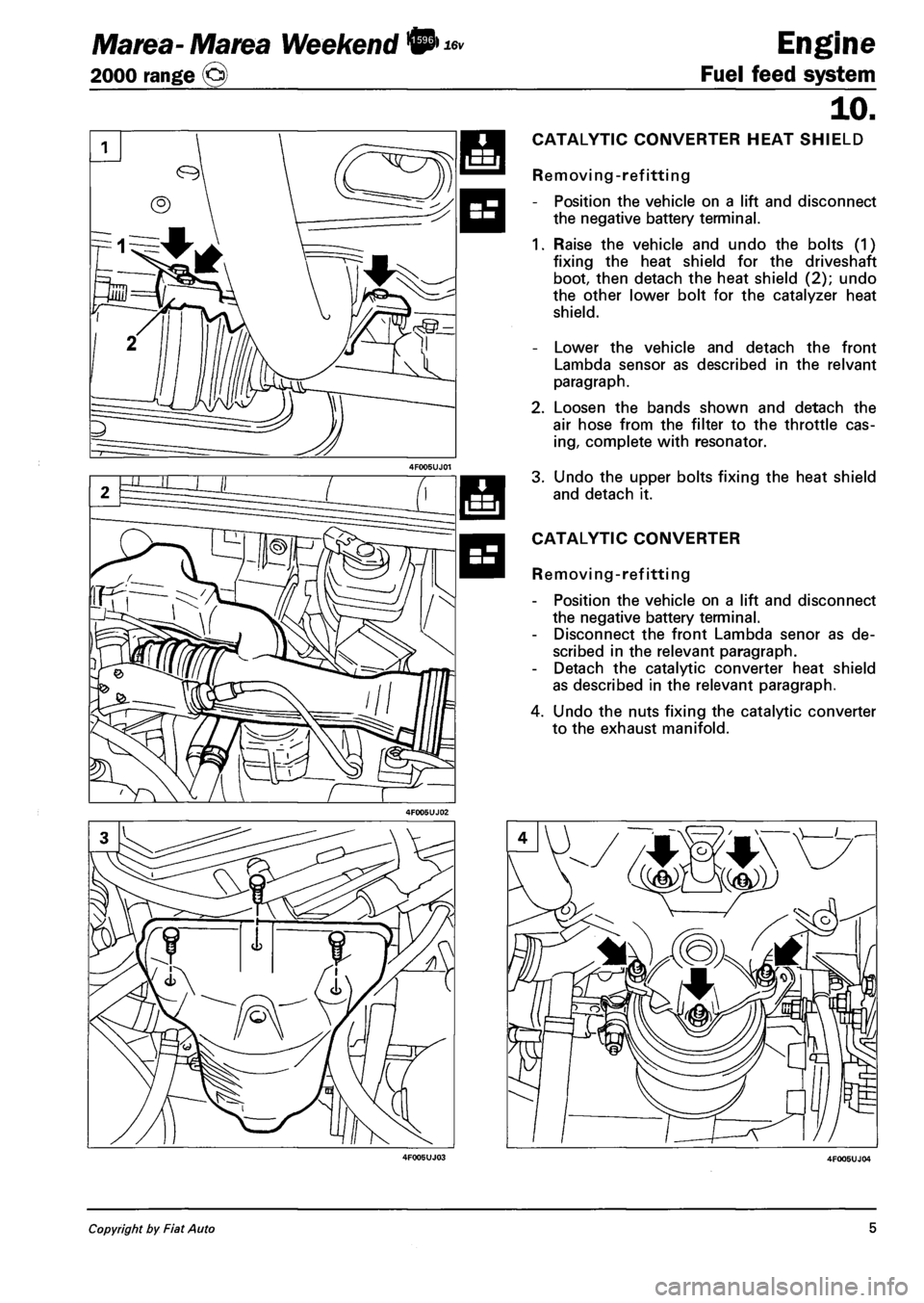
1. Raise the vehicle and undo the bolts (1)
fixing the heat shield for the driveshaft
boot, then detach the heat shield (2); undo
the other lower bolt for the catalyzer heat
shield.
- Lower the vehicle and detach the front
Lambda sensor as described in the relvant
paragraph.
2. Loosen the bands shown and detach the
air hose from the filter to the throttle cas
ing, complete with resonator.
3. Undo the upper bolts fixing the heat shield
and detach it.
CATALYTIC CONVERTER
Removing-refitting
- Position the vehicle on a lift and disconnect
the negative battery terminal.
- Disconnect the front Lambda senor as de
scribed in the relevant paragraph.
- Detach the catalytic converter heat shield
as described in the relevant paragraph.
4. Undo the nuts fixing the catalytic converter
to the exhaust manifold.
Copyright by Fiat Auto 5
Page 74 of 330
Engine
Fuel feed system
16v Marea- Marea Weekend ©
2000 range @
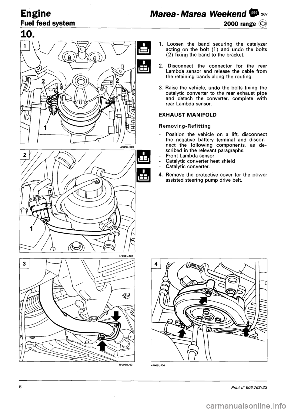
1. Loosen the band securing the catalyzer
acting on the bolt (1) and undo the bolts
(2) fixing the band to the bracket.
2. Disconnect the connector for the rear
Lambda sensor and release the cable from
the retaining bands along the routing.
3. Raise the vehicle, undo the bolts fixing the
catalytic converter to the rear exhaust pipe
and detach the converter, complete with
rear Lambda sensor.
EXHAUST MANIFOLD
Removing-Refitting
- Position the vehicle on a lift, disconnect
the negative battery terminal and discon
nect the following components, as de
scribed in the relevant paragraphs.
- Front Lambda sensor
- Catalytic converter heat shield
- Catalytic converter.
4. Remove the protective cover for the power
assisted steering pump drive belt.
6 Print n° 506.763/23
Page 77 of 330
Marea- MareaWeekend • ** Engine
2000 range @ . . Index
10.
. Page
FUEL FEED SYSTEM
- Engine management system 1
- Location of injection/ignition system
components 2
- Location of diagnostic socket 2
- Removing-refitting accelorometer 3
- Removing-refitting front Lambda sensor 3
- Removing-refitting rear Lambda sensor 4
- Removing-refitting heat shield 5
- Removing-refitting catalytic converter 7
Copyright by Fiat Auto
Page 78 of 330
Marea- Marea Weekend & Engine
2000 range (§) Fuel feed system
ENGINE MANAGEMENT SYSTEM
Foreword
The Marea-Marea Weekend 1998 20v is equipped with a 5 cylinder in line engine with 20 valves, 1998
cc, twin overhead camshaft and a Bosch ME3.1 integrated electronic injection/ignition system.
The fuel system differs from the one described for the 1998 20v "99 range" version through the addition
of several variants to make it compatible with the EEC Stage 3 EOBD regulations.
The main modifications to the system can be summarized as follows:
- Catalytic converter near the exhaust manifold to take maximum advantage of the heat of the gases.
- Two Lambda sensors, one upstream (front) and one downstream (rear) which check the quality of the
exhaust gases and the operation of the catalyzer.
- Adoption of an accelerometre sensor on the right shock absorber turret, used to distinguish between
engine torque variations doe to the uneveness of the road surface and those due to failed ignition in
the combustion chamber (misfire).
- Adoption of a timing sensor on the inlet side timing pulley.
- Multi-purpose valve on the tank to prevent leaks.
- Adoption of raipd attachment connectors for the anti-evaporation system pipes.
- Cap on the fuel filler with an attachment cable.
For further information on the fuel system, refer to publication 507137.
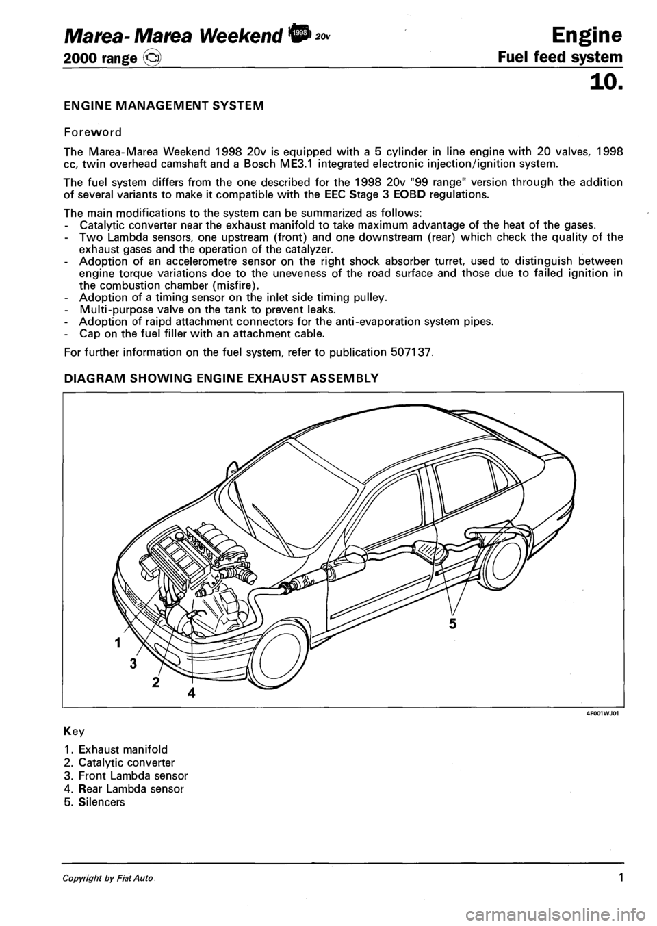
DIAGRAM SHOWING ENGINE EXHAUST ASSEMBLY
4F001WJ01
Key
1. Exhaust manifold
2. Catalytic converter
3. Front Lambda sensor
4. Rear Lambda sensor
5. Silencers
Copyright by Fiat Auto 1
Page 80 of 330
Marea- Marea Weekend •
2000 range ©
Engine
Fuel feed system
10.
REMOVING-REFITTING ACCELEROMETER
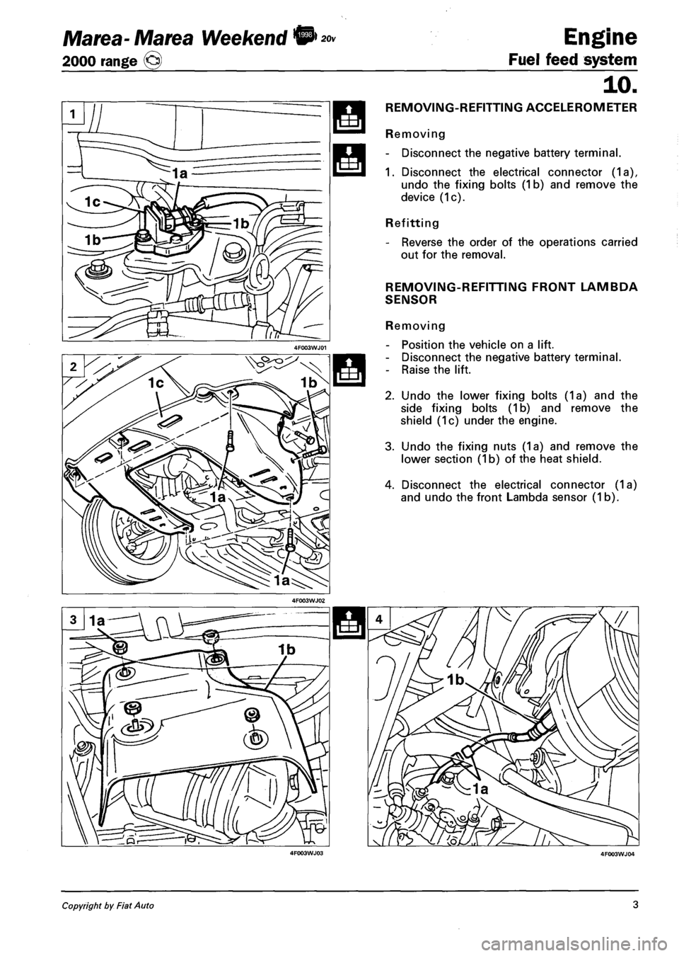
Removing
- Disconnect the negative battery terminal.
1. Disconnect the electrical connector (1a),
undo the fixing bolts (1b) and remove the
device (1c).
Refitting
- Reverse the order of the operations carried
out for the removal.
REMOVING-REFITTING FRONT LAMBDA
SENSOR
Removing
- Position the vehicle on a lift.
- Disconnect the negative battery terminal.
- Raise the lift.
2. Undo the lower fixing bolts (1a) and the
side fixing bolts (1b) and remove the
shield (1c) under the engine.
3. Undo the fixing nuts (1a) and remove the
lower section (1 b) of the heat shield.
4. Disconnect the electrical connector (1a)
and undo the front Lambda sensor (1b).
Copyright by Fiat Auto 3
Page 82 of 330
Marea-Marea Weekend •
2000 range (§)
4F005WJ02
Engine
Fuel feed system
10.
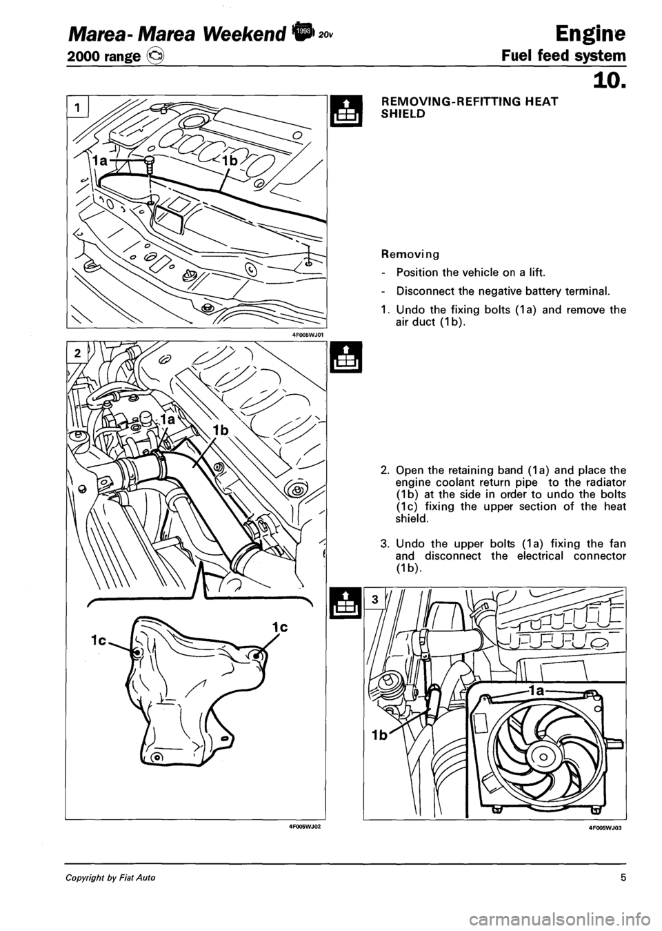
REMOVING-REFITTING HEAT
SHIELD
Removing
- Position the vehicle on a lift.
- Disconnect the negative battery terminal.
1. Undo the fixing bolts (1a) and remove the
air duct (1b).
2. Open the retaining band (1a) and place the
engine coolant return pipe to the radiator
(1b) at the side in order to undo the bolts
(1c) fixing the upper section of the heat
shield.
3. Undo the upper bolts (1a) fixing the fan
and disconnect the electrical connector
(1b).
4F005WJ03
Copyright by Fiat Auto 5
Page 83 of 330
Engine
Fuel feed system
20v Marea- Marea Weekend •
2000 range @
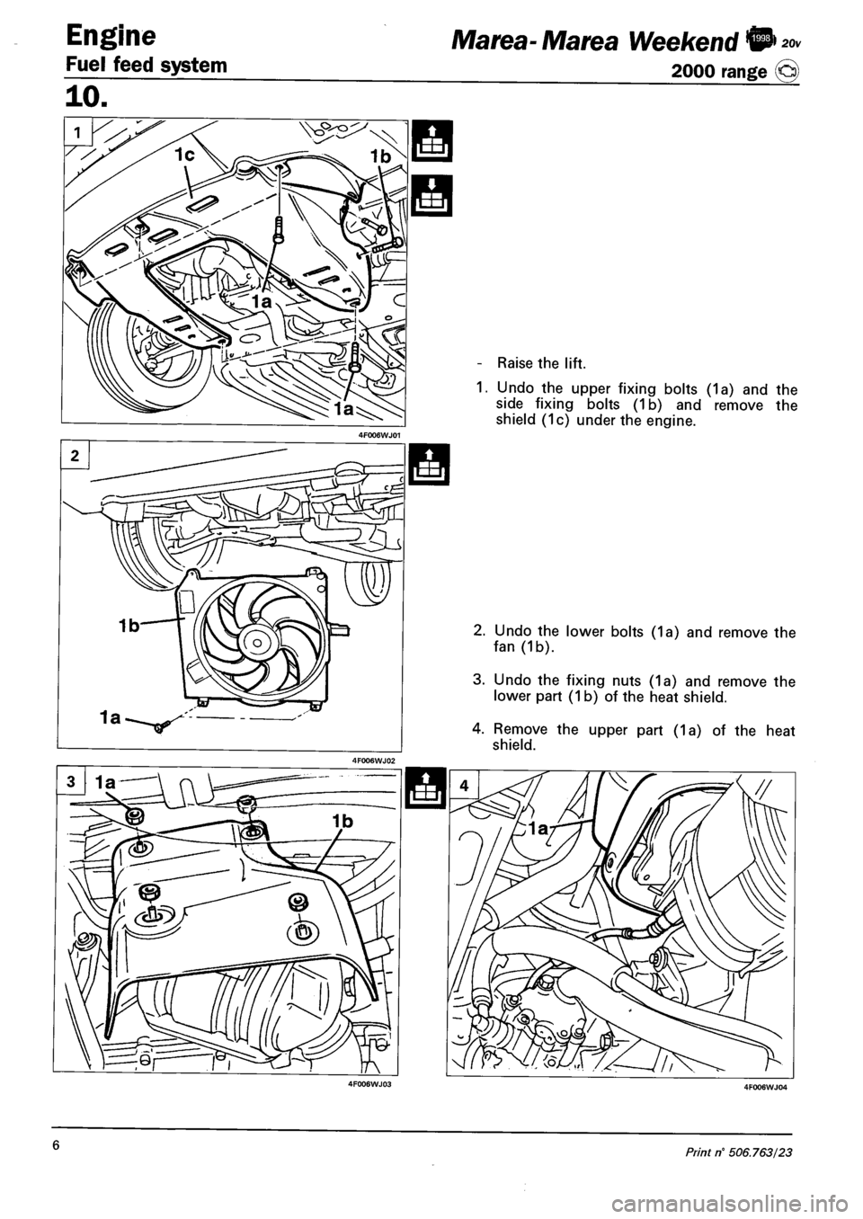
Raise the lift.
Undo the upper fixing bolts (1a) and the
side fixing bolts (1b) and remove the
shield (1c) under the engine.
2. Undo the lower bolts (1a) and remove the
fan (1b).
3. Undo the fixing nuts (1a) and remove the
lower part (1 b) of the heat shield.
4. Remove the upper part (1a) of the heat
shield.
6 Print n° 506.763/23