1910 jtd FIAT MAREA 2001 1.G User Guide
[x] Cancel search | Manufacturer: FIAT, Model Year: 2001, Model line: MAREA, Model: FIAT MAREA 2001 1.GPages: 330
Page 129 of 330
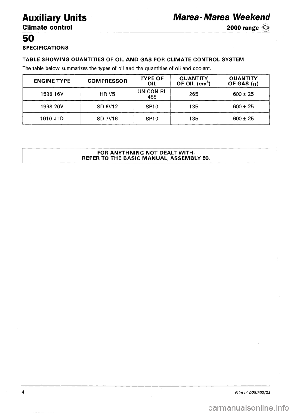
Auxiliary Units
Climate control
50
SPECIFICATIONS
TABLE SHOWING QUANTITIES OF OIL AND GAS FOR CLIMATE CONTROL SYSTEM
The table below summarizes the types of oil and the quantities of oil and coolant.
ENGINE TYPE COMPRESSOR TYPE OF
OIL
QUANTITY
OF OIL (cm3)
QUANTITY
OF GAS (g)
1596 16V HR V5 UNICON RL
488 265 600 ± 25
1998 20V SD6V12 SP10 135 600 ± 25
1910 JTD SD 7V16 SP10 135 600 ± 25
FOR ANYTHNING NOT DEALT WITH,
REFER TO THE BASIC MANUAL, ASSEMBLY 50.
Marea-Marea Weekend
2000 range ©
4 Print n' 506.763/23
Page 131 of 330
Marea- Marea Weekend
2000 range ©
Electrical equipment
Protection and security devices
55.
PROTECTION AND SAFETY DEVICES
All the vehicle supply lines were designed taking into account the most up-to-date directives in terms of
safety and protection, especially to prevent fires.
There are 2 types of protection:
- active protection, aims to reduce the causes of faults "at source"
- passive protection, aims to limit the effects of a fault as much as possible
The first category includes a carefully designed wiring layout with wires positioned and carefully anchored
on tracks that are repaired and protected if necessary.
The cables connected to the alternator and the motor were modified for this reason by adding protective
caps etc. A strengthened sheath was also introduced for some of the more exposed sections of wiring.
The passive protection includes all interventions to reduce faults due to high current (overload, short cir
cuit).
All system fuses were rated based on the nominal absorbtion of the loads activated at the same time, to
ensure intervention in cases of a clear short circuit.
The introduction of a box containing 4 maxifuses with other fuses connected on the outside means all
the supplies can be protected except for the cable that connects the battery to the starter motor and the
cable that connects the starter motor to the recharging alternator. These cables are therefore protected by a
strengthened supplementary sheath.
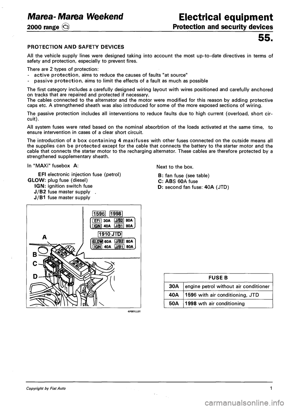
In "MAXI" fusebox A:
EFI electronic injection fuse (petrol)
GLOW: plug fuse (diesel)
IGN: ignition switch fuse
J/B2 fuse master supply .
J/B1 fuse master supply
Next to the box.
B: fan fuse (see table)
C: ABS 60A fuse
D: second fan fuse: 40A (JTD)
115961 1998
iFil 30A IJ/B21 BOA
fiGNl 4OA IJTBTI BOA
1910JTD
IGLOWl 60A P7B21 80A
MGNI 40A IJ/Bll 80A
FUSE B
30A engine petrol without air conditioner
40A 1596 with air conditioning, JTD
50A 1998 wth air conditioning
Copyright by Fiat Auto 1
Page 239 of 330
Marea-Marea Weekend
2000 range ©
Electrical equipment
Wiring diagrams
55.
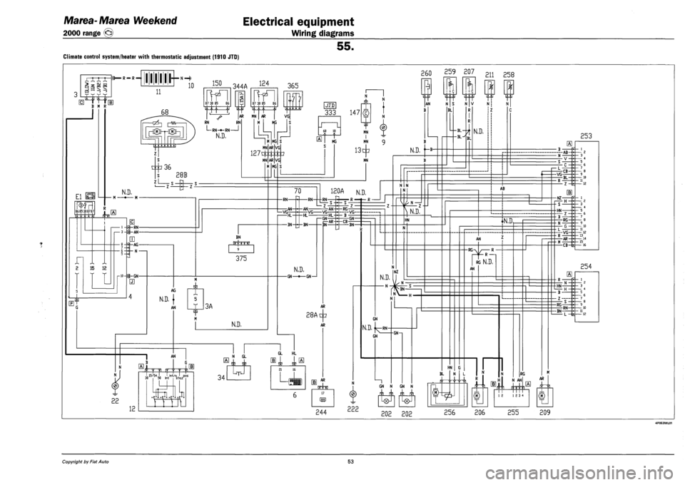
Climate control system/heater with thermostatic adjustment (1910 JTD)
XXX X
—J I—I _^ —£
3— R — R —
B M R
111111 *
260 259 207
11
10 150 344A 124
El la^SI
86 85 308787
t
n 1 1
68
frfl 87 30 85 86
-QZ5—| [—Wv-
frTI 87 30 85 86
365
RN RN
L-RN-fr-RN 1
N.D,
AR MN | AR | VG
M KG
c^36
N.D.
s 28B
LLki
MN
1271£
MN
MG
AR
AR
MG
15 12
1-9-RN-•3-p-AN-
rjj
|-AG-
I- N -
E
rw-p-GN-
m
BN
375
AG
N.D. |
AN 3A
N.D,
JTD
333 147
60 18
MG
VG
VG
MN I MN
13^
MN
TjZT
AN
B
1*1
N S
BL
N
N.D. '~B
70
-RN-
1—VG; -AN-
-RN-
120A N.D.
-AN-
^RN_-
Z
-HL
-BN-
VG VG--AN-
I—GN HL-
N.D.
-GN—•—GN—1
-RG-
-CB--GN-
BN-
VG
28A
AR
+
AR
AN
12
few
I 15/54 I I
.H
„„ 15/54 ' ,1, !nt/a J pos 30 50 Int s-tazH 34
N GL
JL
GL HL
21 16
L,
s JL
17
(55
244
^ N.D,
HN
N.D.
— N -
NZ
N
GN
N.D. j^RN-
GN
N
222
GN—i
- + c
w
211 258
N V
R
N.D.
HN G
BL
GN N GN N
n n
N
AB
N.D,
AN
-RG-R —
RG N,D,
AN
RG
N AN
202 202 256 206
12 12 3 4
255
253
-AB-
i— L
-VG CB-
BL-
-NZ-
- S -
-HN-
m
-RG-
|---VG-
-AR-
-CB-fe-
254
-HN-
- B -
- Z -
-RG
-BN-RN-
L —fe-
AR
209
Copyright by Fiat Auto 53
Page 240 of 330
Electrical equipment
Component location
Marea- Marea Weekend
2000 range ®
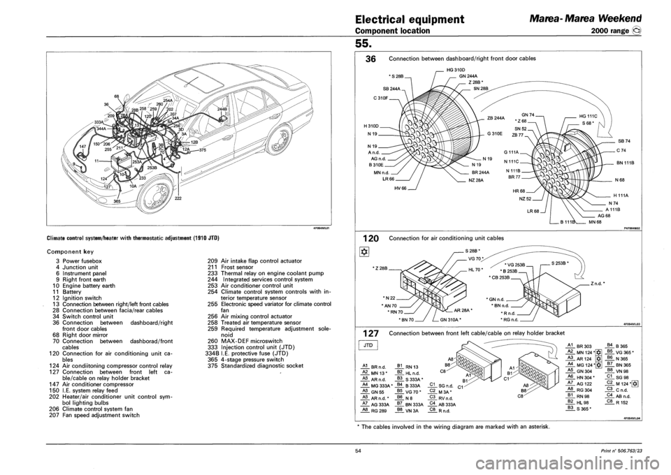
Climate control system/heater with thermostatic adjustment (1910 JTO)
Component key
Power fusebox
Junction unit
Instrument panel
Right front earth
Engine battery earth
Battery
Ignition switch
Connection between right/left front cables
Connection between facia/rear cables
Switch control unit
Connection between
front door cables
Right door mirror
Connection between
cables
Connection for air conditioning unit ca
bles
124 Air condiitoning compressor control relay
127 Connection between front left ca
ble/cable on relay holder bracket
Air conditioner compressor
I.E. system relay feed
Heater/air conditioner unit control sym
bol lighting bulbs
Climate control system fan
Fan speed adjustment switch
3
4
6
9
10
11
12
13
28
34
36
68
70
120
147
150
202
206
207
dashboard/right
dashborad/front
209 Air intake flap control actuator
211 Frost sensor
233 Thermal relay on engine coolant pump
244 Integrated services control system
253 Air conditioner control unit
254 Climate control system controls with in
terior temperature sensor
255 Electronic speed variator for climate control
fan
256 Air mixing control actuator
258 Treated air temperature sensor
259 Required temperature adjustment sole
noid
260 MAX-DEF microswitch
333 Injection control unit (JTD)
334B I.E. protective fuse (JTD)
365 4-stage pressure switch
375 Standardized diagnostic socket
55.
36 Connection between dashboard/right front door cables
' S 28B.
HG310D
GN 244A
Z28B*
SN 28B
A n.d.
AG n.d.
B310E
MN n.d
LR66
BN 111B
HV66
1 20 Connection for air conditioning unit cables
' Z 28B
*N22.
"AN 70
.Zn.d.
1 27 Connection between front left cable/cable on relay holder bracket
JTD
HL BR n.d.
_ALMNI3*
HL AR n.d.
HL MG 333A'
HL GN55
HL AR n.d. *
HL AG 333A A8 RG289
_A1_ BR 303 B4 B365 A2 MN 124* $ B5 VG 365 * A3 AR124 B6 N365 A4 MG 124* $ B7 BN 365 A5 GN 304 B8 VN 98 A6 HN 304 * C1 SG 98 A7 AG 122 C2 M 124*[*g A8 RG304 C3 Cn.d. B1 RN 98 C4 AB n.d. B2 HL 98 C8 R152 B3 S365*
The cables involved in the wiring diagram are marked with an asterisk.
54 Print n° 506.763/23
Page 247 of 330
Marea-Marea Weekend
2000 range ©
Electrical equipment
Wiring diagrams
55.
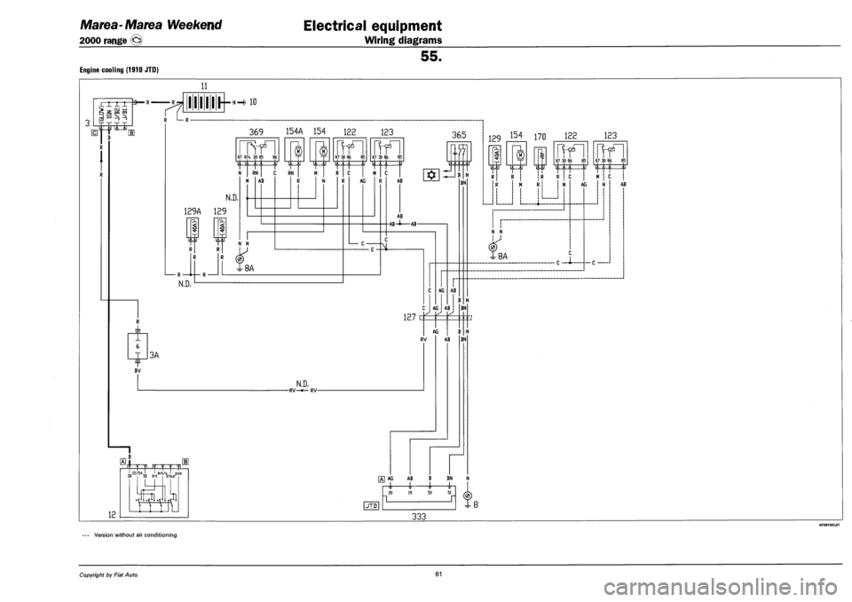
Engine cooling (1910 JTD)
11
XXXX *
3 I_S
> -, OJ ° § s?
T. |i it TJ
BV
7?
I 11 I I I—»-H ' 10
R L— R •
369 154A 154 122 123
N RN RN
N.D.
129A 129
o
N.D.
AB
N N
®
X8A
?
<
J i
3A
12
frr f T Y v Ll
87 87a 30 85 86 f T 87 30 86 85 <" ™ °c °'
HIT f
N,D, -RV-*- RV-
87 30 86 85
li
M C
365
AG AB
7i
AB
AB--AB-
127 C
AG
AG
AB
! B
BN
AB
AG
RV
BN
B
AB BN
N
[Al AG AB B BN N
i 4- i 1 1
(JTD]
SO 19 52 51
129 154 170 122 123
87 30 86 85
i I i
R ! c
I i I
87 30 86 85
. ifu to i iii i
M ! c !
N N i i I
(0)
8A
333
AG
C —A-—-»— C —
N AB
Version without air conditioning
Copyright by Fiat Auto 61
Page 248 of 330
Electrical equipment
Component location
Marea-Marea Weekend
2000 range ©
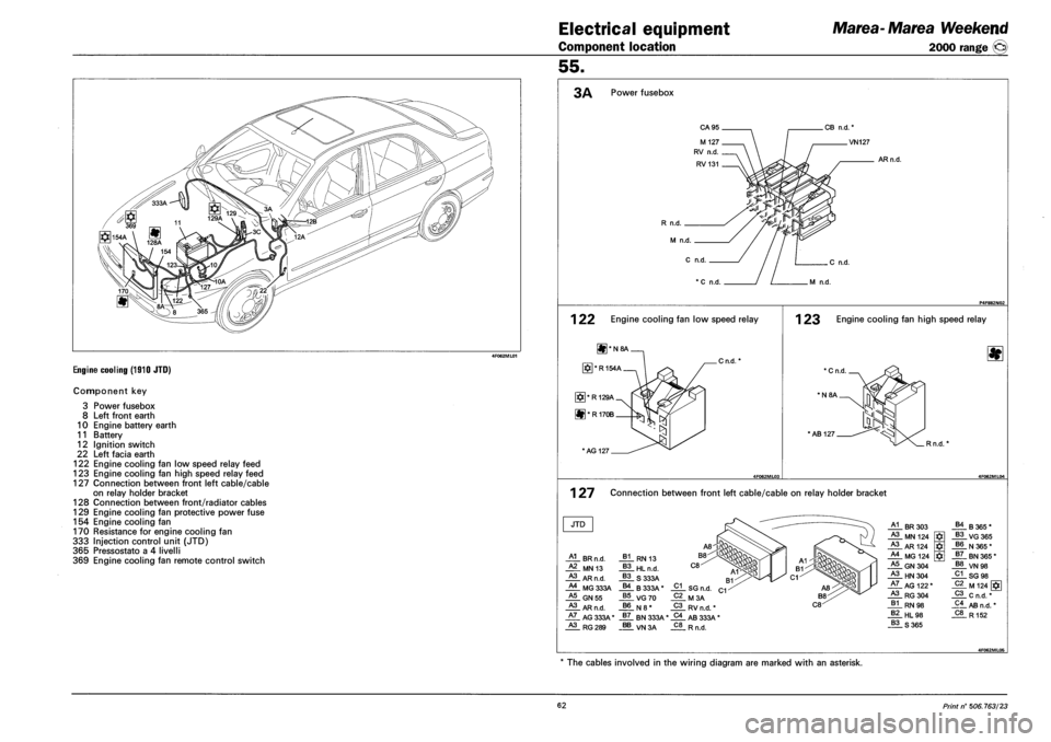
Engine cooling (1910 JTD)
Component key
3 Power fusebox
8 Left front earth
10 Engine battery earth
11 Battery
12 Ignition switch
22 Left facia earth
122 Engine cooling fan low speed relay feed
123 Engine cooling fan high speed relay feed
127 Connection between front left cable/cable
on relay holder bracket
128 Connection between front/radiator cables
129 Engine cooling fan protective power fuse
154 Engine cooling fan
170 Resistance for engine cooling fan
333 Injection control unit (JTD)
365 Pressostato a 4 livelli
369 Engine cooling fan remote control switch
55.
3A Power fusebox
CA95
R n.d.
M n.d.
AR n.d.
C n.d. .C n.d.
*C n.d M n.d.
1 22 Engine cooling fan low speed relay
U]*N8A
[#]*R154A
[§]*R129A
H*R170B h>j
* AG 127.
Cn.d.
1 23 Engine cooling fan high speed relay
'Cn.d.
' N8A.
•AB 127
. R n.d.
1 27 Connection between front left cable/cable on relay holder bracket
JTD
HL BR n.d.
HL MN 13
HL AR n.d.
HL MG 333A
_§! RN 13
_§L HLn.d.
_§L S 333A B4 B333A* A5 GN 55
HL AR n.d.
HL AG 333A'
HL RG 289
VG70 _B6_ N8.
_§7_ BN 333A'
_§§_VN3A
J2L SG n.d.
02 M3A
_2L RV n.d. *
04 AB 333A * C8 Rn.d.
HL BR 303
HL MN 124
A3 AR 1?4
HL MG 124
.AJLGN 304
HL HN 304
HL AG 122"
HL RG 304
JLL.RN98
_§£_HL98
_?LS365
_Bf_ B 365 .
_§L VG 365
_§?_ N 365 *
_§L BN 365 * B8 VN98
_2LSG 98
M 124 [§]
_2L c n.d. *
_9L AB n.d. * C8 R152
4F062MLQ5
* The cables involved in the wiring diagram are marked with an asterisk.
62 Print n° 506.763/23
Page 259 of 330
Marea-Marea Weekend
2000 range O
Electrical equipment
Wiring diagrams
55.
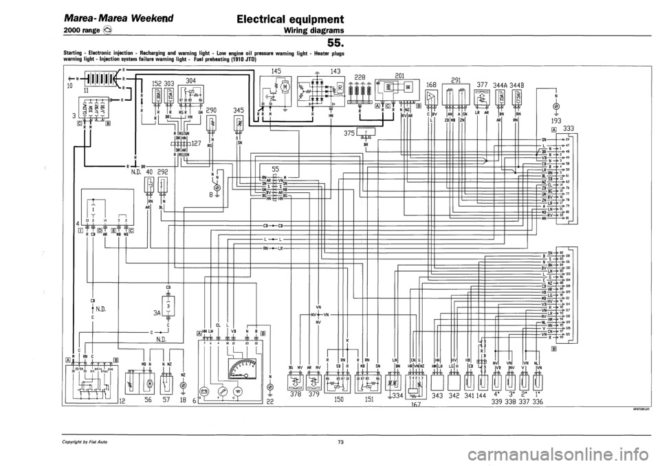
Starting - Electronic injection - Recharging and warning light - Low engine oil pressure warning light - Heater plugs
warning light - Injection system failure warning light - Fuel preheating (1910 JTD)
Copyright by Fiat Auto 73
Page 260 of 330
Electrical equipment
Component location
Marea-Marea Weekend
2000 range ©
55.
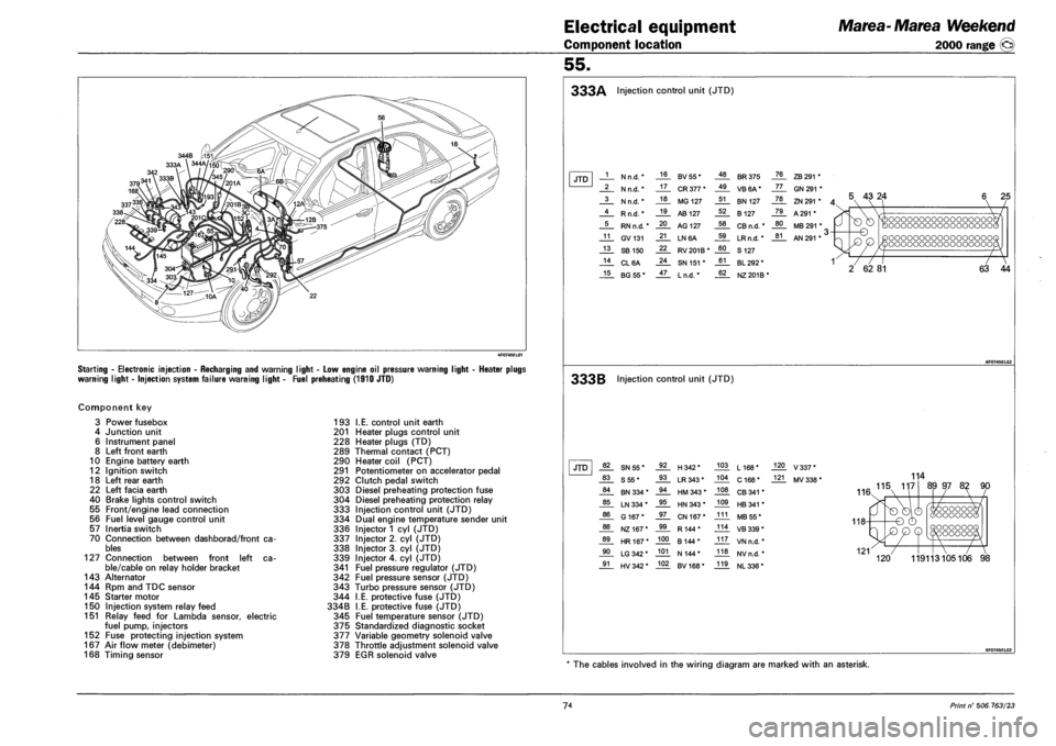
Starting - Electronic injection - Recharging and warning light - Low engine oil pressure warning
warning light - Injection system failure warning light - Fuel preheating (1910 JTD)
ight - Heater plugs
Component key
3 Power fusebox
4 Junction unit
6 Instrument panel
8 Left front earth
10 Engine battery earth
12 Ignition switch
18 Left rear earth
22 Left facia earth
40 Brake lights control switch
55 Front/engine lead connection
56 Fuel level gauge control unit
57 Inertia switch
70 Connection between dashborad/front ca
bles
127 Connection between front left ca
ble/cable on relay holder bracket
143 Alternator
144 Rpm and TDC sensor
145 Starter motor
150 Injection system relay feed
151 Relay feed for Lambda sensor, electric
fuel pump, injectors
152 Fuse protecting injection system
167 Air flow meter (debimeter)
168 Timing sensor
193 I.E. control unit earth
201 Heater plugs control unit
228 Heater plugs (TD)
289 Thermal contact (PCT)
290 Heater coil (PCT)
291 Potentiometer on accelerator pedal
292 Clutch pedal switch
303 Diesel preheating protection fuse
304 Diesel preheating protection relay
333 Injection control unit (JTD)
334 Dual engine temperature sender unit
336 Injector 1 cyl (JTD)
337 Injector 2. cyl (JTD)
338 Injector 3. cyl (JTD)
339 Injector 4. cyl (JTD)
341 Fuel pressure regulator (JTD)
342 Fuel pressure sensor (JTD)
343 Turbo pressure sensor (JTD)
344 I.E. protective fuse (JTD)
334B I.E. protective fuse (JTD)
345 Fuel temperature sensor (JTD)
375 Standardized diagnostic socket
377 Variable geometry solenoid valve
378 Throttle adjustment solenoid valve
379 EGR solenoid valve
333A Injection control unit (JTD)
JTD 1 N n.d. * 16 BV55* 48 BR 375 76 ZB 291 *
2 N n.d. * 17 CR 377 * 49 VB6A* 77 GN 291 *
3 N n.d. * 18 MG 127 51 BN 127 78 ZN 291 * A 4 Rn.d.* 19 AB 127 52 B 127 79 A 291 *
5 RN n.d. * 20 AG 127 58 CB n.d. * 80 MB 291 * ,
11 GV131 21 LN6A 59 LRn.d. * 81 AN 291 * ' >
13 SB 150 22 RV201B* 60 S 127
14 CL6A 24 SN 151 * 61 BL 292 * 1
15 BG55* 47 Ln.d. * 62 NZ 201B*
5 43 24
-o
T7
2 62 81
oooooooooooooooooc oooooooooooooooooc
oooooooooooooooooc oooooooooooooooooc
~7
63 44
333B Injection control unit (JTD)
JTD 82 SN55* 92 H342* 103 L168* 120 V337*
83 S55* 93 LR 343* 104 C 168* 121 MV 338 *
84 BN 334 * 94 HM 343 * 108 CB 341 *
85 LN 334 * 95 HN 343 * 109 HB 341 *
86 G 167* 97 CN 167* 111 MB 55*
88 NZ167* 99 R144* 114 VB 339 *
89 HR167* 100 B 144* 117 VN n.d. *
90 LG 342 * 101 N 144* 118 NVn.d. *
91 HV 342 * 102 BV168* 119 NL 336 *
114
AA 115 117
116.
89 97 82 90
oooooc OOOOOOG OOOOOOO 'OOOOOC
119113105106 98
* The cables involved in the wiring diagram are marked with an asterisk.
74 Print n° 506.763/23
Page 274 of 330
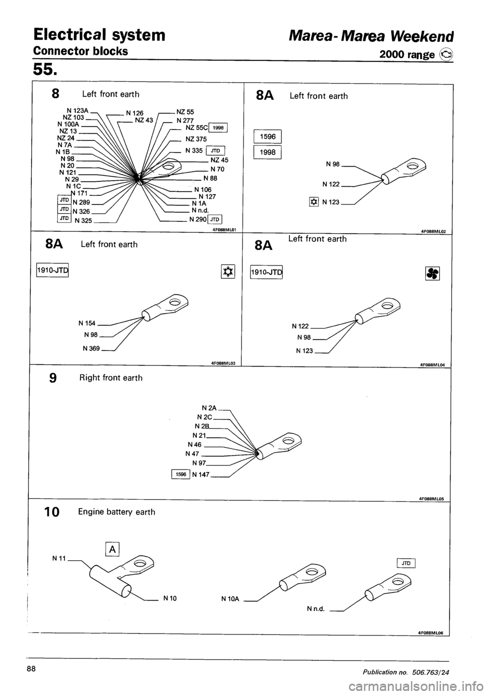
Electrical system
Connector blocks
Marea-Marea Weekend
2000 range @)
55.
8 Left front earth
N 123A. NZ103. N 100A. NZ13. NZ24. N7A. N 1B.
. N 126 NZ 55
N277
N 106 N 127 N 1A . N n.d
N290|JTD|
4F088ML01
8A Left front earth
1596
1998
N98
N 122
g*] N 123
8A Left front earth 8A Left front earth
1910-JTI 3 1910-JTD
N369
N 122
Right front earth
1596 N 147
1 0 Engine battery earth
N 11
N 10 N 10A
88 Publication no. 506.763/24
Page 292 of 330
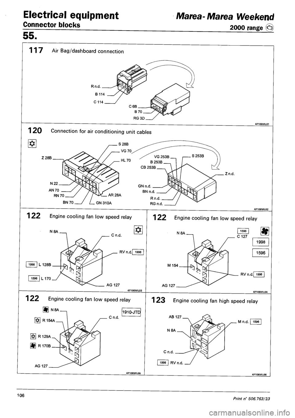
Electrical equipment
Connector blocks
Marea- Marea Weekend
2000 range ©
55.
117 Air Bag/dashboard connection
Rn.d
1 20 Connection for air conditioning unit cables
Z28B
Zn.d.
N22
AN 70
RN 70
BN 70
122 Engine cooling fan low speed relay
N8A Cn.d.
1998 L 128B
1596 L 170
RVn.d. 1998
AG 127
Cn.d.
122 Engine cooling fan low speed relay
g N8A
i§] R 154A
[§] R 129A
|#j R 170B
AG 127
1910-JTD
122 Engi ne cooling fan low speed relay
M 154
AG 127
1998
1596
RVn.d. 1998
1 23 Engine cooling fan high speed relay
AB 127
N8A
Cn.d.
1998 RVn.d
M n.d. 1596
106 Print n° 506.763/23