electrical FIAT MULTIPLA 2006 1.G User Guide
[x] Cancel search | Manufacturer: FIAT, Model Year: 2006, Model line: MULTIPLA, Model: FIAT MULTIPLA 2006 1.GPages: 266, PDF Size: 4.61 MB
Page 167 of 266
166
SAFETY
DEVICES
CORRECT USE
OF THE CAR
WARNING
LIGHTS AND
MESSAGES
CAR
MAINTENANCE
TECHNICAL
SPECIFICATIONS
INDEX
DASHBOARD
AND CONTROLS
IN AN
EMERGENCY
JUMP STARTING
If the battery is flat, it is possible to start the engine using an auxiliary
battery with the same capacity or a little higher than the flat one.
Proceed as follows:
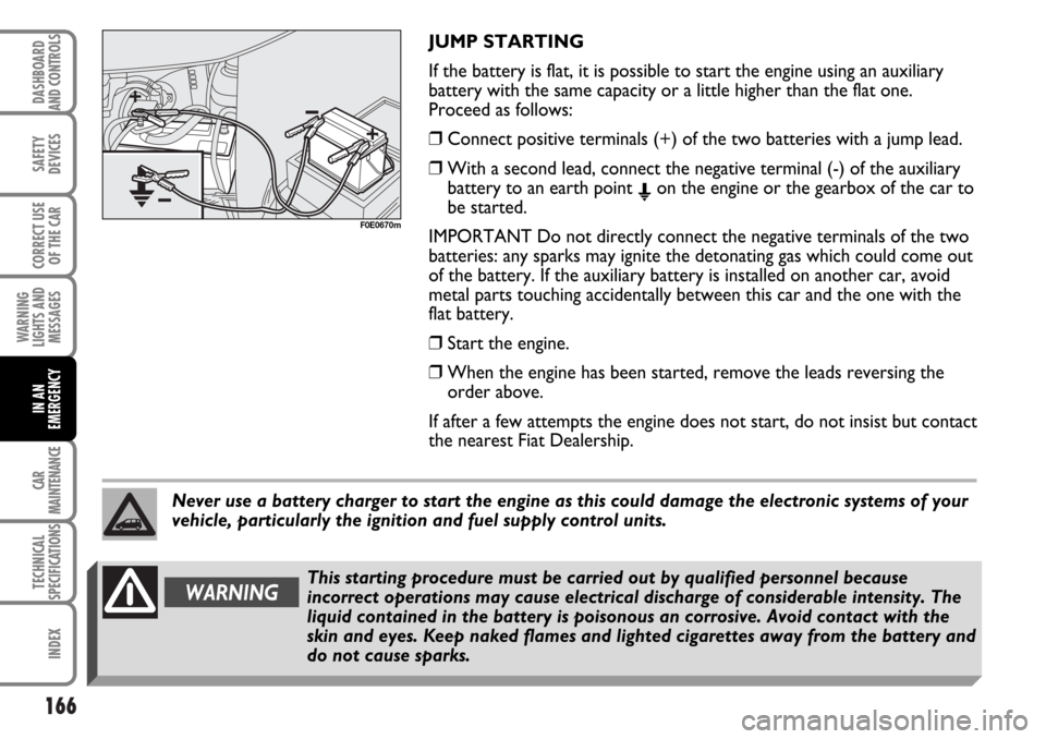
❒Connect positive terminals (+) of the two batteries with a jump lead.
❒With a second lead, connect the negative terminal (-) of the auxiliary
battery to an earth point
Eon the engine or the gearbox of the car to
be started.
IMPORTANT Do not directly connect the negative terminals of the two
batteries: any sparks may ignite the detonating gas which could come out
of the battery. If the auxiliary battery is installed on another car, avoid
metal parts touching accidentally between this car and the one with the
flat battery.
❒Start the engine.
❒When the engine has been started, remove the leads reversing the
order above.
If after a few attempts the engine does not start, do not insist but contact
the nearest Fiat Dealership.
F0E0670m
Never use a battery charger to start the engine as this could damage the electronic systems of your
vehicle, particularly the ignition and fuel supply control units.
WARNINGThis starting procedure must be carried out by qualified personnel because
incorrect operations may cause electrical discharge of considerable intensity. The
liquid contained in the battery is poisonous an corrosive. Avoid contact with the
skin and eyes. Keep naked flames and lighted cigarettes away from the battery and
do not cause sparks.
Page 168 of 266
167
SAFETY
DEVICES
CORRECT USE
OF THE CAR
WARNING
LIGHTS AND
MESSAGES
CAR
MAINTENANCE
TECHNICAL
SPECIFICATIONS
INDEX
DASHBOARD
AND CONTROLS
IN AN
EMERGENCY
BUMP STARTING
Never bump start the engine by pushing, towing or
coasting downhill.
This could cause fuel to flow into the catalytic
converter and damage it beyond repair.
IMPORTANT Remember that the servobrake and
electrical power steering system are not operating
until the engine is started, a greater effort will
therefore be required to press the brake pedal or turn
the steering wheel.IF A TYRE IS PUNCTURED
GENERAL INSTRUCTIONS
For versions/markets where applicable, the car can be
fitted with a quick tyre repair kit called FIX & GO,
replacing the usual tool fitting, the spare wheel lifting
winch and the space-saver spare wheel.
Normal spare small wheel, or (where provided)
normal size spare wheel, can be supplied on request;
for its use, follow what indicated below.
VAN versions are fitted as standard with a spare
wheel with steel rim of the same type and size as the
standard wheels mounted on the car.
Wheel changing and correct use of the jack and space-
saver spare wheel call for some precautions as listed
below.
WARNINGAlert other drivers that the car is stationary in compliance with local regulations:
hazard warning lights, warning triangle, etc. Any passengers on board should leave the
car, especially if it is heavily laden. Passengers should stay away from oncoming traffic
while the wheel is being changed. If parked on a slope or rough surface, chock the
wheels with wedges or other suitable devices to prevent the car from rolling.
Page 188 of 266
187
SAFETY
DEVICES
CORRECT USE
OF THE CAR
WARNING
LIGHTS AND
MESSAGES
CAR
MAINTENANCE
TECHNICAL
SPECIFICATIONS
INDEX
DASHBOARD
AND CONTROLS
IN AN
EMERGENCY
MAIN BEAMS
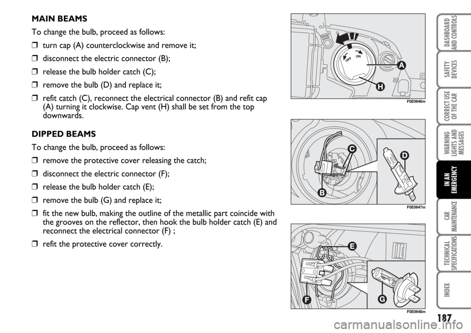
To change the bulb, proceed as follows:
❒turn cap (A) counterclockwise and remove it;
❒disconnect the electric connector (B);
❒release the bulb holder catch (C);
❒remove the bulb (D) and replace it;
❒refit catch (C), reconnect the electrical connector (B) and refit cap
(A) turning it clockwise. Cap vent (H) shall be set from the top
downwards.
DIPPED BEAMS
To change the bulb, proceed as follows:
❒remove the protective cover releasing the catch;
❒disconnect the electric connector (F);
❒release the bulb holder catch (E);
❒remove the bulb (G) and replace it;
❒fit the new bulb, making the outline of the metallic part coincide with
the grooves on the reflector, then hook the bulb holder catch (E) and
reconnect the electrical connector (F) ;
❒refit the protective cover correctly.
F0E0646m
F0E0647m
F0E0648m
Page 190 of 266
189
SAFETY
DEVICES
CORRECT USE
OF THE CAR
WARNING
LIGHTS AND
MESSAGES
CAR
MAINTENANCE
TECHNICAL
SPECIFICATIONS
INDEX
DASHBOARD
AND CONTROLS
IN AN
EMERGENCY
FRONT SIDELIGHTS
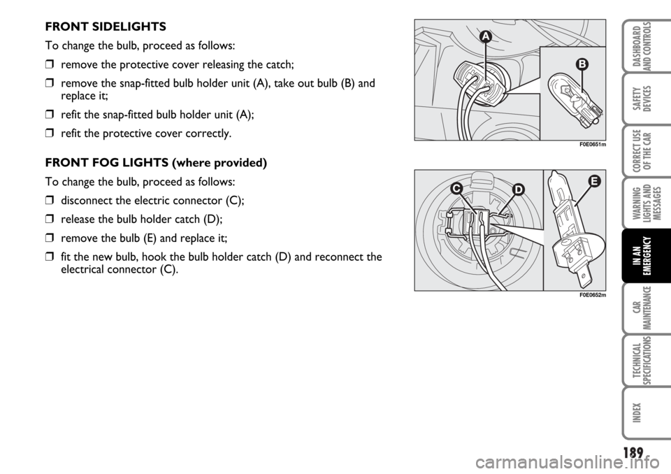
To change the bulb, proceed as follows:
❒remove the protective cover releasing the catch;
❒remove the snap-fitted bulb holder unit (A), take out bulb (B) and
replace it;
❒refit the snap-fitted bulb holder unit (A);
❒refit the protective cover correctly.
FRONT FOG LIGHTS (where provided)
To change the bulb, proceed as follows:
❒disconnect the electric connector (C);
❒release the bulb holder catch (D);
❒remove the bulb (E) and replace it;
❒fit the new bulb, hook the bulb holder catch (D) and reconnect the
electrical connector (C).
F0E0651m
F0E0652m
Page 193 of 266
192
SAFETY
DEVICES
CORRECT USE
OF THE CAR
WARNING
LIGHTS AND
MESSAGES
CAR
MAINTENANCE
TECHNICAL
SPECIFICATIONS
INDEX
DASHBOARD
AND CONTROLS
IN AN
EMERGENCY
IF AN INTERIOR LIGHT BURNS OUT
For the type of bulb and power rating, see “If a bulb burns out”.
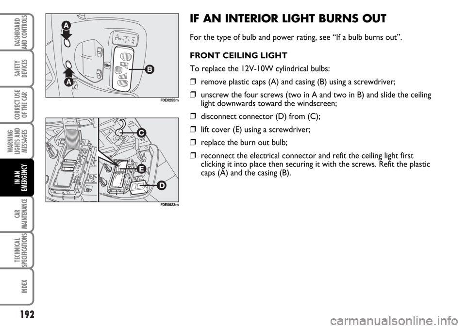
FRONT CEILING LIGHT
To replace the 12V-10W cylindrical bulbs:
❒remove plastic caps (A) and casing (B) using a screwdriver;
❒unscrew the four screws (two in A and two in B) and slide the ceiling
light downwards toward the windscreen;
❒disconnect connector (D) from (C);
❒lift cover (E) using a screwdriver;
❒replace the burn out bulb;
❒reconnect the electrical connector and refit the ceiling light first
clicking it into place then securing it with the screws. Refit the plastic
caps (A) and the casing (B).
F0E0255m
F0E0623m
Page 196 of 266
195
SAFETY
DEVICES
CORRECT USE
OF THE CAR
WARNING
LIGHTS AND
MESSAGES
CAR
MAINTENANCE
TECHNICAL
SPECIFICATIONS
INDEX
DASHBOARD
AND CONTROLS
IN AN
EMERGENCY
Certain fuses are protected by a plastic grid.
To replace these fuses, first of all remove the grid
using a screwdriver. Replace the blown fuse and refit
the plastic grid.
To locate the fuse, refer to the tables on the following
pages.
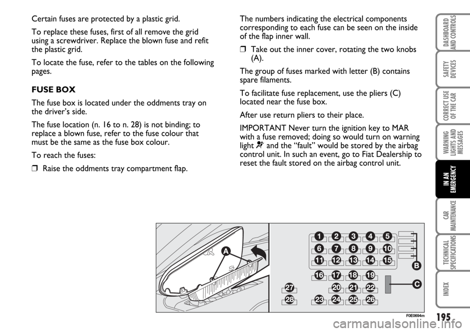
FUSE BOX
The fuse box is located under the oddments tray on
the driver’s side.
The fuse location (n. 16 to n. 28) is not binding; to
replace a blown fuse, refer to the fuse colour that
must be the same as the fuse box colour.
To reach the fuses:
❒Raise the oddments tray compartment flap.
F0E0694m
The numbers indicating the electrical components
corresponding to each fuse can be seen on the inside
of the flap inner wall.
❒Take out the inner cover, rotating the two knobs
(A).
The group of fuses marked with letter (B) contains
spare filaments.
To facilitate fuse replacement, use the pliers (C)
located near the fuse box.
After use return pliers to their place.
IMPORTANT Never turn the ignition key to MAR
with a fuse removed; doing so would turn on warning
light
¬and the “fault” would be stored by the airbag
control unit. In such an event, go to Fiat Dealership to
reset the fault stored on the airbag control unit.
Page 197 of 266
196
SAFETY
DEVICES
CORRECT USE
OF THE CAR
WARNING
LIGHTS AND
MESSAGES
CAR
MAINTENANCE
TECHNICAL
SPECIFICATIONS
INDEX
DASHBOARD
AND CONTROLS
IN AN
EMERGENCY
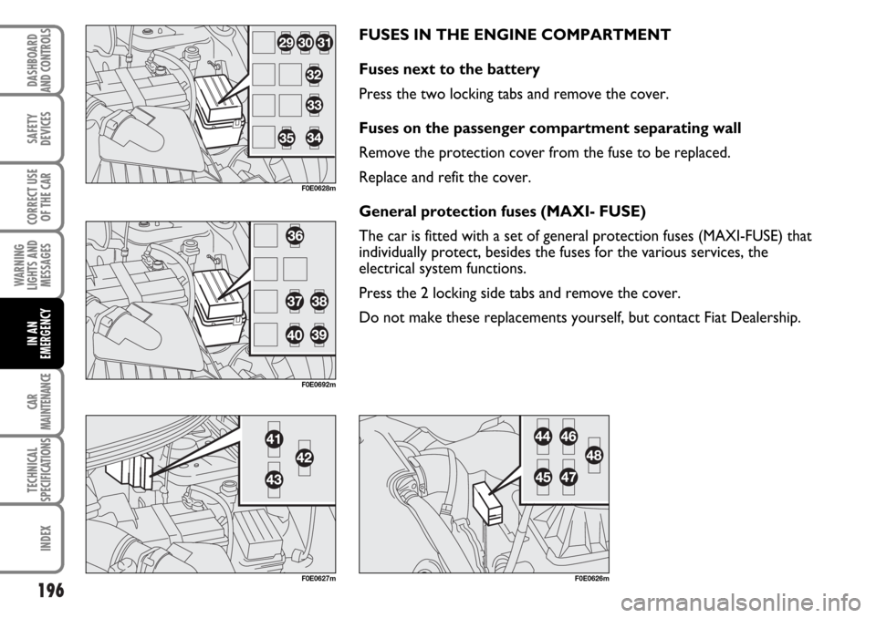
FUSES IN THE ENGINE COMPARTMENT
Fuses next to the battery
Press the two locking tabs and remove the cover.
Fuses on the passenger compartment separating wall
Remove the protection cover from the fuse to be replaced.
Replace and refit the cover.
General protection fuses (MAXI- FUSE)
The car is fitted with a set of general protection fuses (MAXI-FUSE) that
individually protect, besides the fuses for the various services, the
electrical system functions.
Press the 2 locking side tabs and remove the cover.
Do not make these replacements yourself, but contact Fiat Dealership.
F0E0626mF0E0627m
F0E0628m
F0E0692m
Page 223 of 266
222
SAFETY
DEVICES
CORRECT USE
OF THE CAR
WARNING
LIGHTS AND
MESSAGES
IN AN
EMERGENCY
TECHNICAL
SPECIFICATIONS
INDEX
DASHBOARD
AND CONTROLS
CAR
MAINTENANCE
Incorrect fitting of electrical and electronic accessories can seriously damage the car. If after buying
the car, you want to install electric accessories which require permanent electric supply (alarm,
sound system, free-hand phone kit, etc.) contact Fiat Dealership whose qualified personnel, in
addition to suggesting the most suitable devices, will evaluate the overall electric absorption,
checking whether the car’s electric system is capable of withstanding the load required, or whether
it should be integrated with a more powerful battery.
WARNINGWhen working on the battery or near it, always wear the proper goggles.
WARNINGRunning the battery with low fluid level can damage the battery beyond repair and
could also cause its explosion. CHANGING THE BATTERY
If required, replace the battery with a genuine spare
part having the same specifications. If a battery with
different specifications is fitted, the service intervals
given in the “Service Schedule” in this section will nolonger be valid. Refer to the instructions provided by
the battery’s Manufacturer.
WARNINGIf the car is left inactive for long periods at cold, remove the battery and store it in
a warm place to prevent freezing.
Page 224 of 266
223
SAFETY
DEVICES
CORRECT USE
OF THE CAR
WARNING
LIGHTS AND
MESSAGES
TECHNICAL
SPECIFICATIONS
INDEX
DASHBOARD
AND CONTROLS
IN AN
EMERGENCY
CAR
MAINTENANCE
USEFUL ADVICE FOR LENGTHENING
THE LIFE OF YOUR BATTERY
To avoid draining your battery and lengthen its life,
observe the following indications:
❒when you park the car, ensure the doors, tailgate
and bonnet are closed properly. Passenger’s
compartment lights must be off;
❒ceiling lights must be off. The car is however
provided with an automatic system for switching off
internal lights;
❒do not keep accessories (e.g.: sound system, hazard
lights, etc.) switched on for a long time when the
engine is not running;
❒before performing any operation on the electrical
system, disconnect the battery negative cable;
❒battery terminals shall always be perfectly tightened.
IMPORTANT A battery which is kept at a charge of
less than 50% (optical indicator with dark colour
without green area in the middle) for any length of
time will be damaged by sulphation leading to a
reduction in cranking power.Moreover, this might lead to a higher risk of the
battery electrolyte freezing (this may even occur at -
10°C). If the car is inactive for a long period of time,
refer to “Storing the car”, in section “Driving your
car”.
If after buying the car, you want to install electric
accessories which require permanent electric supply
(alarm, etc.) contact Fiat Dealership whose qualified
personnel, in addition to suggesting the most suitable
devices, will evaluate the overall electric absorption,
checking whether the car’s electric system is capable
of withstanding the load required, or whether it
should be integrated with a more powerful battery.
In fact, since these devices continue absorbing energy
even when the ignition key is off, they gradually run
down the battery.
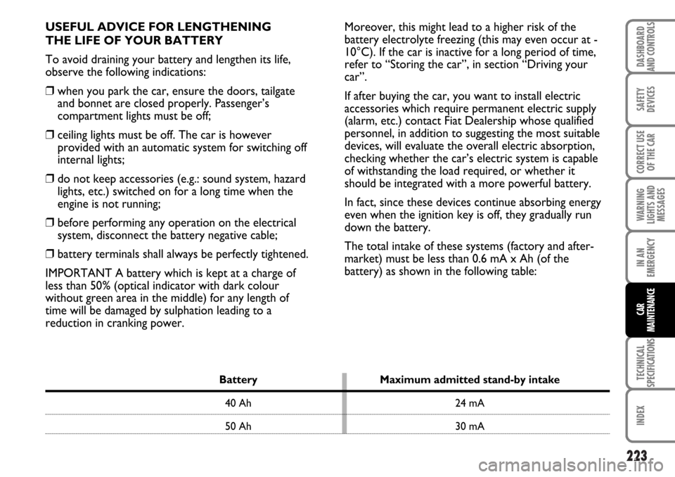
The total intake of these systems (factory and after-
market) must be less than 0.6 mA x Ah (of the
battery) as shown in the following table:
Battery Maximum admitted stand-by intake
40 Ah 24 mA
50 Ah 30 mA
Page 258 of 266
TECHNICAL
SPECIFICATIONS
257
SAFETY
DEVICES
CORRECT USE
OF THE CAR
WARNING
LIGHTS AND
MESSAGES
CAR
MAINTENANCE
INDEX
DASHBOARD
AND CONTROLS
IN AN
EMERGENCY
– hazard lights................................ 65
– heated rear window ................. 65
– rear fog lights ............................. 65
Consumption
– engine oil ..................................... 215
– fuel ................................................ 252
Current sockets .............................. 70
Dashboard ....................................... 5
Demisting/defrosting................ 51-53-55
– rear window ............................... 51-53
– windscreen and windows ..... 51-53
Diesel fuel filter ............................... 221
Differential ........................................ 238
Dimensions ....................................... 244
Dipped beam headlights
– bulb replacement ...................... 187
– control ......................................... 59
Direction indicators
– control ......................................... 60
– front bulb replacement ............ 188
– rear bulb replacement ............. 190
– side bulb replacement .............. 188
Doors
– child safety device ..................... 75
– opening/closing .......................... 74
Fiat Code (system) ........................ 8
FIX & GO automatic
(quick tyre repair kit) .................. 175
Fluids and lubricants ....................... 250
Front fog lights ................................. 65
– bulb replacement ..................... 187
– control ......................................... 65
Fuel
– consumption ............................. 252
– fuel cut-off switch .................... 66
– gauge ........................................... 18
Fuel filler cap .................................... 108
Fuses replacement .......................... 194
Gearbox
– type............................................... 238
– use ............................................... 142
Glove compartments/oddment trays
– driver's side ................................ 67
– passenger's side ........................ 67
– under seat .................................. 68
– under sun visors ........................ 68
Handbrake ....................................... 141
Hazard lights .................................... 65
Headlights.......................................... 88
– adjusting the headlight beam .. 88
Electric windows ............................ 76
– front ............................................. 76
– rear ............................................... 77
Electrically controlled sunroof ..... 72
– controls ....................................... 73
– roof closure safety system ...... 72
Electronic alarm............................... 11
– deactivation ................................ 13
– operation .................................... 11
– programming .............................. 12
– self-test ........................................ 12
– when alarm is triggered ........... 14
Engine
– identification code..................... 236
– marking ........................................ 235
– technical data ............................. 237
Engine codes ..................................... 236
Engine coolant level ........................ 216
Engine compartment (washing) .... 231
Engine oil
– checking level ............................. 214
– consumption............................... 215
– specifications .............................. 249
EOBD system ................................... 96
ESP (system) ..................................... 92