tow FIAT MULTIPLA 2006 1.G User Guide
[x] Cancel search | Manufacturer: FIAT, Model Year: 2006, Model line: MULTIPLA, Model: FIAT MULTIPLA 2006 1.GPages: 266, PDF Size: 4.61 MB
Page 144 of 266
143
WARNING
LIGHTS AND
MESSAGES
IN AN
EMERGENCY
CAR
MAINTENANCE
TECHNICAL
SPECIFICATIONS
INDEX
DASHBOARD
AND CONTROLS
SAFETY
DEVICES
CORRECT USE
OF THE CAR
CONTAINING RUNNING COSTS
Here are some suggestions which may help you to
keep the running costs of your car down and lower
the amount of toxic emissions released into the
atmosphere.
GENERAL CONSIDERATIONS
Car maintenance
Have checks and adjustments carried out in
accordance with the “Service schedule”.
Tyres
Check the pressure of the tyres routinely at an
interval of no more than 4 weeks: if the pressure is
too low, consumption levels increase as resistance to
rolling is higher.
Unnecessary loads
Do not travel with too much luggage stowed in the
boot. The weight of the car (especially when driving in
town) and its trim greatly affects consumption and
stability.Roof rack/ski rack
Remove the roof rack or the ski rack from the roof as
soon as they are no longer used. These accessories
lower air penetration and adversely affect
consumption levels. When needing to carry
particularly voluminous objects, preferably use a
trailer.
Electric devices
Use electric devices only for the amount of time
needed. Rear heated window, additional headlights,
windscreen wipers and heater fan need a considerable
amount of energy, therefore increasing the
requirement of current increases fuel consumption (up
to +25% in the urban cycle).
Climate control
The air conditioner is an additional load which greatly
affects the engine leading to higher consumption (on
average up to +20%). When the temperature outside
the vehicle permits it, use the air vents where possible.
Aerodynamic accessories
The use of non-certified aerodynamic items may
adversely affect air drag and consumption levels.
Page 146 of 266
145
WARNING
LIGHTS AND
MESSAGES
IN AN
EMERGENCY
CAR
MAINTENANCE
TECHNICAL
SPECIFICATIONS
INDEX
DASHBOARD
AND CONTROLS
SAFETY
DEVICES
CORRECT USE
OF THE CAR
TOWING TRAILERS
IMPORTANT NOTES
For towing caravans or trailers the car must be fitted
with a certified tow hook and an adequate electric
system. Installation should be carried out by
specialised personnel who release a special document
for circulation on the road.
Install any specific and/or additional rear-view mirrors
in accordance with the Highway Code.
Remember that when towing a trailer, steep hills are
harder to climb, the braking spaces increase and
overtaking takes longer depending on the overall
weight.Engage a low gear when driving downhill, rather than
constantly using the brake.
The weight the trailer exerts on the car tow hook
reduces by the same amount the actual vehicle loading
capacity.
To make sure the maximum towable weight is not
exceeded, account should be taken of the fully laden
trailer, including accessories and personal belongings.
Do not exceed the speed limits of the country you are
driving in. In any case do not exceed 100 km/h.
WARNINGThe ABS system with which the car may be fitted does not control the trailer
braking system.
Under no circumstances should the vehicle brake system be altered to control the
trailer brake. The trailer braking system must be fully independent of the vehicle’s
hydraulic system.WARNING
Page 147 of 266
146
WARNING
LIGHTS AND
MESSAGES
IN AN
EMERGENCY
CAR
MAINTENANCE
TECHNICAL
SPECIFICATIONS
INDEX
DASHBOARD
AND CONTROLS
SAFETY
DEVICES
CORRECT USE
OF THE CAR
INSTALLING THE TOW HOOK
The towing device should be fastened to the body by
specialised personnel according to any additional
and/or integrative information supplied by the
Manufacturer of the device.
Have installation carried out at Fiat Dealership.
The towing device must meet current regulations with
reference to 94/20/EC Directive and subsequent
amendments.
For any version the towing device used must match
the towable weight of the car on which it is to be
installed.
For the electric connection a unified connector should
be used which is generally placed on a special bracket
normally fastened to the towing device, and a special
ECU for external trailer light control shall be installed
on the car.
When fitting the trailer, parking sensors are
deactivated.For the electrical connection, a 7 pin 12VDC
connection is to be used (CUNA/UNI and ISO/DIN
Standards). Follow the instructions provided by the car
manufacturer and/or the tow hitch manufacturer.
An electric brake should be supplied directly by the
battery through a cable with a cross section of no less
than 2.5 mm
2.
IMPORTANT Electric brake or other device shall be
used with running engine.
In addition to the electrical branches, the car’s electric
system can only be connected to the supply cable for
an electric brake and to the cable for an internal light,
though not above 15W.
For connections, use the preset control unit with
battery cable no less than 2.5 mm
2.
The two hitches are shown on the following pages.
Page 148 of 266
147
WARNING
LIGHTS AND
MESSAGES
IN AN
EMERGENCY
CAR
MAINTENANCE
TECHNICAL
SPECIFICATIONS
INDEX
DASHBOARD
AND CONTROLS
SAFETY
DEVICES
CORRECT USE
OF THE CAR
F0E0192m
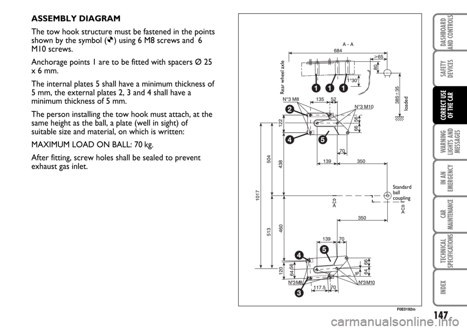
ASSEMBLY DIAGRAM
The tow hook structure must be fastened in the points
shown by the symbol (
Ø) using 6 M8 screws and 6
M10 screws.
Anchorage points 1 are to be fitted with spacers Ø 25
x 6 mm.
The internal plates 5 shall have a minimum thickness of
5 mm, the external plates 2, 3 and 4 shall have a
minimum thickness of 5 mm.
The person installing the tow hook must attach, at the
same height as the ball, a plate (well in sight) of
suitable size and material, on which is written:
MAXIMUM LOAD ON BALL: 70 kg.
After fitting, screw holes shall be sealed to prevent
exhaust gas inlet.
Rear wheel axle
loaded
Standard
ball
coupling
Page 149 of 266
148
WARNING
LIGHTS AND
MESSAGES
IN AN
EMERGENCY
CAR
MAINTENANCE
TECHNICAL
SPECIFICATIONS
INDEX
DASHBOARD
AND CONTROLS
SAFETY
DEVICES
CORRECT USE
OF THE CAR
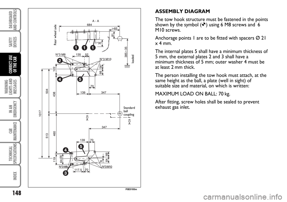
ASSEMBLY DIAGRAM
The tow hook structure must be fastened in the points
shown by the symbol (
Ø) using 6 M8 screws and 6
M10 screws.
Anchorage points 1 are to be fitted with spacers Ø 21
x 4 mm.
The internal plates 5 shall have a minimum thickness of
5 mm, the external plates 2 and 3 shall have a
minimum thickness of 5 mm; outer washer 4 must be
at least 2 mm thick.
The person installing the tow hook must attach, at the
same height as the ball, a plate (well in sight) of
suitable size and material, on which is written:
MAXIMUM LOAD ON BALL: 70 kg.
After fitting, screw holes shall be sealed to prevent
exhaust gas inlet.
F0E0193m
Rear wheel axle
loaded
Standard
ball
coupling
Page 165 of 266
164
SAFETY
DEVICES
CORRECT USE
OF THE CAR
WARNING
LIGHTS AND
MESSAGES
CAR
MAINTENANCE
TECHNICAL
SPECIFICATIONS
INDEX
DASHBOARD
AND CONTROLS
IN AN
EMERGENCY
I I
N N
A A
N N
E E
M M
E E
R R
G G
E E
N N
C C
Y Y
ENGINE STARTING .................................................. 165
IF A TYRE IS PUNCTURED ..................................... 167
QUICK TYRE REPAIR KIT
FIX & GO AUTOMATIC .......................................... 177
IF A BULB BURNS OUT ........................................... 183
IF AN EXTERIOR LIGHT BURNS OUT ............... 186
IF AN INTERIOR LIGHT BURNS OUT ............... 192
IF A FUSE BLOWS ..................................................... 194
IF THE BATTERY IS FLAT ........................................ 202
JACKING THE CAR .................................................. 203
TOWING THE CAR ................................................. 203
Page 168 of 266
167
SAFETY
DEVICES
CORRECT USE
OF THE CAR
WARNING
LIGHTS AND
MESSAGES
CAR
MAINTENANCE
TECHNICAL
SPECIFICATIONS
INDEX
DASHBOARD
AND CONTROLS
IN AN
EMERGENCY
BUMP STARTING
Never bump start the engine by pushing, towing or
coasting downhill.
This could cause fuel to flow into the catalytic
converter and damage it beyond repair.
IMPORTANT Remember that the servobrake and
electrical power steering system are not operating
until the engine is started, a greater effort will
therefore be required to press the brake pedal or turn
the steering wheel.IF A TYRE IS PUNCTURED
GENERAL INSTRUCTIONS
For versions/markets where applicable, the car can be
fitted with a quick tyre repair kit called FIX & GO,
replacing the usual tool fitting, the spare wheel lifting
winch and the space-saver spare wheel.
Normal spare small wheel, or (where provided)
normal size spare wheel, can be supplied on request;
for its use, follow what indicated below.
VAN versions are fitted as standard with a spare
wheel with steel rim of the same type and size as the
standard wheels mounted on the car.
Wheel changing and correct use of the jack and space-
saver spare wheel call for some precautions as listed
below.
WARNINGAlert other drivers that the car is stationary in compliance with local regulations:
hazard warning lights, warning triangle, etc. Any passengers on board should leave the
car, especially if it is heavily laden. Passengers should stay away from oncoming traffic
while the wheel is being changed. If parked on a slope or rough surface, chock the
wheels with wedges or other suitable devices to prevent the car from rolling.
Page 178 of 266
177
SAFETY
DEVICES
CORRECT USE
OF THE CAR
WARNING
LIGHTS AND
MESSAGES
CAR
MAINTENANCE
TECHNICAL
SPECIFICATIONS
INDEX
DASHBOARD
AND CONTROLS
IN AN
EMERGENCY
QUICK TYRE REPAIR KIT
FIX & GO automatic
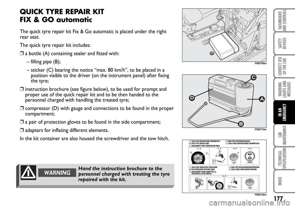
The quick tyre repair kit Fix & Go automatic is placed under the right
rear seat.
The quick tyre repair kit includes:
❒a bottle (A) containing sealer and fitted with:
– filling pipe (B);
– sticker (C) bearing the notice “max. 80 km/h”, to be placed in a
position visible to the driver (on the instrument panel) after fixing
the tyre;
❒instruction brochure (see figure below), to be used for prompt and
proper use of the quick repair kit and to be then handed to the
personnel charged with handling the treated tyre;
❒compressor (D) with gauge and connections to be found in the proper
compartment;
❒a pair of protection gloves to be found in the side compartment;
❒adapters for inflating different elements.
In the kit container are also housed the screwdriver and the tow hitch.
F0E0709m
F0E0710m
F0E0722m
Hand the instruction brochure to the
personnel charged with treating the tyre
repaired with the kit.WARNING
Page 193 of 266
192
SAFETY
DEVICES
CORRECT USE
OF THE CAR
WARNING
LIGHTS AND
MESSAGES
CAR
MAINTENANCE
TECHNICAL
SPECIFICATIONS
INDEX
DASHBOARD
AND CONTROLS
IN AN
EMERGENCY
IF AN INTERIOR LIGHT BURNS OUT
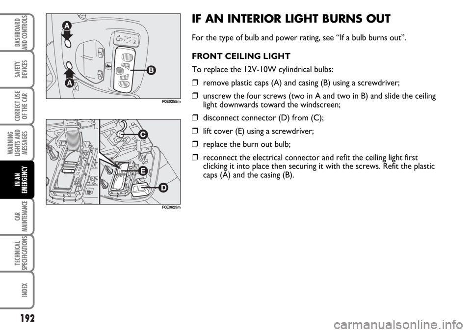
For the type of bulb and power rating, see “If a bulb burns out”.
FRONT CEILING LIGHT
To replace the 12V-10W cylindrical bulbs:
❒remove plastic caps (A) and casing (B) using a screwdriver;
❒unscrew the four screws (two in A and two in B) and slide the ceiling
light downwards toward the windscreen;
❒disconnect connector (D) from (C);
❒lift cover (E) using a screwdriver;
❒replace the burn out bulb;
❒reconnect the electrical connector and refit the ceiling light first
clicking it into place then securing it with the screws. Refit the plastic
caps (A) and the casing (B).
F0E0255m
F0E0623m
Page 204 of 266
203
SAFETY
DEVICES
CORRECT USE
OF THE CAR
WARNING
LIGHTS AND
MESSAGES
CAR
MAINTENANCE
TECHNICAL
SPECIFICATIONS
INDEX
DASHBOARD
AND CONTROLS
IN AN
EMERGENCY
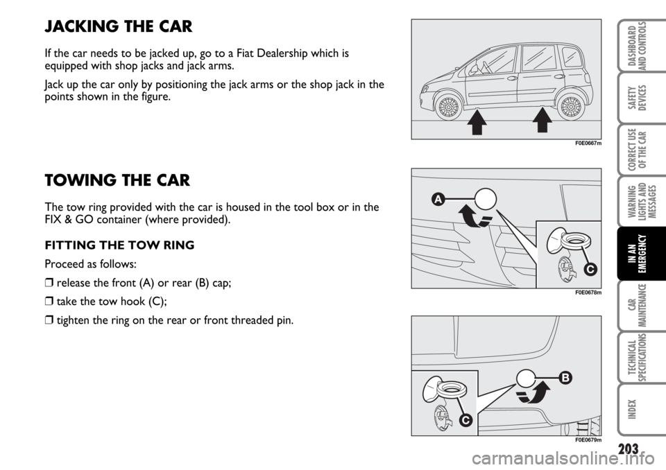
JACKING THE CAR
If the car needs to be jacked up, go to a Fiat Dealership which is
equipped with shop jacks and jack arms.
Jack up the car only by positioning the jack arms or the shop jack in the
points shown in the figure.
TOWING THE CAR
The tow ring provided with the car is housed in the tool box or in the
FIX & GO container (where provided).
FITTING THE TOW RING
Proceed as follows:
❒release the front (A) or rear (B) cap;
❒take the tow hook (C);
❒tighten the ring on the rear or front threaded pin.
F0E0667m
F0E0678m
F0E0679m