engine FIAT PANDA 2014 319 / 3.G Workshop Manual
[x] Cancel search | Manufacturer: FIAT, Model Year: 2014, Model line: PANDA, Model: FIAT PANDA 2014 319 / 3.GPages: 284, PDF Size: 11.54 MB
Page 145 of 284
The
warning light switches on when water is
detected in the diesel filter.
A specific message is displayed on certain versions.If the warning light
switches on (on
some versions the warning light
is
accompanied by the dedicated message
on the display), contact a Fiat Dealership as soon
as possible to have the system bled. If the above
indication occurs immediately after refuelling,
water may have entered the tank: stop the engine
immediately and contact a Fiat Dealership.
REAR FOG LIGHT (amber)
The warning light switches on when the rear fog
lights are activated.FOG LIGHTS (green)
The warning light switches on when the fog lights are
activated.
SIDE LIGHTS AND DIPPED
HEADLIGHTS (green)/FOLLOW ME
HOME (green)
SIDE LIGHTS AND DIPPED HEADLIGHTS
The warning light switches on when side lights
or dipped headlights are activated.
FOLLOW ME HOME
This warning light switches on (on some versions
together with a message and a symbol in the display)
when this device is used (see the "Follow me home"
paragraph in the "Knowing your car" section).MAIN BEAM HEADLIGHTS (blue)
The warning light switches on when the main beam
headlights are activated.LEFT DIRECTION INDICATOR
(green) (intermittent)
The warning light switches on when the direction
indicator control stalk is moved downwards or,
together with the right indicator, when the hazard
warning light button is pressed.
141GETTING TO KNOW
YOUR CAR
SAFETY
STARTING AND
DRIVINGWARNING LIGHTS
AND MESSAGESIN AN EMERGENCY
SERVICING AND
MAINTENANCE
TECHNICAL
SPECIFICATIONS
INDEX
Page 147 of 284
IN AN EMERGENCY
In an emergency we recommend that you call the free-phone number found on the Warranty
Booklet.You can also go to the www.fiat.com website to find your nearest Fiat Dealership.STARTING THE ENGINEContact to a Fiat Dealership immediately if
instrument panel warning light
comes on
constantly.
JUMP STARTING
If the battery is flat, the engine may be started using
an auxiliary battery with the same capacity or a
little higher than the flat one.
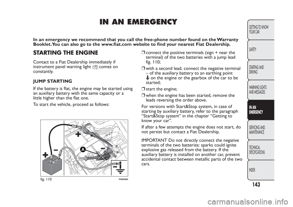
To start the vehicle, proceed as follows:❒connect the positive terminals (sign + near the
terminal) of the two batteries with a jump lead
fig. 110;
❒with a second lead, connect the negative terminal
– of the auxiliary battery to an earthing point
on the engine or the gearbox of the car to be
started;
❒start the engine;
❒when the engine has been started, remove the
leads reversing the order above.
For versions with Start&Stop system, in case of
starting by auxiliary battery, refer to the paragraph
“Start&Stop system” in the chapter “Getting to
know your car”.
If after a few attempts the engine does not start, do
not persist but contact a Fiat Dealership.
IMPORTANT Do not directly connect the negative
terminals of the two batteries: sparks could ignite
explosive gas released from the battery. If the
auxiliary battery is installed on another car, prevent
accidental contact between metallic parts of the two
cars.
fig. 110
F0W0084
143GETTING TO KNOW
YOUR CAR
SAFETY
STARTING AND
DRIVING
WARNING LIGHTS
AND MESSAGESIN AN
EMERGENCYSERVICING AND
MAINTENANCE
TECHNICAL
SPECIFICATIONS
INDEX
Page 148 of 284
Never use a fast batter y-charger to star t
the engine as this could damage the
electronic systems of your car, par ticularly
the ignition and fuel supply control units.
WARNING
This procedure must be performed by
exper t personnel because incorrect
actions could cause electrical discharge of
considerable intensity. Furthermore, battery
fluid is poisonous and corrosive: avoid contact
with skin and eyes. Keep naked flames and
lighted cigarettes away from the battery and do
not cause sparks.
BUMP STARTING
Never bump start the engine by pushing, towing or
coasting downhill.
IMPORTANT Remember that the brake servo and
electrical power steering system are not active until
the engine is started. A much greater effort will
therefore be required to use the brake pedal or turn
the steering wheel.
CHANGING A WHEELGENERAL INSTRUCTIONS
The car is equipped with the “FIX&GO Automatic
Kit”: see the paragraph “FIX&GO Automatic Kit” for
how to use this device. As an alternative to the
“FIX&GO Automatic Kit” the car may be equipped
with a space-saver wheel: see the instructions on the
following pages for changing the tyre.
WARNING
The space-saver wheel (for versions/
markets where provided) is specific to
your car, do not use it on other models, or use
the space-saver wheel of other models on your
car.The space-saver wheel must only be used
in case of emergency. It must only be used
for the distance necessary to reach a service
point and the car speed must not exceed 80
km/h.The space-saver wheel has an orange
sticker that summarises the main cautions for
use and limitations. Never remove or cover
the label.The following information is provided
in four languages on the label: "Important!
For temporar y use only! 80 km/h max! Replace
with a standard tire as soon as possible. Never
cover this indication." Never apply a wheel
cap on a space-saver wheel.
144
GETTING TO KNOW
YOUR CAR
SAFETY
STARTING AND
DRIVING
WARNING LIGHTS
AND MESSAGES
IN AN
EMERGENCY
SERVICING AND
MAINTENANCE
TECHNICAL
SPECIFICATIONS
INDEX
Page 150 of 284
JACK
Important notes:
❒the jack weight is 1.76 kg;
❒the jack requires no adjustment;
❒the jack cannot be repaired and in the event of a
fault it must be replaced by another original one;
❒no tool other than its cranking device may be
fitted on the jack.
To change a wheel proceed as follows:
❒stop the car in a position that is not dangerous for
oncoming traffic where you can change the wheel
safely. The ground must be flat and sufficiently
compact;
❒switch off the engine, pull up the handbrake and
engage the 1
st
gear or the reverse gear. Wear the
reflective safety jacket (compulsory by law in
certain countries) before getting out of the car;
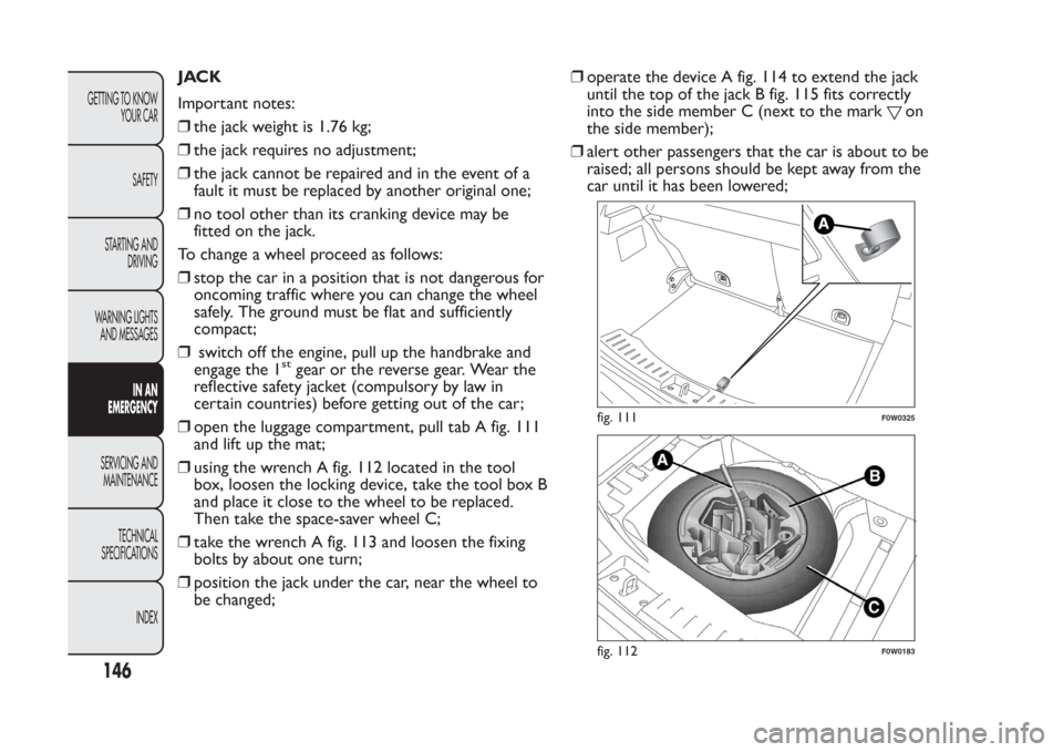
❒open the luggage compartment, pull tab A fig. 111
and lift up the mat;
❒using the wrench A fig. 112 located in the tool
box, loosen the locking device, take the tool box B
and place it close to the wheel to be replaced.
Then take the space-saver wheel C;
❒take the wrench A fig. 113 and loosen the fixing
bolts by about one turn;
❒position the jack under the car, near the wheel to
be changed;❒operate the device A fig. 114 to extend the jack
until the top of the jack B fig. 115 fits correctly
into the side member C (next to the mark
on
the side member);
❒alert other passengers that the car is about to be
raised; all persons should be kept away from the
car until it has been lowered;
fig. 111
F0W0325
fig. 112
F0W0183
146
GETTING TO KNOW
YOUR CAR
SAFETY
STARTING AND
DRIVING
WARNING LIGHTS
AND MESSAGES
IN AN
EMERGENCY
SERVICING AND
MAINTENANCE
TECHNICAL
SPECIFICATIONS
INDEX
Page 155 of 284
Dispose of the bottle and the sealant
liquid properly. Have the sealing fluid and
the cylinder disposed of in compliance
with national and local regulations.
INFLATION PROCEDURE
WARNING
Put on the protective gloves provided
together with quick tyre repair kit .
Proceed as follows:
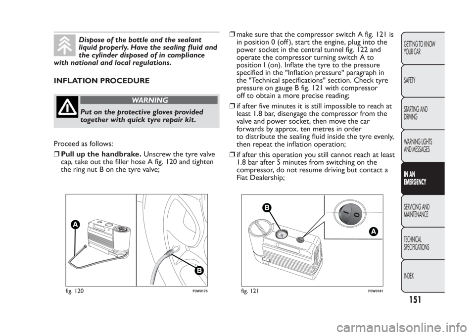
❒Pull up the handbrake.Unscrew the tyre valve
cap, take out the filler hose A fig. 120 and tighten
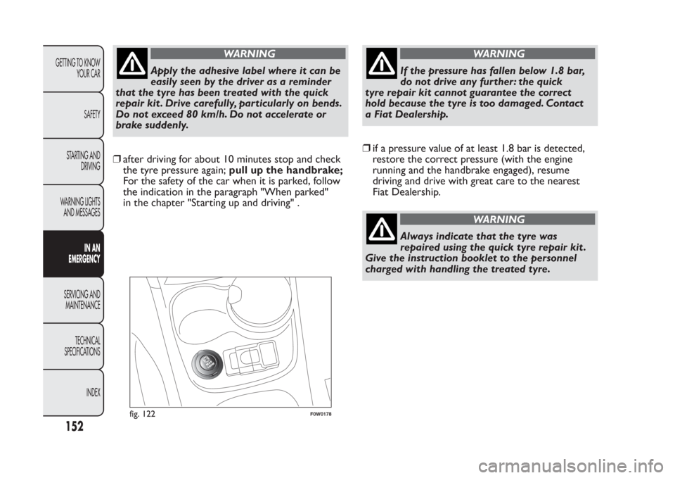
the ring nut B on the tyre valve;❒make sure that the compressor switch A fig. 121 is
in position 0 (off ), start the engine, plug into the
power socket in the central tunnel fig. 122 and
operate the compressor turning switch A to
position I (on). Inflate the tyre to the pressure
specified in the "Inflation pressure" paragraph in
the "Technical specifications" section. Check tyre
pressure on gauge B fig. 121 with compressor
off to obtain a more precise reading;
❒if after five minutes it is still impossible to reach at
least 1.8 bar, disengage the compressor from the
valve and power socket, then move the car
forwards by approx. ten metres in order
to distribute the sealing fluid inside the tyre evenly,
then repeat the inflation operation;
❒if after this operation you still cannot reach at least
1.8 bar after 5 minutes from switching on the
compressor, do not resume driving but contact a
Fiat Dealership;
fig. 120
F0W0176
fig. 121
F0W0181
151GETTING TO KNOW
YOUR CAR
SAFETY
STARTING AND
DRIVING
WARNING LIGHTS
AND MESSAGESIN AN
EMERGENCYSERVICING AND
MAINTENANCE
TECHNICAL
SPECIFICATIONS
INDEX
Page 156 of 284
WARNING
Apply the adhesive label where it can be
easily seen by the driver as a reminder
that the tyre has been treated with the quick
repair kit . Drive carefully, particularly on bends.
Do not exceed 80 km/h. Do not accelerate or
brake suddenly.
❒after driving for about 10 minutes stop and check
the tyre pressure again;pull up the handbrake;
For the safety of the car when it is parked, follow
the indication in the paragraph "When parked"
in the chapter "Starting up and driving" .
WARNING
If the pressure has fallen below 1.8 bar,
do not drive any further: the quick
tyre repair kit cannot guarantee the correct
hold because the tyre is too damaged. Contact
a Fiat Dealership.
❒if a pressure value of at least 1.8 bar is detected,
restore the correct pressure (with the engine
running and the handbrake engaged), resume
driving and drive with great care to the nearest
Fiat Dealership.
WARNING
Always indicate that the tyre was
repaired using the quick tyre repair kit .
Give the instruction booklet to the personnel
charged with handling the treated tyre.
fig. 122
F0W0178
152
GETTING TO KNOW
YOUR CAR
SAFETY
STARTING AND
DRIVING
WARNING LIGHTS
AND MESSAGES
IN AN
EMERGENCY
SERVICING AND
MAINTENANCE
TECHNICAL
SPECIFICATIONS
INDEX
Page 170 of 284
WARNING
If a general fuse (MEGA-FUSE,
MIDI-FUSE, MAXI-FUSE) blows contact
a Fiat Dealership.
WARNING
Before replacing a fuse, make sure that
the ignition key has been removed
and that all the other services are switched off
and/or disengaged.
WARNING
If a general protection fuse for safety
systems (air bag system, braking system),
power unit systems (engine system, transmission
system) or steering system is triggered, contact
a Fiat Dealership.
166
GETTING TO KNOW
YOUR CAR
SAFETY
STARTING AND
DRIVING
WARNING LIGHTS
AND MESSAGES
IN AN
EMERGENCY
SERVICING AND
MAINTENANCE
TECHNICAL
SPECIFICATIONS
INDEX
Page 171 of 284
FUSE LOCATION
Engine compartment fuse box
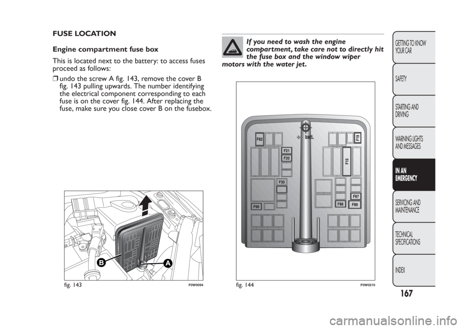
This is located next to the battery: to access fuses
proceed as follows:
❒undo the screw A fig. 143, remove the cover B
fig. 143 pulling upwards. The number identifying
the electrical component corresponding to each
fuse is on the cover fig. 144. After replacing the
fuse, make sure you close cover B on the fusebox.
If you need to wash the engine
compartment , take care not to directly hit
the fuse box and the window wiper
motors with the water jet .
fig. 143
F0W0094
fig. 144
F0W0210
167GETTING TO KNOW
YOUR CAR
SAFETY
STARTING AND
DRIVING
WARNING LIGHTS
AND MESSAGESIN AN
EMERGENCYSERVICING AND
MAINTENANCE
TECHNICAL
SPECIFICATIONS
INDEX
Page 173 of 284
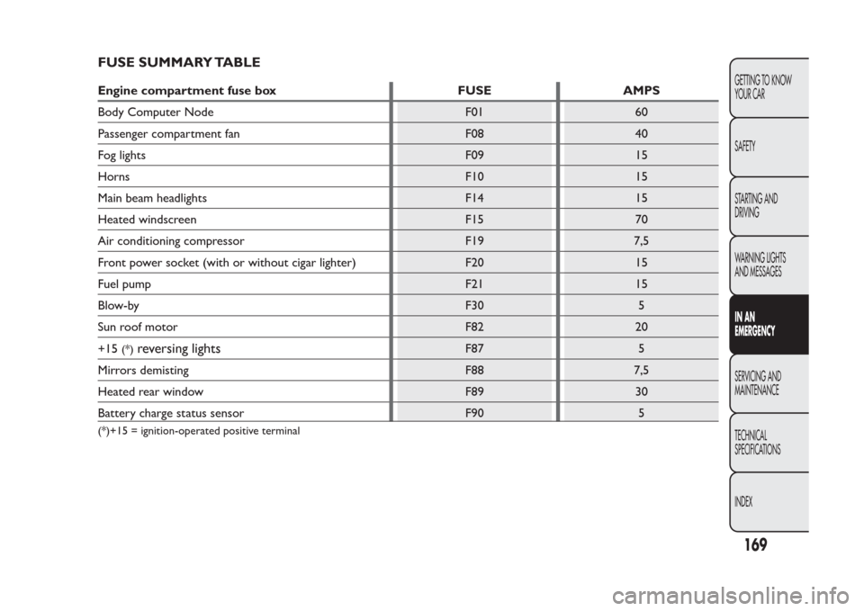
FUSE SUMMARY TABLEEngine compartment fuse box FUSE AMPS
Body Computer Node F01 60
Passenger compartment fan F08 40
Fog lights F09 15
Horns F10 15
Main beam headlights F14 15
Heated windscreen F15 70
Air conditioning compressor F19 7,5
Front power socket (with or without cigar lighter) F20 15
Fuel pump F21 15
Blow-by F30 5
Sun roof motor F82 20
+15
(*)
reversing lights
F87 5
Mirrors demisting F88 7,5
Heated rear window F89 30
Battery charge status sensor F90 5
(*)+15 = ignition-operated positive terminal
169GETTING TO KNOW
YOUR CAR
SAFETY
STARTING AND
DRIVING
WARNING LIGHTS
AND MESSAGESIN AN
EMERGENCYSERVICING AND
MAINTENANCE
TECHNICAL
SPECIFICATIONS
INDEX
Page 174 of 284
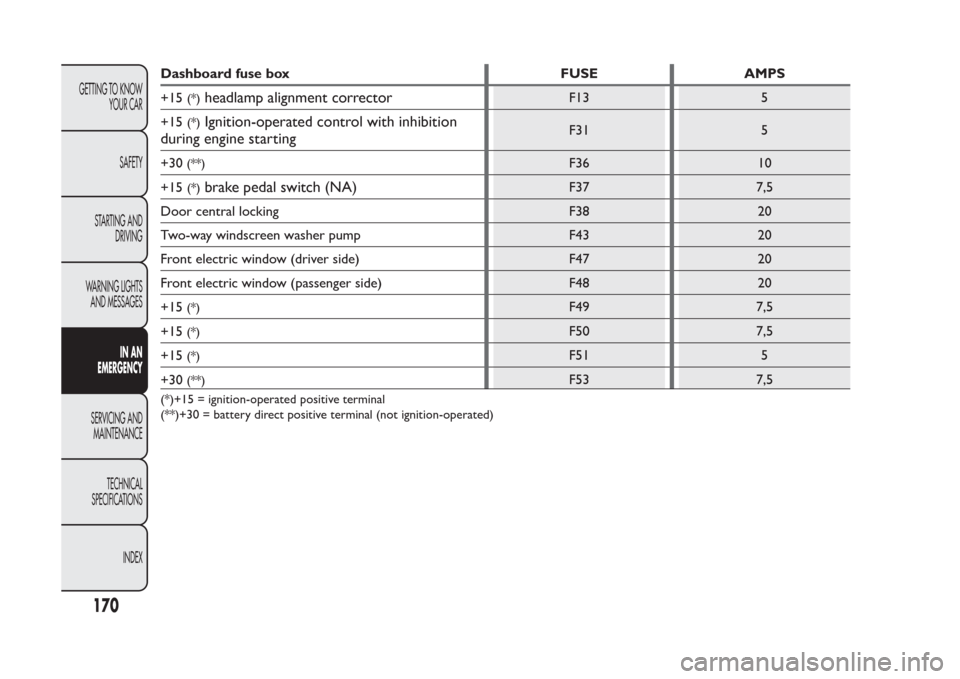
Dashboard fuse box FUSE AMPS
+15
(*)
headlamp alignment corrector
F13 5
+15
(*)
Ignition-operated control with inhibition
during engine starting
F31 5
+30
(**)
F36 10
+15
(*)
brake pedal switch (NA)
F37 7,5
Door central locking F38 20
Two-way windscreen washer pump F43 20
Front electric window (driver side) F47 20
Front electric window (passenger side) F48 20
+15
(*)
F49 7,5
+15
(*)
F50 7,5
+15
(*)
F51 5
+30
(**)
F53 7,5
(*)+15 = ignition-operated positive terminal
(**)+30 = battery direct positive terminal (not ignition-operated)
170
GETTING TO KNOW
YOUR CAR
SAFETY
STARTING AND
DRIVING
WARNING LIGHTS
AND MESSAGES
IN AN
EMERGENCY
SERVICING AND
MAINTENANCE
TECHNICAL
SPECIFICATIONS
INDEX