Esc FIAT PANDA 2014 319 / 3.G Owners Manual
[x] Cancel search | Manufacturer: FIAT, Model Year: 2014, Model line: PANDA, Model: FIAT PANDA 2014 319 / 3.GPages: 284, PDF Size: 11.54 MB
Page 5 of 284
Dear Customer,
We would like to congratulate and thank you for choosing Fiat.
We have written this handbook to help you get to know all the features of your car and use it in the best possible way.
You are recommended to read it right through before taking to the road for the first time.
It contains important information, advice and instructions for the use of the car which will help you get the very best out
of your Fiat. The handbook also provides a description of special features and tips as well as essential information for
correct care, maintenance, safe car driving and use and preservation of your Fiat over time.
Carefully read the warnings and indications marked with the following symbols:
personal safety;car safety;environmental protection.
The enclosed Warranty Booklet lists the services that Fiat offers to its Customers:
❒the Warranty Certificate with terms and conditions for maintaining its validity;
❒the range of additional services available to Fiat Customers.
We are sure that these will help you get in touch with your new car and appreciate it and the care provided by the
people at Fiat.
Enjoy reading. Happy motoring!
This Owner Handbook describes all the versions of the Fiat Panda. As a
consequence, you should only consider the information which is related to the trim
level, engine and version that you have purchased. All data contained in this
publication are purely indicative. Fiat Group Automobiles can modify the
specifications of the vehicle model described in this publication at any time, for
technical or commercial reasons. For further information, contact a Fiat Dealership.
Page 14 of 284
MENU ITEMSMenu
This option allows you to access the Setup Menu.
Press the
or
fig. 7 button to select the
various Menu items. Hold down the
button to
return to the standard screen.
Lighting (Interior car lighting adjustment)
(with side lights on only)
With the side lights on, this function is used to set
the brightness of the instrument panel, radio
controls and automatic climate control system
controls (for versions/markets, where provided) to 8
levels.
To adjust the brightness, proceed as follows:
press the
button briefly: the previously set level
will flash on the display;
press the
or
button to adjust the brightness
level;
press the
button briefly to return to the menu
screen or hold the button down to return to the
standard screen without storing.Speed Beep (Speed limit)
This function is used to set the car speed limit (km/h
or mph); the driver is alerted when this limit is
exceeded.
To set the desired speed limit, proceed as follows:
❒briefly press the
button: the display will show
the text (Speed Beep);
❒press the
or
button to select speed limit
activation (On) or deactivation (Off );
❒if the function is on, press
or
to select the
desired speed limit and then pressto confirm.
NoteSetting is possible between 30 and 200 km/h,
or 20 and 125 mph, according to the previously
set unit. See the "Measurement unit adjustment
(Measurement unit)" paragraph described below. The
setting will increase/decrease by 5 units each time
the
/
button is pressed. Hold down the
/
button to automatically increase/decrease
the setting rapidly. Complete the adjustment with
single presses of the button when you approach the
desired value.
❒press the
button briefly to return to the menu
screen or hold the button down to return to the
standard screen without storing.
To cancel the setting, proceed as follows:
❒press thebutton briefly: "On" will flash on the
display;
10GETTING TO
KNOW YOUR CAR
SAFETY
STARTING AND
DRIVING
WARNING LIGHTS
AND MESSAGES
IN AN EMERGENCY
SERVICING AND
MAINTENANCE
TECHNICAL
SPECIFICATIONS
INDEX
Page 21 of 284
Average speed
This shows the average car speed as a function of the
overall time elapsed since the start of the new
journey.
Tr i p t i m e
The time elapsed since the start of a new journey.
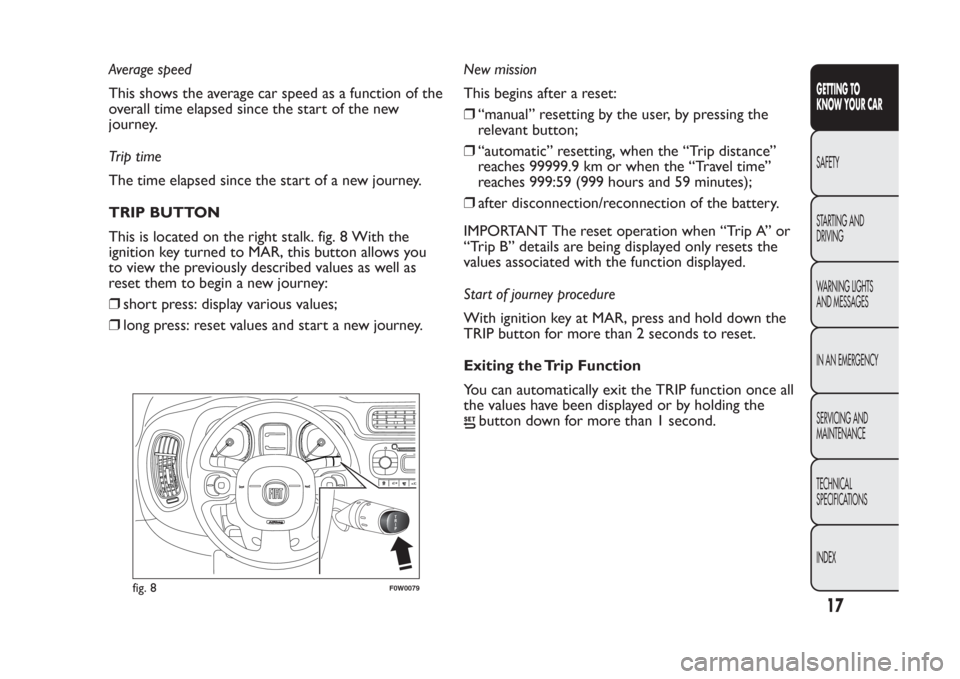
TRIP BUTTON
This is located on the right stalk. fig. 8 With the
ignition key turned to MAR, this button allows you
to view the previously described values as well as
reset them to begin a new journey:
❒short press: display various values;
❒long press: reset values and start a new journey.New mission
This begins after a reset:
❒“manual” resetting by the user, by pressing the
relevant button;
❒“automatic” resetting, when the “Trip distance”
reaches 99999.9 km or when the “Travel time”
reaches 999:59 (999 hours and 59 minutes);
❒after disconnection/reconnection of the battery.
IMPORTANT The reset operation when “Trip A” or
“Trip B” details are being displayed only resets the
values associated with the function displayed.
Start of journey procedure
With ignition key at MAR, press and hold down the
TRIP button for more than 2 seconds to reset.
Exiting the Trip Function
You can automatically exit the TRIP function once all
the values have been displayed or by holding the
button down for more than 1 second.
1
02
fig. 8
F0W0079
17GETTING TO
KNOW YOUR CARSAFETY
STARTING AND
DRIVING
WARNING LIGHTS
AND MESSAGES
IN AN EMERGENCY
SERVICING AND
MAINTENANCE
TECHNICAL
SPECIFICATIONS
INDEX
Page 39 of 284
❒press button E to turn the climate control system
on; the LED on the button will switch on;
❒turn knob E to the desired speed.
Cooling adjustment
❒turn knob A fig. 29 to the right to increase the
temperature;
❒turn knob B to external air recirculation
;
❒turn knob E to the desired speed;
PASSENGER COMPARTMENT HEATING
For optimal heating of the passenger compartment,
proceed as follows:
❒turn knob A fig. 29to the red section;
❒turn knob C to the desired symbol;
❒turn knob E to the desired speed.
FAST PASSENGER COMPARTMENT
HEATING
For fast heating of the passenger compartment,
proceed as follows:
❒turn knob A fig. 29to the red section;
❒Turn the knob to internal air recirculation
;
❒turn knob C to
;
❒turn knob E to 4
(max. fan speed).
Then use the controls to maintain the required
comfort conditions and turn knob B to the outside
air intake symbol.IMPORTANT With a cold engine, you have to wait
for a few minutes to let the system fluid reach
optimum operating temperature.
Fast windscreen and front side window
demisting/defrosting (MAX-DEF)
Proceed as follows:
❒turn knob A to the red section;
❒turn knob B to
;
❒turn knob C to
;
❒turn knob E to 4 (maximum fan speed).
IMPORTANT The climate control system is very
useful for speeding up demisting since it dehumidifies
the air. Adjust the controls as described above and
press knob E
to switch the climate control system
on (the LED on the knob will switch on - for
versions/markets, where provided).
Heated rear window demisting/defrosting
Press the
button to activate: when this function is
activated, the button LED switches on.
For versions/markets where provided, press the
button to activate also demisting/defrosting
of windscreen (with engine running only) and door
mirrors (for versions/markets, where provided).
This function is timed and switches off automatically
after 4 minutes for the windscreen and 20 minutes
for the rear window and door mirrors. Press the
button
again to switch the function off in advance.
35GETTING TO
KNOW YOUR CARSAFETY
STARTING AND
DRIVING
WARNING LIGHTS
AND MESSAGES
IN AN EMERGENCY
SERVICING AND
MAINTENANCE
TECHNICAL
SPECIFICATIONS
INDEX
Page 43 of 284
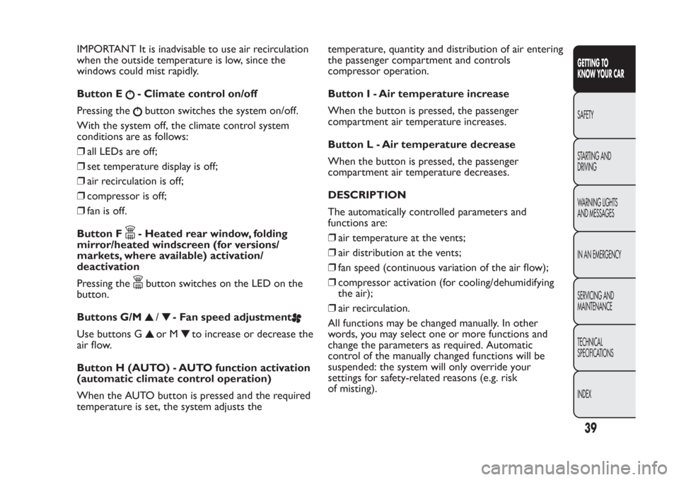
IMPORTANT It is inadvisable to use air recirculation
when the outside temperature is low, since the
windows could mist rapidly.
Button E
- Climate control on/off
Pressing thebutton switches the system on/off.
With the system off, the climate control system
conditions are as follows:
❒all LEDs are off;
❒set temperature display is off;
❒air recirculation is off;
❒compressor is off;
❒fan is off.
Button F- Heated rear window, folding
mirror/heated windscreen (for versions/
markets, where available) activation/
deactivation
Pressing thebutton switches on the LED on the
button.
Buttons G/M
/
- Fan speed adjustment
Use buttons G
or M
to increase or decrease the
air flow.
Button H (AUTO) - AUTO function activation
(automatic climate control operation)
When the AUTO button is pressed and the required
temperature is set, the system adjusts thetemperature, quantity and distribution of air entering
the passenger compartment and controls
compressor operation.
Button I - Air temperature increase
When the button is pressed, the passenger
compartment air temperature increases.
Button L - Air temperature decrease
When the button is pressed, the passenger
compartment air temperature decreases.
DESCRIPTION
The automatically controlled parameters and
functions are:
❒air temperature at the vents;
❒air distribution at the vents;
❒fan speed (continuous variation of the air flow);
❒compressor activation (for cooling/dehumidifying
the air);
❒air recirculation.
All functions may be changed manually. In other
words, you may select one or more functions and
change the parameters as required. Automatic
control of the manually changed functions will be
suspended: the system will only override your
settings for safety-related reasons (e.g. risk
of misting).
39GETTING TO
KNOW YOUR CARSAFETY
STARTING AND
DRIVING
WARNING LIGHTS
AND MESSAGES
IN AN EMERGENCY
SERVICING AND
MAINTENANCE
TECHNICAL
SPECIFICATIONS
INDEX
Page 52 of 284
A further stroke after approximately six seconds
completes the wiping cycle.
REAR WINDOW WASHER/ WIPER
It can be operated only with the ignition key turned
to MAR-ON.
Activation
Turn ring nut B fig. 32 from positionOto position
to operate the rear window wiper as follows:
❒in intermittent mode when the windscreen wiper
is not operating;
❒in synchronous mode (at half the speed of the
windscreen wiper) when the windscreen wiper
is operating;
❒in continuous mode with reverse gear engaged and
the control active.
With the windscreen wiper on and reverse gear
engaged, rear window wiping will be continuous.
Pushing the stalk towards the dashboard (unstable
position) the rear window washer jet will activate.
Keep the stalk pushed for more than half a second to
activate the rear window wiper as well. Releasing
the stalk will activate the smart washing function, as
described for the windscreen wiper.
The function stops when the stalk is released.
Do not use the rear window wiper to
removelayersofsnoworice.Inthese
conditions, the windscreen wiper may be
submitted to excessive effor t resulting in the
motor protection cutting in and wiper operation
being inhibited for a few seconds. If operation
is not restored, contact a Fiat Dealership.
48GETTING TO
KNOW YOUR CAR
SAFETY
STARTING AND
DRIVING
WARNING LIGHTS
AND MESSAGES
IN AN EMERGENCY
SERVICING AND
MAINTENANCE
TECHNICAL
SPECIFICATIONS
INDEX
Page 61 of 284
WARNING
When leaving the car, always remove the
key from the ignition to avoid the risk
of injur y to those still inside the car due to
accidental operation of the sunroof. Improper
use of the roof may be dangerous. Before and
during operation, always check that no-one
is exposed to the risk of being injured by the
moving sunroof or by objects getting caught or
hitbyit.
ANTI-PINCH SAFETY DEVICE
For versions/markets where provided, the sun roof
has an anti-pinch safety system capable of detecting
the presence of an obstacle whilst the roof is closing;
if this happens, the system intervenes and the
movement of the glass is immediately reversed.
EMERGENCY OPERATION
If the electric device for moving the roof fails, the
sun roof can be moved manually proceeding as
described below:
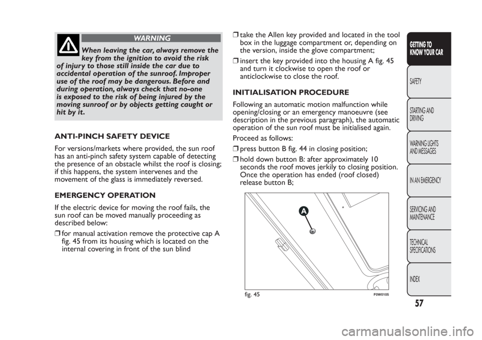
❒for manual activation remove the protective cap A
fig. 45 from its housing which is located on the
internal covering in front of the sun blind❒take the Allen key provided and located in the tool
box in the luggage compartment or, depending on
the version, inside the glove compartment;
❒insert the key provided into the housing A fig. 45
and turn it clockwise to open the roof or
anticlockwise to close the roof.
INITIALISATION PROCEDURE
Following an automatic motion malfunction while
opening/closing or an emergency manoeuvre (see
description in the previous paragraph), the automatic
operation of the sun roof must be initialised again.
Proceed as follows:
❒press button B fig. 44 in closing position;
❒hold down button B: after approximately 10
seconds the roof moves jerkily to closing position.
Once the operation has ended (roof closed)
release button B;
fig. 45
F0W0105
57GETTING TO
KNOW YOUR CARSAFETY
STARTING AND
DRIVING
WARNING LIGHTS
AND MESSAGES
IN AN EMERGENCY
SERVICING AND
MAINTENANCE
TECHNICAL
SPECIFICATIONS
INDEX
Page 70 of 284
❒partial extension on the right side, with folded
backrest, for transporting two passengers on
the left side;
❒partial extension on the left side, with folded
backrest, for transporting one passengers on the
right side.
Repositioning the rear seat: move the seat belts to
the side, making sure that they are correctly
extended and not twisted. Lift up the backrest folded
previously until a click is heard for the engagement
mechanism.
Extending the boot with rear sliding seat
Partial
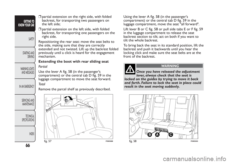
Use the lever A fig. 58 (in the passenger's
compartment) or the central tab D fig. 59 in the
luggage compartment to move the seat forward.
Total
Remove the parcel shelf as previously described.Using the lever A fig. 58 (in the passenger's
compartment) or the central tab D fig. 59 in the
luggage compartment, move the seat "all forward".
Lift lever B or C fig. 58 or pull side tabs E or F fig. 59
in the luggage compartment to release the seat
backrest section to tilt; act on both if you want to
tilt the whole backrest.
To bring back the seat in its standard position, lift the
backrest and push it backwards until you hear the
locking click and make sure the seat belts are at the
front of the backrest.
WARNING
Once you have released the adjustment
lever, always check that the seat is
locked on the guides by trying to move it back
and for th. Failure to lock the seat in place could
result in the seat moving suddenly.
fig. 57
F0W0088
fig. 58
F0W0303
66GETTING TO
KNOW YOUR CAR
SAFETY
STARTING AND
DRIVING
WARNING LIGHTS
AND MESSAGES
IN AN EMERGENCY
SERVICING AND
MAINTENANCE
TECHNICAL
SPECIFICATIONS
INDEX
Page 78 of 284
ESC SYSTEM (Electronic Stability
Control)(for versions/markets, where provided)
This is an electronic system that controls car stability
in the event of tyre grip loss, helping maintain
directional control. The system is capable of
recognising potentially dangerous situations in terms
of the stability and intervenes automatically on the
brakes in a differentiated manner for the four wheels
in order to provide a stabilizing torque.
The ESC system also includes the following
subsystems:
❒Hill Holder
❒ASR
❒HBA
❒ABS
❒EBD
SYSTEM INTERVENTION
It is signalled by the flashing of theESCwarning light
on the instrument panel, to inform the driver that
the car is in critical stability and grip conditions.
SYSTEM ACTIVATION
The ESC system switches on automatically when the
engine is started and cannot be switched off.HILL HOLDER SYSTEM
This system is an integral part of the ESC system and
facilitates starting on slopes.
It is activated automatically in the following instances:
❒uphill: car stationary on a road with a gradient
higher than 5%, engine running, brake pressed and
gearbox in neutral or gear (other than reverse)
engaged;
❒downhill: car stationary on a road with a gradient
higher than 5%, engine running, brake pressed and
reverse gear engaged.
When setting off, the ESC system control unit
maintains braking pressure on the wheels until the
torque required for starting is reached or, in any
case, for a maximum of 2 seconds so that the right
foot can be moved easily from the brake pedal to the
accelerator pedal.
When 2 seconds have elapsed, without any
departure having taken place, the system is
automatically deactivated, gradually releasing the
braking pressure. During this release stage, a typical
mechanical brake release noise can be heard,
indicating that the car is about to move.
NOTE: the Hill Holder system is not active with
engaged parking brake.
74GETTING TO
KNOW YOUR CAR
SAFETY
STARTING AND
DRIVING
WARNING LIGHTS
AND MESSAGES
IN AN EMERGENCY
SERVICING AND
MAINTENANCE
TECHNICAL
SPECIFICATIONS
INDEX
Page 79 of 284
IMPORTANT The Hill Holder system is not a parking
brake; therefore, never leave the vehicle without
having engaged the handbrake, turned the engine off
and engaged the first gear, so that the parked vehicle
is in safe conditions (further read the paragraph
"When parked" in the chapter "Starting and driving").
ASR SYSTEM (AntiSlip Regulation)
It is an integral part of the ESC system. It
automatically operates in the event of drive wheels
slipping, loss of grip on wet roads (aquaplaning)
and acceleration on slippery, snowy or icy roads,
etc…
Depending on the slipping conditions, two different
control systems are activated:
❒if the slipping involves both drive wheels, the ASR
intervenes reducing the power transmitted by the
engine;
❒if the slipping only involves one of the drive
wheels, it intervenes automatically braking the
wheel that is slipping.Activation/deactivation of the ASR system
The ASR system activates automatically each time
the engine is started.
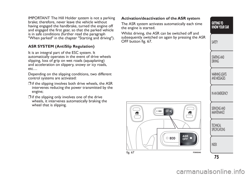
Whilst driving, the ASR can be switched off and
subsequently switched on again by pressing the ASR
OFF button fig. 67.
fig. 67
F0W0040
75GETTING TO
KNOW YOUR CARSAFETY
STARTING AND
DRIVING
WARNING LIGHTS
AND MESSAGES
IN AN EMERGENCY
SERVICING AND
MAINTENANCE
TECHNICAL
SPECIFICATIONS
INDEX