warning FIAT PANDA 2018 Owner handbook (in English)
[x] Cancel search | Manufacturer: FIAT, Model Year: 2018, Model line: PANDA, Model: FIAT PANDA 2018Pages: 228, PDF Size: 17.05 MB
Page 18 of 228
DOOR MIRRORS
15)
Manual adjustment
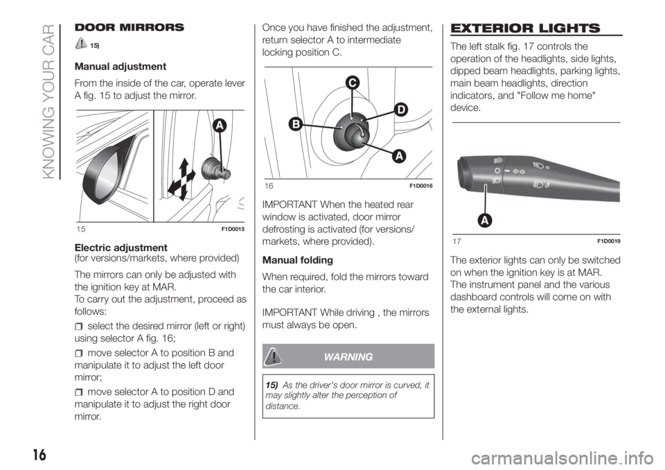
From the inside of the car, operate lever
A fig. 15 to adjust the mirror.
Electric adjustment
(for versions/markets, where provided)
The mirrors can only be adjusted with
the ignition key at MAR.
To carry out the adjustment, proceed as
follows:
select the desired mirror (left or right)
using selector A fig. 16;
move selector A to position B and
manipulate it to adjust the left door
mirror;
move selector A to position D and
manipulate it to adjust the right door
mirror.Once you have finished the adjustment,
return selector A to intermediate
locking position C.
IMPORTANT When the heated rear
window is activated, door mirror
defrosting is activated (for versions/
markets, where provided).
Manual folding
When required, fold the mirrors toward
the car interior.
IMPORTANT While driving , the mirrors
must always be open.
WARNING
15)As the driver's door mirror is curved, it
may slightly alter the perception of
distance.
EXTERIOR LIGHTS
The left stalk fig. 17 controls the
operation of the headlights, side lights,
dipped beam headlights, parking lights,
main beam headlights, direction
indicators, and "Follow me home"
device.
The exterior lights can only be switched
on when the ignition key is at MAR.
The instrument panel and the various
dashboard controls will come on with
the external lights.
15F1D0015
16F1D0016
A
17F1D0019
16
KNOWING YOUR CAR
Page 19 of 228
SIDE LIGHTS / DAYTIME
RUNNING LIGHTS (DRL)
"Daytime Running Lights"
(for versions/markets, where provided)
16) 17)
With the ignition key in MAR position
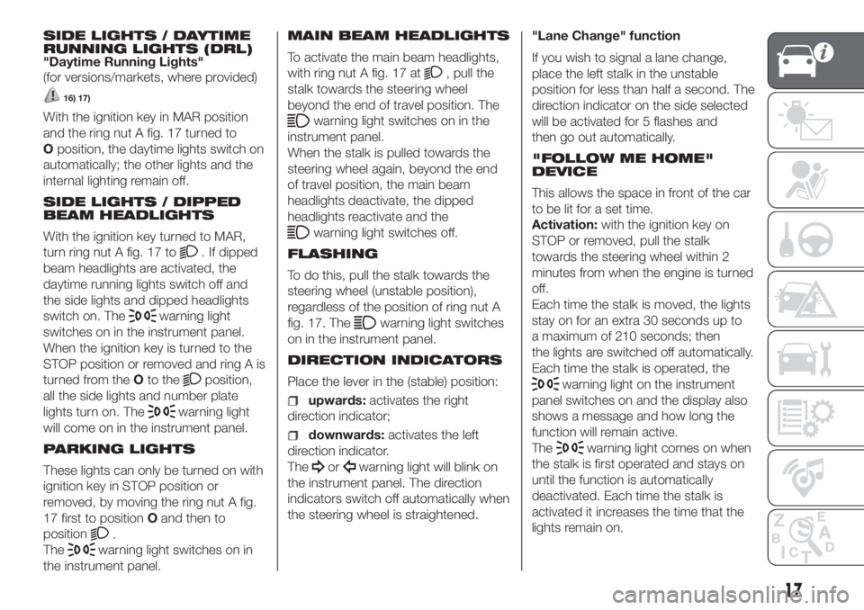
and the ring nut A fig. 17 turned to
Oposition, the daytime lights switch on
automatically; the other lights and the
internal lighting remain off.
SIDE LIGHTS / DIPPED
BEAM HEADLIGHTS
With the ignition key turned to MAR,
turn ring nut A fig. 17 to
. If dipped
beam headlights are activated, the
daytime running lights switch off and
the side lights and dipped headlights
switch on. The
warning light
switches on in the instrument panel.
When the ignition key is turned to the
STOP position or removed and ring A is
turned from theOto the
position,
all the side lights and number plate
lights turn on. The
warning light
will come on in the instrument panel.
PARKING LIGHTS
These lights can only be turned on with
ignition key in STOP position or
removed, by moving the ring nut A fig.
17 first to positionOand then to
position
.
The
warning light switches on in
the instrument panel.MAIN BEAM HEADLIGHTS
To activate the main beam headlights,
with ring nut A fig. 17 at
, pull the
stalk towards the steering wheel
beyond the end of travel position. The
warning light switches on in the
instrument panel.
When the stalk is pulled towards the
steering wheel again, beyond the end
of travel position, the main beam
headlights deactivate, the dipped
headlights reactivate and the
warning light switches off.
FLASHING
To do this, pull the stalk towards the
steering wheel (unstable position),
regardless of the position of ring nut A
fig. 17. The
warning light switches
on in the instrument panel.
DIRECTION INDICATORS
Place the lever in the (stable) position:
upwards:activates the right
direction indicator;
downwards:activates the left
direction indicator.
The
orwarning light will blink on
the instrument panel. The direction
indicators switch off automatically when
the steering wheel is straightened."Lane Change" function
If you wish to signal a lane change,
place the left stalk in the unstable
position for less than half a second. The
direction indicator on the side selected
will be activated for 5 flashes and
then go out automatically.
"FOLLOW ME HOME"
DEVICE
This allows the space in front of the car
to be lit for a set time.
Activation:with the ignition key on
STOP or removed, pull the stalk
towards the steering wheel within 2
minutes from when the engine is turned
off.
Each time the stalk is moved, the lights
stay on for an extra 30 seconds up to
a maximum of 210 seconds; then
the lights are switched off automatically.
Each time the stalk is operated, the
warning light on the instrument
panel switches on and the display also
shows a message and how long the
function will remain active.
The
warning light comes on when
the stalk is first operated and stays on
until the function is automatically
deactivated. Each time the stalk is
activated it increases the time that the
lights remain on.
17
Page 20 of 228
Deactivation:keep the stalk pulled
towards the steering wheel for more
than two seconds.
REAR FOG LIGHTS
Press the
button, on the dashboard,
to switch on the rear fog lights.
With rear fog lights on, the
warning
light on the instrument panel will come
on at the same time.
FRONT/REAR FOG
LIGHTS
(for versions/markets, where provided)
The fog lights can be activated only
when the dipped beam headlights are
on.
To turn on the front/rear fog lights,
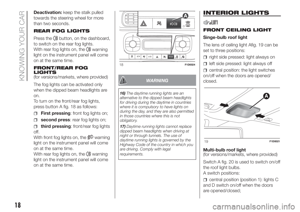
press button A fig. 18 as follows:
First pressing: front fog lights on;
second press: rear fog lights on;
third pressing: front/rear fog lights
off.
With front fog lights on, the
warning
light on the instrument panel will come
on at the same time.
With rear fog lights on, the
warning
light on the instrument panel will come
on at the same time.
WARNING
16)The daytime running lights are an
alternative to the dipped beam headlights
for driving during the daytime in countries
where it is compulsory to have lights on
during the day, and they are also permitted
in those countries where this is not
obligatory.
17)Daytime running lights cannot replace
dipped beam headlights when driving at
night or through tunnels. The use of
daytime running lights is governed by the
Highway Code of the country in which you
are driving. Comply with legal
requirements.
INTERIOR LIGHTS
FRONT CEILING LIGHT
Singe-bulb roof light
The lens of ceiling light Afig. 19 can be
set to three positions:
right side pressed: light always on
left side pressed: light always off
central position: the light switches
on/off when the doors are opened/
closed.
Multi-bulb roof light
(for versions/markets, where provided)
Switch A fig. 20 is used to switch on/off
the roof light bulbs.
A switch positions:
central position (position 1): lights C
and D switch on/off when the doors
are opened/closed;
18F1D0024
19F1D0021
18
KNOWING YOUR CAR
Page 22 of 228
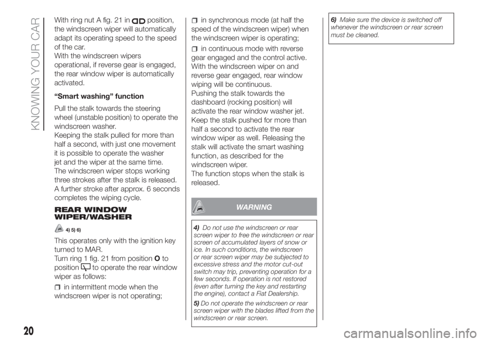
With ring nut A fig. 21 inposition,
the windscreen wiper will automatically
adapt its operating speed to the speed
of the car.
With the windscreen wipers
operational, if reverse gear is engaged,
the rear window wiper is automatically
activated.
“Smart washing” function
Pull the stalk towards the steering
wheel (unstable position) to operate the
windscreen washer.
Keeping the stalk pulled for more than
half a second, with just one movement
it is possible to operate the washer
jet and the wiper at the same time.
The windscreen wiper stops working
three strokes after the stalk is released.
A further stroke after approx. 6 seconds
completes the wiping cycle.
REAR WINDOW
WIPER/WASHER
4) 5) 6)
This operates only with the ignition key
turned to MAR.
Turn ring 1 fig. 21 from positionOto
position
to operate the rear window
wiper as follows:
in intermittent mode when the
windscreen wiper is not operating;
in synchronous mode (at half the
speed of the windscreen wiper) when
the windscreen wiper is operating;
in continuous mode with reverse
gear engaged and the control active.
With the windscreen wiper on and
reverse gear engaged, rear window
wiping will be continuous.
Pushing the stalk towards the
dashboard (rocking position) will
activate the rear window washer jet.
Keep the stalk pushed for more than
half a second to activate the rear
window wiper as well. Releasing the
stalk will activate the smart washing
function, as described for the
windscreen wiper.
The function stops when the stalk is
released.
WARNING
4)Do not use the windscreen or rear
screen wiper to free the windscreen or rear
screen of accumulated layers of snow or
ice. In such conditions, the windscreen
or rear screen wiper may be subjected to
excessive stress and the motor cut-out
switch may trip, preventing operation for a
few seconds. If operation is not restored
(even after turning the key and restarting
the engine), contact a Fiat Dealership.
5)Do not operate the windscreen or rear
screen wiper with the blades lifted from the
windscreen or rear screen.6)Make sure the device is switched off
whenever the windscreen or rear screen
must be cleaned.
20
KNOWING YOUR CAR
Page 26 of 228
towards the footwell diffusers. Due to the natural tendency of heat to spread upwards, this type of distribution warms the
passenger compartment up as quickly as possible, providing an immediate feeling of warmth.
+distribution between feet area diffusers (warmest air) and dashboard diffusers (coolest air).
+distribution between feet area diffusers and windscreen/front side window diffusers. This type of distribution achieves
effective heating of the passenger compartment and prevents the windows from misting up.
IMPORTANT In warm-humid weather conditions, using cold air on the windscreen may cause external condensation, which
could limit visibility.
E - Turns on/off the MAX-DEF function (fast front window defrosting/demisting).
F - Turns on/off the air conditioning compressor.
G - Turns on/off the internal air recirculation.
H - Climate control on/off.
F - Turns on/off the heated rear window and (for versions/markets, where available) the heated mirrors/heated windscreen.
L/M - Adjusts the fan speed.
The automatic climate control manages the Start&Stop function (engine off when the car speed is zero) to guarantee a suitable
comfort inside the passenger compartment.
NOTE In particularly severe climate conditions it is recommended to limit the use of the Start&Stop function to prevent the
compressor from continuously switching on and off, with consequent rapid misting of the windows and accumulation of
humidity with unpleasant smells in the passenger compartment.
.
WARNING
18)It is advisable not to use the air recirculation function when the outside temperature is low to prevent the windows from rapidly misting up.
WARNING
2)The system uses a coolant that is compatible with the laws in force in countries where the vehicle is sold, R134a or R1234yf. When
charging, only use the gas indicated on the dedicated plate in the engine compartment . The use of other coolants affects the efficiency and
condition of the system. The lubricant used for the compressor is also strictly linked to the type of cooling gas, please refer to a Fiat
Dealership.
24
KNOWING YOUR CAR
Page 27 of 228
ELECTRIC WINDOWS
ELECTRIC FRONT
WINDOWS
19) 20)
These operate when the ignition key is
turned to MAR and for about three
minutes after turning the ignition key to
STOP or removing it.
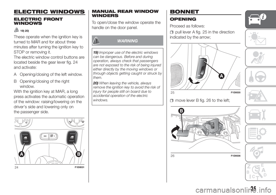
The electric window control buttons are
located beside the gear lever fig. 24
and activate:
A Opening/closing of the left window.
B Opening/closing of the right
window.
With the ignition key at MAR, a long
press activates the automatic operation
of the window: raising/lowering on the
driver's side and lowering only on
the passenger side.MANUAL REAR WINDOW
WINDERS
To open/close the window operate the
handle on the door panel.WARNING
19)Improper use of the electric windows
can be dangerous. Before and during
operation, always check that passengers
are not exposed to the risk of being injured
either directly by the moving windows or
through objects getting caught or struck by
them.
20)When leaving the vehicle, always
remove the ignition key to avoid the risk of
injury for people still on board due to
accidental operation of the electric
windows.
BONNET
OPENING
Proceed as follows:
pull lever A fig. 25 in the direction
indicated by the arrow;
move lever B fig. 26 to the left;
24F1D0031
25F1D0035
26F1D0036
25
Page 28 of 228
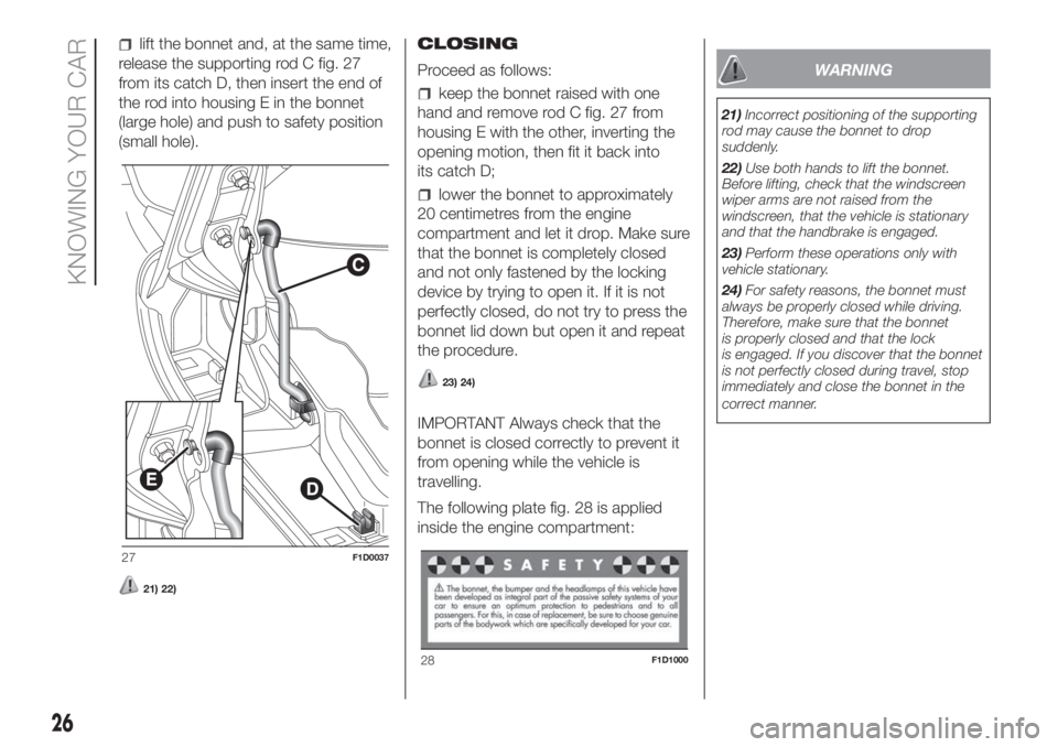
lift the bonnet and, at the same time,
release the supporting rod C fig. 27
from its catch D, then insert the end of
the rod into housing E in the bonnet
(large hole) and push to safety position
(small hole).
21) 22)
CLOSING
Proceed as follows:
keep the bonnet raised with one
hand and remove rod C fig. 27 from
housing E with the other, inverting the
opening motion, then fit it back into
its catch D;
lower the bonnet to approximately
20 centimetres from the engine
compartment and let it drop. Make sure
that the bonnet is completely closed
and not only fastened by the locking
device by trying to open it. If it is not
perfectly closed, do not try to press the
bonnet lid down but open it and repeat
the procedure.
23) 24)
IMPORTANT Always check that the
bonnet is closed correctly to prevent it
from opening while the vehicle is
travelling.
The following plate fig. 28 is applied
inside the engine compartment:
WARNING
21)Incorrect positioning of the supporting
rod may cause the bonnet to drop
suddenly.
22)Use both hands to lift the bonnet.
Before lifting, check that the windscreen
wiper arms are not raised from the
windscreen, that the vehicle is stationary
and that the handbrake is engaged.
23)Perform these operations only with
vehicle stationary.
24)For safety reasons, the bonnet must
always be properly closed while driving.
Therefore, make sure that the bonnet
is properly closed and that the lock
is engaged. If you discover that the bonnet
is not perfectly closed during travel, stop
immediately and close the bonnet in the
correct manner.
27F1D0037
28F1D1000
26
KNOWING YOUR CAR
Page 30 of 228
WARNING
25)Be careful not to hit objects on the
storage shelf when you open the tailgate.
26)With the engine on, always make
sure that the tailgate is closed: exhaust
gases could be drawn inside the load
compartment.
27)Every attachment has a maximum load
capacity of 100 kg.
28)A heavy load that has not been
secured may cause serious injuries to
passengers in the event of an accident.
29)If you are travelling in an area with
limited opportunities for vehicle refuelling
and you wish to bring petrol with you in
a petrol can, you must do so in compliance
with current regulations and using an
approved can, appropriately secured to the
load securing attachments. Anyway, by
doing so, you increase the risk of fire in the
event of an accident with your vehicle.
USB PORT
(for versions/markets, where provided)
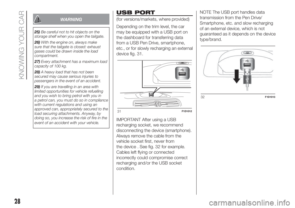
Depending on the trim level, the car
may be equipped with a USB port on
the dashboard for transferring data
from a USB Pen Drive, smartphone,
etc., or for slowly recharging an external
device fig. 31.
IMPORTANT After using a USB
recharging socket, we recommend
disconnecting the device (smartphone).
Always remove the cable from the
vehicle socket first, never from
the device . See fig. 32 for example.
Cables left flying or connected
incorrectly could compromise correct
recharging and/or the USB socket
condition.NOTE The USB port handles data
transmission from the Pen Drive/
Smartphone, etc. and slow recharging
of an external device, which is not
guaranteed as it depends on the device
type/brand.
31F1D1012
32F1D1013
28
KNOWING YOUR CAR
Page 32 of 228
To remove the smartphone from the
docking station:
turn the ring nut A fig. 35 so that it
clicks into position
;
take out the smartphone by pressing
it down to open the gripping hand;
remove the smartphone from the
docking station and release it. The load
on the spring inside the docking station
will allow the gripping hand to close
after the phone has been removed.
7) 8) 9)
WARNING
7)When the vehicle is moving, the
smartphone must be used in the docking
station only in a horizontal position and
without any inclination (see fig. 36). Any
other position of the docking station is
allowed only with the vehicle stopped, with
the sole purpose of facilitating the insertion
of the smartphone in the station.
8)The maximum dimensions of the usable
smartphones are: 67 mm (width) and 11
mm (depth).
9)The maximum weight of smartphone
that can be installed is 180 g.
VERSION WITH LPG
SYSTEM
30) 31) 14)10) 11) 12) 13)
INTRODUCTION
The LPG version features two fuel
supply systems: one for petrol and one
for LPG.
Although the LPG system has
numerous safety features, it is advisable
to proceed as follows every time the
vehicle is not in use for a long period or
moved in an emergency as a result of
a breakdown or accident:
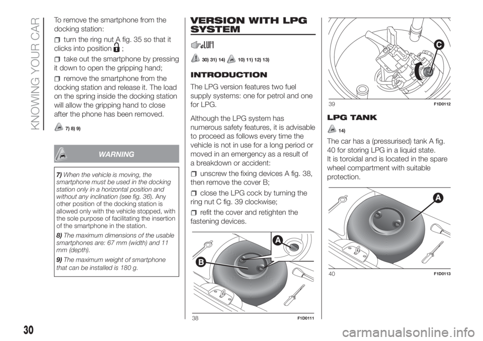
unscrew the fixing devices A fig. 38,
then remove the cover B;
close the LPG cock by turning the
ring nut C fig. 39 clockwise;
refit the cover and retighten the
fastening devices.LPG TANK
14)
The car has a (pressurised) tank A fig.
40 for storing LPG in a liquid state.
It is toroidal and is located in the spare
wheel compartment with suitable
protection.
38F1D0111
39F1D0112
40F1D0113
30
KNOWING YOUR CAR
Page 33 of 228
LPG tank certification
The LPG tank is certified in accordance
with the regulations in force.
In Italy, the tank has a life of 10 years
starting from the car registration date. If
the vehicle has been registered in a
country other than Italy, the duration
and the testing/inspection procedures
of the LPG tank can vary depending on
the national laws of that country. In all
case, when the time limit for your
country has expired, go to a Fiat Dealer
to have the tank replaced.
SELECTION OF
PETROL/LPG SUPPLY
TYPE
32)15) 16) 17)
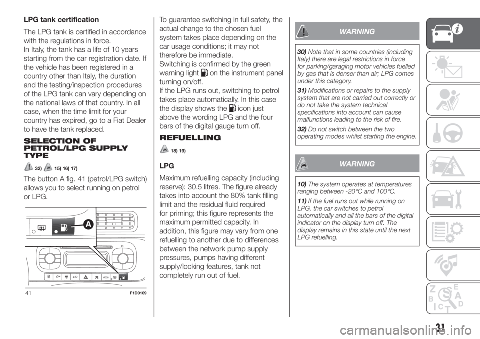
The button A fig. 41 (petrol/LPG switch)
allows you to select running on petrol
or LPG.To guarantee switching in full safety, the
actual change to the chosen fuel
system takes place depending on the
car usage conditions; it may not
therefore be immediate.
Switching is confirmed by the green
warning light
on the instrument panel
turning on/off.
If the LPG runs out, switching to petrol
takes place automatically. In this case
the display shows the
icon just
above the wording LPG and the four
bars of the digital gauge turn off.
REFUELLING
18) 19)
LPG
Maximum refuelling capacity (including
reserve): 30.5 litres. The figure already
takes into account the 80% tank filling
limit and the residual fluid required
for priming; this figure represents the
maximum permitted capacity. In
addition, this figure may vary from one
refuelling to another due to differences
between the network pump supply
pressures, pumps having different
supply/locking features, tank not
completely run out of fuel.
WARNING
30)Note that in some countries (including
Italy) there are legal restrictions in force
for parking/garaging motor vehicles fuelled
by gas that is denser than air; LPG comes
under this category.
31)Modifications or repairs to the supply
system that are not carried out correctly or
do not take the system technical
specifications into account can cause
malfunctions leading to the risk of fire.
32)Do not switch between the two
operating modes whilst starting the engine.
WARNING
10)The system operates at temperatures
ranging between -20°C and 100°C.
11)If the fuel runs out while running on
LPG, the car switches to petrol
automatically and all the bars of the digital
indicator on the display turn off. The
display remains in this state until the next
LPG refuelling.
41F1D0109
31