wind FIAT PUNTO 1997 176 / 1.G User Guide
[x] Cancel search | Manufacturer: FIAT, Model Year: 1997, Model line: PUNTO, Model: FIAT PUNTO 1997 176 / 1.GPages: 225, PDF Size: 18.54 MB
Page 150 of 225
5A«2 Starting and charging systems
Maintenance-free battery -charging Note: The following is intended as a guide only. Always refer to the manufacturer's recommendations (often printed on a label attached to the battery) before charging a battery. 13 This battery type takes considerably longer lo fully recharge than the standard type, the time taken being dependent on the extent of discharge, but it can take anything
up
to three days. 14 A constant voltage type charger is required, tooe set, when connected, to 13.9 to 14.9 votts wth a charger current below 25 amps. Using
mis
method, the battery should be usable within three hours, giving a voltage reading of 12.5 vofts. but this Is for a partially discharged battery and, as mentioned, full charging can
take
considerably longer. 15 If Ihe battery is to be charged from a fully discharged state {condition reading loss lhan 12.2 volts), have it recharged by your FIAT dealer or local automotive electrician, as Ihe charge rate is higher and constant super-vision during charging Is necessary.
3 Battery -removal and refitting
Note: Refer to Disconnecting the battery in ifte Reference Section of this manual before proceeding.
Removal 1 Slacken the clamp bolts and disconnect the ctamp from the battery negative (earth) terminal. 2 Remove the insulation cover (where fitted)
and
disconnect the positive terminal lead(s) in
Die same
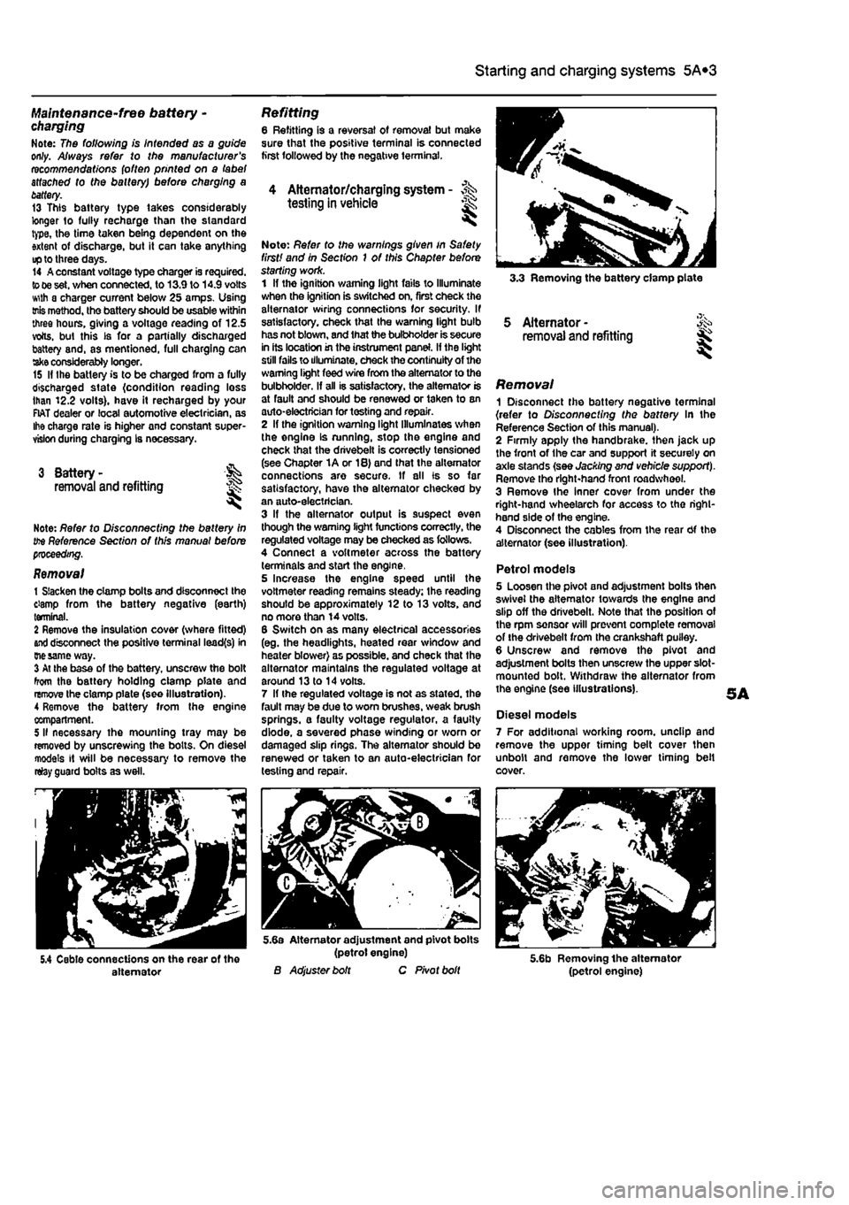
way. 3 At the base of the battery, unscrew the bolt from the battery holding clamp plate and remove the clamp plate (see Illustration). A Remove the battery from Ihe engine compartment. 5 II necessary the mounting tray may be removed by unscrewing the bolts. On diesel models it will be necessary to remove the relay guard bolts as well.
Refitting 6 Refitting is a reversal of removal but make sure that the positive terminal is connected first followed by the negative terminal.
4 Alternator/charging system - >%•> testing in vehicle
Note: Refer to the warnings given in Safety first! and in Section 1 of this Chapter before starting work. 1 If the ignition warning light fails to Illuminate when the ignition is switched on, first check the alternator wiring connections for security. If satisfactory, check that the warning light bulb has not blown, and that the bulbholder is secure in its location in the instrument panel. If the light still fails to illuminate, check the continuity of the warning light feed wire from the alternator to the bulbholder. If all is satisfactory, the alternator is at fault and should be renewed or taken to an auto-electrician for testing and repair. 2 If the ignition warning light Illuminates when the engine Is running, stop the engine and check that the drivebelt is correctly tensioned (see Chapter 1A or 18) and that the alternator connections are secure. If all is so far satisfactory, have the alternator checked by an auto-electrician. 3 If the alternator output is suspect even though the warning light functions correctly, the regulated voltage may be checked as follows. 4 Connect a voltmeter across the battery terminals and start the engine. 5 Increase the engine speed until the voltmeter reading remains steady; the reading should be approximately 12 to 13 volts, and no more than 14 volts. 6 Switch on as many electrical accessories (eg. the headlights, heated rear window and heater blower) as possible, and check that the alternator maintains the regulated voltage at around 13 to 14 volts. 7 If ihe regulated voltage is not as stated, the fault may be due to worn brushes, weak brush springs, e faulty voltage regulator, a faulty diode, a severed phase winding or worn or damaged slip rings. The alternator should be renewed or taken to an auto-electrician for testing and repair.
3.3 Removing the battery clamp plate
5 Alternator -removal and refitting
Removal 1 Disconnect the battery negative terminal {refer to Disconnecting the battery In the Reference Section of this manual). 2 Firmly apply the handbrake, then jack up the front of the car and support it securely on axle stands (see Jacking and vehicle support). Remove tho right-hand front roadwheel. 3 Remove Ihe Inner cover from under the right-hand wheelarch for access to tho right-hand side of the engine. 4 Disconnect the cables from the rear Of the alternator (see illustration).
Petrol models 5 Loosen the pivot and adjustment bolts then swivel the alternator towards the engine and slip off the drivebelt. Note that the position of the rpm sensor will prevent complete removal of the drivebelt from the crankshaft puiley. 6 Unscrew and remove the pivot and adjustment bolts then unscrew the upper slot-mounted bolt. Withdraw the alternator from the engine (see illustrations).
Diesel models 7 For additional working room, unclip and remove the upper timing belt cover then unbolt and remove the lower timing belt cover.
5.4 Cable connections on the rear of the alternator
5.6a Alternator adjustment and pivot bolts (petrol engine) B Adjuster bolt C Pivot bolt 5.6b Removing the alternator (petrol engine)
Page 153 of 225
5B*1
Chapters PartB:
Ignition system - petrol models
Contents
General information 1 Ignition system - testing 2 Ignriton HT coil - removal, testing and refitting 3 Ignition timing - checking and adjustment 4 Igrrtion system - check See Chapter 1A Spark plugs - renewal See Chapter 1A
Degrees of difficulty
Easy,
suitable for Falrty easy, sulabte Fafety difficult, suitable for competent Difficult, suitable for Very difficult, ^ novice with littie
1
for beginner with Fafety difficult, suitable for competent experienced DIY suitable for expert DIY or professional ^ expenence 1 some experience DIY mechanic mechanic *
suitable for expert DIY or professional ^
Specifications
General System type
firing order Ignition timing at Idle speed (non-adjustable, for reference onlyy. 6-valve engines: Single-point injection engine with manual transmission .... Single-point injection engine with automatic transmission.. Multi-point injection engine 16-valve engines
Ignition
coil winding resistance (at 20°C): Primary Secondary
Weber-Marelli static (distributorless), wasted spark Ignition system controlled by engine management ECU
1
-3-4-2 (No 1 cylinder at timing belt end of engine)
10® ± 3° BTDC 6° ± 3° STDC 13° ±3° BTDC 8° x 3° BTDC
0.495 to 0.605 ohms 6660 to 8140 Ohms
Page 154 of 225
5B*2 Ignition system - petrol models
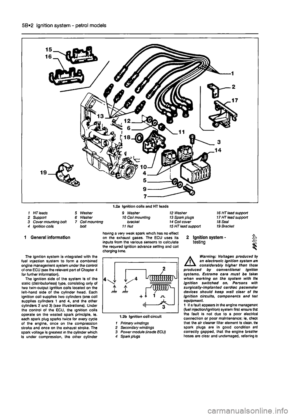
1 HT leads 2 Support 3 Cover mounting bdt 4 Ignition coifs
5 Washer 6 Washer 7 Coil mounting bolt
1.2s Ignition coils and HT leads 9 Washer 10 Coil mounting bracket
11
Nut
12 Waslrer 13 Spark plugs 14 Coll cover 15 HT lead support
16 HT lead support 17HTlead support 18 Seat Id Bracket
1 General information
The ignition system is integrated with the fuel injection system to form a combined engine management system under the control of one ECU (see the relevant part of Chapter 4 lor further Information). The Ignition side of the system is of the static (distributorless) type, consisting only of two twin-output Ignition coils located on the left-hand side of the cylinder head. Each ignition coil supplies two cylinders (one coll supplies cylinders 1 and 4, and the other cylinders 2 and 3) (see Illustrations). Under the control of the ECU, the ignition coils operate on the wasted spark principle, ie. each spark plug sparks twice for every cycle of the engine, once on the compression stroke and once on tho exhaust stroke. The spark voltage is greatest in the cylinder which Is under compression, the other cylinder
having a very weak spark which has no effect on the exhaust gases. The ECU uses Its Inputs from the various sensors to calculate the required ignition advance setting and coil chorging time.
1.2b Ignition coll circuit 1 Primary windings 2 Secondary windings 3 Power module
2 Ignition system -testing i
A
Warning: Voltages produced
by
an electronic Ignition system an considerably higher than (hose produced by conventional Ignition systems. Extreme care must be tak»n when working on tho system with thi Ignition switched on. Persons wilfl surgically-implanted cardiac pacemaker devices should keep well clear ot the ignition circuits, components and (oaf equipment 1 If a fault appears In the engine management (fuel injection/ignition) system first ensure that the fault is not due to a poor electrical connection or poor maintenance: ie, checK lhat the air cleaner filter element is clean, tht spark plugs are In good condition and correctly gapped, lhat the engine breather hoses are clear and undamaged, referring to
Page 155 of 225
Ignition system - petrol models 5B®3
Chapter 1A tor further information. Also check tnat tha accelerator cable is correctly adjusted
as
described in the relevant part of Chapter 4. If the engine is running very roughly, check the compression pressures and the valve clearances as descnbed In the relevant parts of Chapters 1 and 2. 2
H
these checks fall to reveal the cause of the problem, the vehicle should be taken to a suitably equipped Fiat dealer for testing. A wiring block connector Is Incorporated in the engine management circuit Into which a special electronic diagnostic tester can be plugged. The tester will locate the fault quickly and simply alleviating the need to test all the system components Individually which is a time consuming operation that carries a high risk of damaging the ECU. 3 The only Ignition system checks which can
oe
earned out by the home mechanic are those cescribed in Chapter 1A, relating to the spark plugs, and the ignition coll test descnbed In this Chapter. If necessary, the system wiring and wiring connectors can oe checked as descnbed in Chapter 12, Section 2, ensuring that the ECU wiring connector(s) have first
been
disconnected.
3 Ignition HT coil - ^ removal, testing and refitting
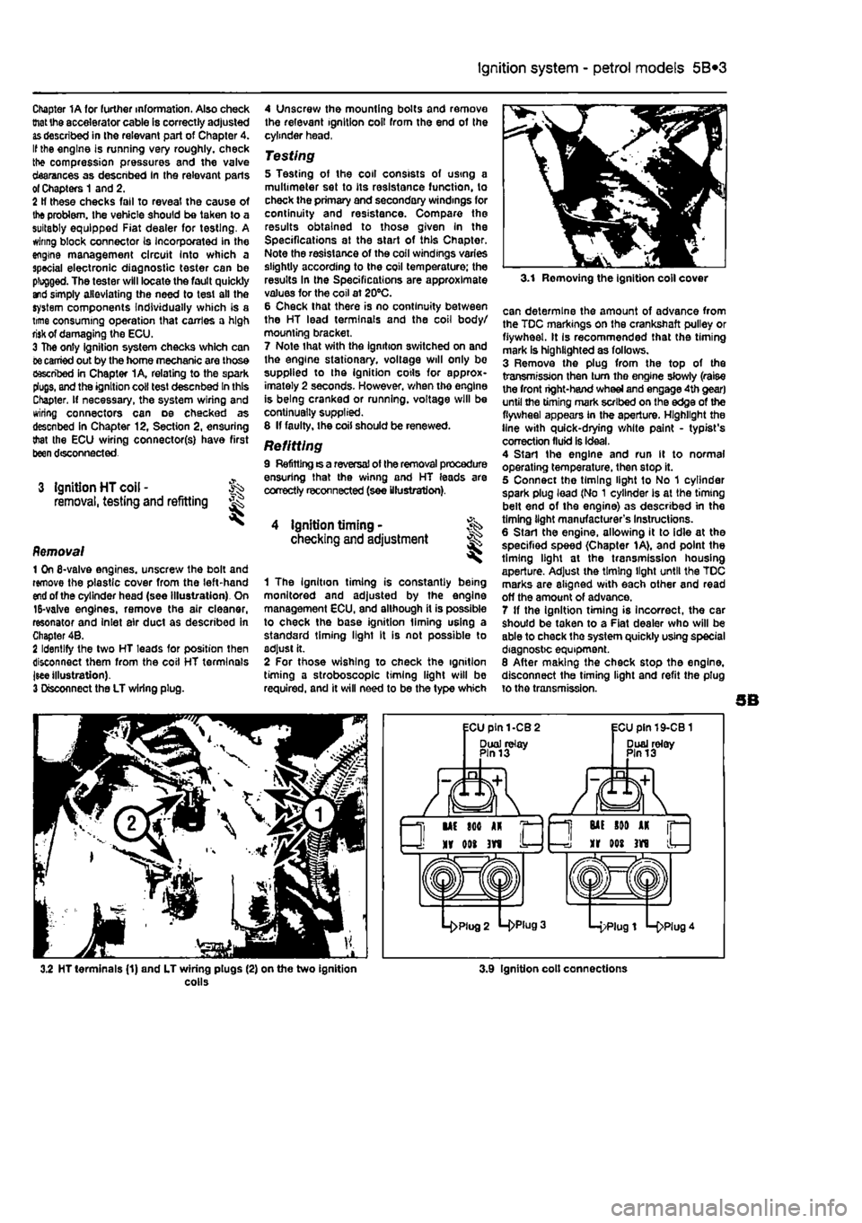
Removal 1 On 6-valve engines, unscrew the boll and remove the plastic cover from the left-hand
end
of the cylinder head (see Illustration). On 15-valve engines, remove the air cleaner, resonator and Inlet air duct as described in Chapter 4B. 2 Identify the two HT leads for position then disconnect them from the coil HT terminals jsee illustration). 3 Disconnect the LT wiring plug.
4 Unscrew the mounting bolts and remove the relevant ignition coil from the end of the cylinder head,
Testing 5 Testing of the coil consists of using a multimeter set to its resistance function, to check the primary and secondary windings for continuity and resistance. Compare the results obtained to those given In the Specifications at the start of this Chapter. Note the resistance of the coil windings varies slightly according to the coil temperature; the results In the Specifications are approximate values for the coil at 20°C. 6 Check that there is no continuity between the HT lead terminals and the coil body/ mourning bracket. 7 Note that with the ignition switched on and the engine stationary, voltage will only be supplied to the ignition cotls for approx-imately 2 seconds. However, when tho engine is being cranked or running, voltage will be continually supplied. 8 If faulty, the coil should be renewed.
Refitting 9 Refitting ts a reversal of the removal procedure ensuring that the winng and HT leads are correctly reconnected (see illustration).
4 ignition timing • checking and adjustment
1 The Ignition timing is constantly being monitored and adjusted by the engine management ECU, and although it is possible to check the base ignition liming using a standard timing light It is not possible to adjust it. 2 For those wishing to check the ignition timing a stroboscope timing light will be required, and it will need to be the type which
3.1 Removing the ignition coll cover
can determine the amount of advance from the TDC markings on the crankshaft pulley or flywheel. It Is recommended that the timing mark is highlighted as follows. 3 Remove the plug from the top of the transmission then turn tho engine slowly (raise the front right-hand wheel and engage 4th gear) until the timing mark scribed on the edge of the flywheel appears in the aperture. Highlight the line with quick-drying white paint - typist's correction fluid is ideal. 4 Start the engine and run It to normal operating temperature, then stop it. 5 Connect the timing light to No 1 cylinder spark plug lead (No 1 cylinder Is at the timing belt end of the engine) as described in the timing light manufacturer's Instructions. 6 Start the engine, allowing it to idle at the specified speed (Chapter 1A), and point the timing light at the transmission housing aperture. Adjust the timing light until the TDC marks are aligned with each other and read off the amount of advance. 7 If the ignition timing is incorrect, the car should be taken to a Fiat dealer who will be able to check the system quickly using special diagnostic equipment. 8 After making the check stop the engine, disconnect the timing light and refit the plug to the transmission.
3.2 HT terminals (1) and LT wiring plugs (2) on the two ignition colls 3.9 Ignition colt connections
Page 166 of 225
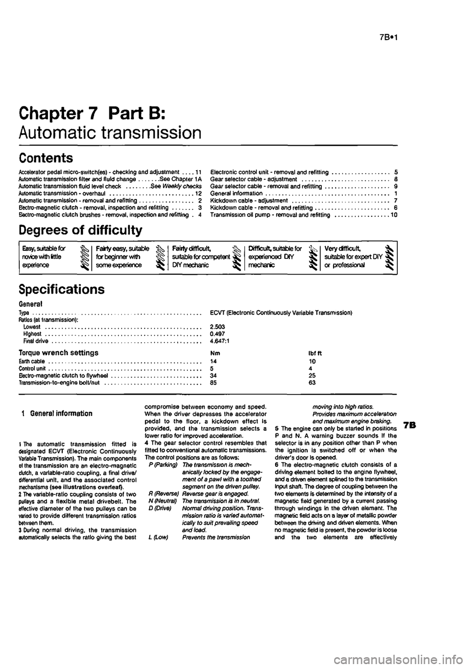
7B«1
Chapter 7 Part B:
Automatic transmission
Contents
Accelerator pedal micro-switch(es) - checking and adjustment II Automatic transmission filter and fluid change See Chapter 1A Automatic transmission fluid level check See Weekly checks Automatic transmission • overhaul 12 Automatic transmission • removal and refining 2 Bectro-magnetic clutch - removal, inspection and refitting 3 BectrO'fnagnetic clutch brushes- removal, inspection and refitting . 4
Electronic control unit - removal and refitting 5 Gear selector cable - adjustment 6 Gear selector cable - removal and refitting 9 General information 1 Kickdown cable - adjustment 7 Kickdown cable - removal and refitting 6 Transmission oil pump - removal and refitting 10
Degrees of difficulty
Easy,
suitable for novice
with
ittle experience ^
Party
easy,
suitable for beginner
with
^r someexperienoe ^
Faiily
difficult,
^ suitable
for
competent
DIY mechanic
^
Difficult, suitable
for fe, experienced DIY >8J mechanic
Verydfficult, ^
suitable
for
expert DIY
or professional ^
Specifications
General Type Ratios (at transmission): Lowest Highest Final drive
Torque wrench settings Esnh cable Control unit Sectro-magnetic clutch to flywheel Transmission-to-engine bolt/nut ..
ECVT (Electronic Continuously Variable Transmission)
2.503 0.497 4.647:1
Nm Ibftt 14 10 5 4 34 25 85 63
1 Genera) information
I The automatic transmission fitted is designated ECVT (Electronic Continuously Variable Transmission). The main components
01
the transmission are an electro-magnetic dutch, a variable-ratio coupling, a final drive/ differential unit, and the associated control mechanisms (see illustrations overleaf) 2 The variable-ratio coupling consists of two pulleys and a flexible metal drivebelt. The effective diameter of the two pulleys can be varied to provide different transmission ratios between them. 3 During normal driving, the transmission automatically selects the ratio giving the best
compromise between economy and speed. When the driver depresses the accelerator pedal to the floor, a kickdown effect is provided, and the transmission selects a lower ratio for improved acceleration. 4 The gear selector control resembles that fitted to conventional automatic transmissions. The control positions are as follows: P (Parking) The transmission is mech-anically locked by the engage-ment of a pawl with a toothed segment on the driven pulley. R (Reverse) Reverse gean's engaged, N (Neutral) The transmission is In neutral. D (Drive) Normal driving position. Trans-mission ratio is varied automat-ically to suit prevailing speed and load.
L (Low) Prevents the transmission
moving into high ratios. Provides maximum acceleration end maximum engine braking. 5 The engine can only be started In positions P and N. A warning buzzer sounds If the selector is in any position other than P when the ignition is switched off or when the driver's door is opened. 6 The electro-magnetic clutch consists of a driving element boiled to the engine flywheel, and a driven element spiined to the transmission Input shaft. The degree of coupling between the (wo elements Is determined by the intensity of a magnetic field generated by a current passing through windings in the driven element. The magnetic field acts on a layer of metallic powder between the driving and driven elements. When no magnetic field is present, the powder is loose and the two elements are effectively
Page 169 of 225
7B*4 Automatic transmission
2 Automatic transmission - ^ removal and refitting St
Removal 1 Select a solid, level surface to park the vehicle upon. Give yourself enough space to move around it easily. Apply the handbrake then jack up the front of the vehicle and support on axle stands (see Jacking and vehicle support). Remove both front wheels, 2 Remove the battery and mounting tray as described In Chapter 5A. 3 Remove the air cleaner and air inlet duct as described In Chapter 4A. 4 Disconnect the kickdown cable at the sector on the throttle housing and detach It from the mounting on the camshaft cover. Also release the cable from the support on the left-hand end of the cylinder head. 5 Disconnect the wiring connectors on the transmission. 6 Disconnect the fluid inlet and outlet Unas from the heat exchanger on top of the transmission. 7 Pull the fluid level dipstick from Its tube on the front of the transmission and tape over the top of the tube to prevent dirt entry. 8 Unscrew and remove the retaining pin and disconnect the speed selector cable from the top of the transmission. 9 Unscrew the upper bolt securing the starter motor to the transmission. 10 Unscrew the upper bolts securing the transmission to the engine. 11 Support the weight of the engine using a hoist attached to the engine lifting eyes, or alternatively UBO a trolley jack and block of wood beneath the engine, 12 Remove the screws and remove the front wheel arch liner from under the left-hand wheel arch. 13 Unscrew the nut securing the earth cablo to the transmission. 14 Using a punch drive out the roll pins securing both driveshafts to the final drive output shafts. 15 Unscrew and remove the bolts securing the left-hand swivel hub assembly to the front suspension strut, then separate the components and support the swivel hub on an axle stand. 16 Move the swivel hub assembly outwards and slide the inner end of the driveshaft from the splines on the transmission output shaft. Support the shaft away from the transmission to prevent damage to the gaiters. 17 Unscrew the lambdafoxygen sensor from the exhaust downpipe and position it In a safe place to prevent damage. 18 Unscrew ihe nuts securing the downpipe to Ihe exhaust manifold, then lower It and suppon on an axle stand. Recover the gasket. 19 Unscrew the knurled nut and disconnect the speedometer cable from the top of the final drive housing.
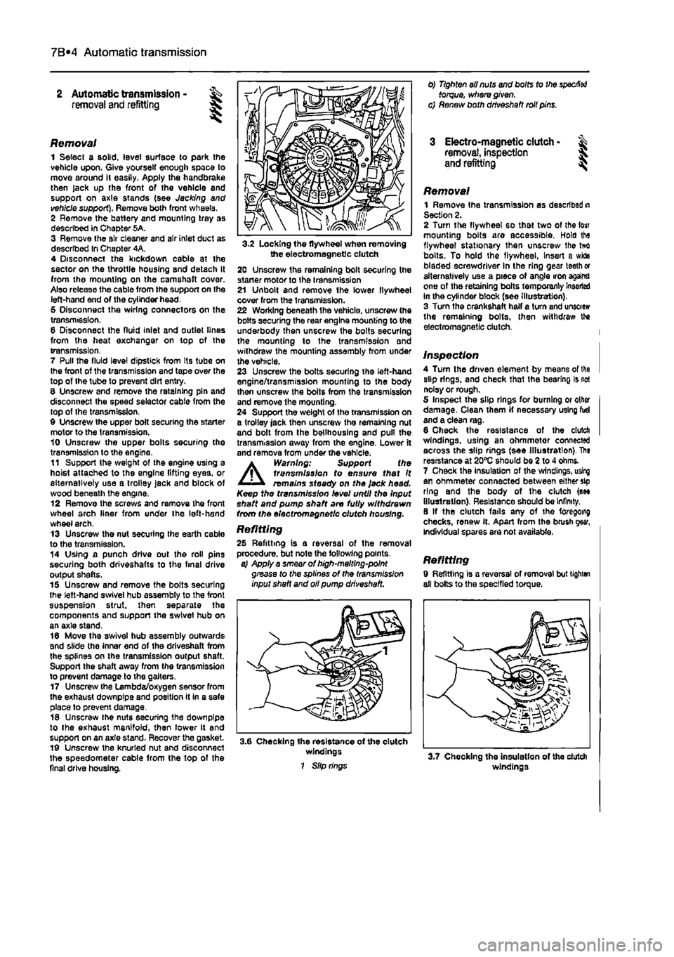
3-2 Locking the flywheel when removing the electromagnetic clutch 20 Unscrew the remaining bolt securing the staner motor to the transmission 21 Unbolt and remove Ihe lower flywheel cover from the transmission. 22 Working beneath the vehicle, unscrew the bolts securing the rear engine mounting to the underbody then unscrew the bolts securing the mounting lo the transmission and withdraw the mounting assembly from under the vehicle. 23 Unscrew the bolts securing the left-hand engine/transmission mounting to the body thon unscrew the bolts from the transmission and remove the mounting. 24 Support the weight of the transmission on a trolley jack then unscrew the remaining nut and bolt from the bellhouslng and pull the transmission away from the engine. Lower it and remove from under the vehicle.
A
Warning: Support the transmission to ensure that It remains steady on the Jack head. Keep the transmission level until the Input shaft and pump shaft are fully withdrawn from the electromagnetic clutch housing.
Refitting 25 Refitting is a reversal of the removal procedure, but note the following points. a} Apply a smear of high-melting-point grease to the splines of the transmission input shaft and oil pump driveshaft.
3.6 Checking the resistance of the clutch windings 1 Slip rings
0) Tighten all nuts and bolts to the
specified
torque, where given, c) Renew both driveshaft roll pins.
3 Electro-magnetic clutch • & removal, inspection 5. and refitting ^
Removal 1 Remove Ihe transmission as described n Section 2. 2 Turn the flywheel so that two of the lour mounting bolts are accessible, Hold tha flywheel stationary then unscrew Ihe tvrt bolts. To hold the flywheel, Insert a wida bladed screwdriver In the ring gear teeth or alternatively use a piece of angle iron against one of the retaining bolts temporarily Inserted in the cylinder block (see illustration). 3 Turn the crankshaft half a turn and unscrew the remaining bolts, then withdraw the electromagnetic clutch.
Inspection 4 Turn the driven element by means of tha slip rings, and check that the bearing is not noisy or rough. 5 Inspect the slip rings for burning or other damage. Clean them if necessary using fid and a clean rag. 6 Check the resistance of the clutch windings, using an ohmmetor connected across the slip rings (see Illustration). The resistance at 20*0 should be 2 to 4 ohms. 7 Check the Insulation of the windings, using an ohmmeter connected between either sip ring and the body of the clutch (see illustration). Resistance should be Infinity. 8 If the clutch fails any of the foregoing checks, renew it. Apart from the brush gear, Individual spares are not available.
Refitting 9 Refitting is a reversal of removal but tighten all bolts to the specified torque.
windings
Page 190 of 225
Suspension and steering 10*2
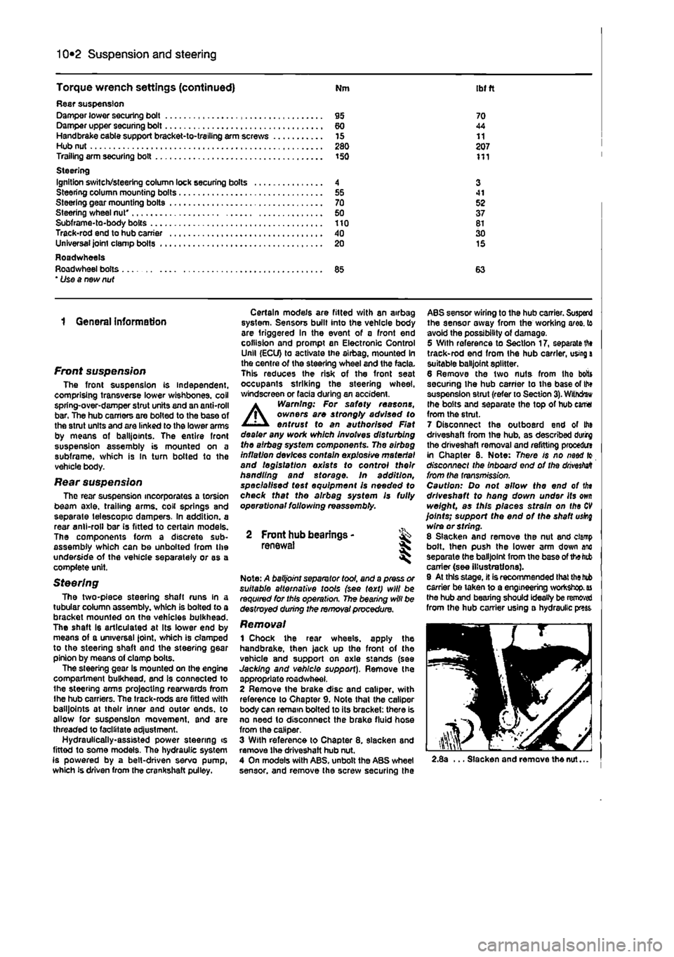
Torque wrench settings (continued) Nm ibt ft Rasr suspension Damper lower securing bolt 95 70 Damper upper securing bolt 60 44 Handbrake cable support bracket-to-trailing arm screws 15 11 Hub nut 280 207 Trailing arm securing bolt 150 111 Steering Ignition switch/steering column lock securing bolts 4 3 Steering column mounting bolts 55 41 Steering gear mounting bolts 70 52 Steering wheel nut' 50 37 Subframe-to-body bolts 110 81 Track-rod end to hub carrier 40 30 Unlversaijointclampbolts 20 15 Roadwheels Roadwheel bolts 85 63 * Use a new nut
1 General information
Front suspension The front suspension is independent, comprising transverse lower wishbones, coil spring-over-damper strut units and an anti-roll bar. The hub carriors are bolted to the base of the stmt units and are linked to the lower arms by means ot balliotnts. The entire front suspension assembly is mounted on a subframe, which is In turn botted to the vehicle body.
Rear suspension The rear suspension incorporates a torsion beam axle, trailing arms, coil springs and separate telescopic dampers. In addition, a rear anil-roll bar is fitted to certain models. The components form a discrete sub-assembly which can be unboiled from the underside of the vehicle separately or as a complete unit.
Steering The two-piece steering shaft runs in a tubular column assembly, which is bolted to a bracket mounted on the vehicles bulkhead. The shaft Is articulated at its lower end by means of a universal Joint, which is clamped to the steering shaft and the steering gear pinion by moans of clamp bolts. The steering gear is mounted on the engine compartment bulkhead, and is connected to the steering arms projecting rearwards from Ihe hub carriers. The track-rods are fitted with balljoints at their inner and outer ends, to allow for suspension movement, and are threaded to facilitate ad|ustment. Hydrauiically-assisted power steering ts fittod to some models. The hydraulic system is powered by a belt-driven servo pump, which is driven from the crankshaft pulley.
Certain models are fitted with an airbag system. Sensors built into the vehicle body are triggered in the event of a front end collision and prompt an Electronic Control Unll (ECU) to activate the airbag, mounted In the centre of the steering wheel and the facia. This reduces the risk of the front seat occupants striking the steering wheel, windscreen or facia during an accident.
A
Warning: For safety reasons, owners are strongty advised to entrust to an authorised Flat dealer any work which involves disturbing the airbag system components. The airbag inflation devices contain explosive material and legislation exists to control their handling and storage, in addition, specialised test equipment Is needed to check that the airbag system Is fully operational following reassembly.
2 Front hub bearings -renewal *
Note: A balljoint separator tool, and a press or suitable alternative tools (see text) will be required for this operation. The bearing will be destroyed during the removal procedure.
Removal 1 Chock the rear wheels, apply the handbrake, then jack up the front of the vehicle and support on axle stands (see Jacking and vehicle support). Remove the appropriate roadwheel. 2 Remove the brake disc and caliper, with reference to Chapter 9. Note that the caliper body can remain bolted to its bracket: there is no need lo disconnect the brake fluid hose from the caliper. 3 With reference to Chapter 8. slacken and remove the driveshaft hub nut. 4 On models with ABS, unbolt the ABS wheel sensor, and remove the screw securing the
ABS sensor wiring to the hub carrier. Suspend the sensor away from the working ares, to avoid the possibility of damage. 5 With reference to Section 17, separate
th»
track-rod end from the hub carrier, using
a
suitable balljoint splitter. 6 Remove the two nuts from tho botts securing Ihe hub carrier to the base of th» suspension strut (refer to Section
3).
Withdrew the bolts and separate the top of hub earrtt from the strut. 7 Disconnect the outboard end of Ito driveshaft from the hub, as described durirg the driveshaft removal and refitting procedm in Chapter 8. Note: There is no naod fo disconnect the Inboard end of the
drivestett
from the transmission. Caution: Do not allow the end of tin driveshaft to hang down under its
own
weight, as this places strain on the
CV
joints; support the end of the shaft uskg wire or string. 8 Slacken and remove the nut and clamp bolt, then push the lower arm down anc separate the balljoint from the base of the tab carrier (see illustrations). 9 At this stage, it is recommended that
the bub
carrier be taken to a engineering workshop,
as
the hub and bearing should ideally be removed from the hub carrier using a hydraulic press
2.8a ... Slacken and remove the nut...
Page 193 of 225
Suspension and steering 10*5
3,9s Withdraw the coll spring, complete with the compressors ... 3.9b ... then withdraw the dust cover and bump rubber 3.9c Fully dismantled strut
10 With the strut assembly now dismantled, examine all the components tor wear, damage or deformation. Check the rubber com-ponents for deterioration. Renew any of the components as necessary. 11 Examine tho damper for signs of fluid teakage. Check the damper rod for signs of pitting along its entire length, and check the stjul body for signs of damage. White holding fc
in an
upright position, test the operation of
Ihe
stmt by moving Ihe damper rod through a fut stroke, and then through short strokes of
SO
to 100 mm. In both cases, the resistance Id should be smooth and continuous. If the resistance is jerky, or uneven, or if there is any wsible sign of wear or damage to the strut, renewal is necessary. Note that the damper cannot be renewed independently, and if leakage, damage or corrosion Is evident, the complete strut/damper assembly must be renewed {in which case, the spring, upper mounting components, bushes, and associated components can be transferred to
Ihe
new strut). 12 If any doubt exists about the condition of
Ihe
coil spring, carefully remove the spring compressors, and check the spring for distortion and signs of cracking. Renew the spring if it is damaged or distorted, or if there isany doubt about its condition. a Warning: Coil springs are /j\ classified by their height when '
11
• undor load • this Is indicatod by a
coloured
paint marking on the side of the
coll windings (either green or yellow). All coll springs fitted to tho vehicle must be of the same classification to ensure the correct ride height. 13 Clamp the strut body in a vice, as dunng dismantling, then refit the lower spring seat rubber (where fitted), dust cover and bump rubber. 14 Ensure that the coil spring is compressed sufficiently to enable the upper mounting components to be fitted, then fit the spring over the damper rod. ensuring that the lower end of the spring is correctly located In the recess on the lower spring seat (soe illustration). 15 Refit the upper spring seat and upper mounting plate ensuring that the top end of
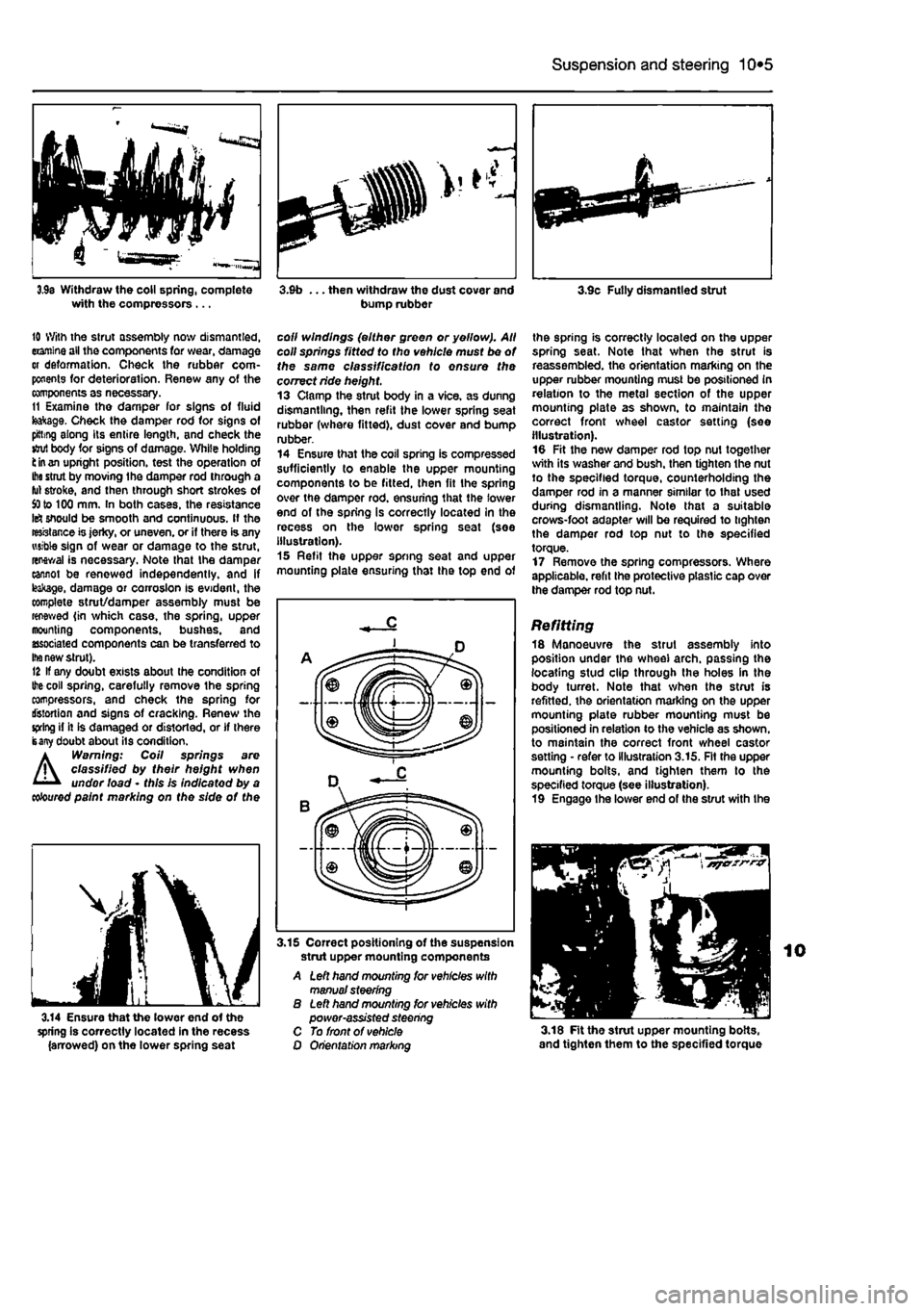
the spring is correctly located on the upper spring seat. Note that when the strut is reassembled, the orientation marking on the upper rubber mounting must be positioned in relation to the metal section of the upper mounting plate as shown, to maintain the correct front wheel castor setting (see illustration). 10 Fit the new damper rod top nut together with its washer and bush, then tighten the nut to the specified torque, counterholding the damper rod in a manner similar to that used during dismantling. Note that a suitable crows-foot adapter will be required to tighten the damper rod top nut to the specified torque. 17 Remove the spring compressors. Where applicable, refit the protective plastic cap over the damper rod top nut.
Refitting 18 Manoeuvre the strut assembly into position under the wheel arch, passing the locating stud clip through the holes in the body turret. Note that when the strut is refitted, the orientation marking on the upper mounting plate rubber mounting must be positioned in relation to the vehicle as shown, to maintain the correct front wheel castor setting • refer to illustration 3.15. Fit the upper mounting bolts, and tighten them to the specified torque (see illustration). 19 Engage Ihe lower end of the strut with the
3.14 Ensure that the lower end of the spring is correctly located in the recess (arrowed) on the lower spring seat
3.15 Correct positioning of the suspension strut upper mounting components A Left hand mounting for vehicles with manual steering B Left hand mounting tor vehicles with power-assisted steering C To front of vehicle O Orientation marking 3.18 Fit the strut upper mounting bolts, and tighten them to the specified torque
Page 202 of 225
10*1
Chapter 11
Bodywork and fittings
Contents
Bonnet • removal and refitting 11 Bonnet lock components - removal and refitting 12 Bonnet release cable - removal and refitting 13 Door - removal and refitting 15 Door handle and lock components • removal and refitting 16 Door inner trim panel • removal and refitting 14 Electric window components • removal and refitting 18 Exterior mirror components - removal and refitting 17 Facia - removal and refitting 19 Front bumper • removal and refitting 6
General Information 1 Maintenance - bodywork and underframe 2 Maintenance - upholstery and carpets 3 Major body damage - repair 5 Minor body damage - repair 4 Rear bumper - removal and refitting 7 Seats • removal and refitting 20 Tailgate - removal and refitting 8 Tailgate lock components - removal and refitting 10 Tailgate strut - removal and refitting 9
Degrees of difficulty
Easy, suitable for
novice with littie experience ^
Fairly
easy,
suitable ^ for beginner with ^
some
experience
Fairty difficult,
^
suitable
fcr competent
DIY
mechanic ^
Difficult,
suitable (or
^ experienced DIY »R mechanic ^
Very difficult,
^
suitable
for
expert CHY
or professional ^
Specifications
! Torque wrench settings Nm ibf ft Bonnet-to-hinge botts 8 6 Door hinge-to-body bolts 35 26
1 Genera! information
The bodyshell is composed of pressed-steel sections which are welded together, although some use of structural adhesives is made. In addition, the front wings are bolted i on. ' The bonnet, door and some other panels I vulnerable to corrosion are fabricated from zinc-coated metal. A coating of anti-chip primer, applied prior to paint spraying I provides further protection. Extensive use is made of plastic materials. ' mainly In the Interior, but also in exterior components. The outer sections of the front l and rear bumpers are injection-moulded from
a
synthetic material which is very strong, and yet light. Plastic components such as wheel | arch liners are fitted to the underside of the vehicle, to improve Ihe body's resistance to I corrosion.
2 Maintenance - ^ bodywork and underframe ||
The general condition of a vehicle's bodywork is the one thing that significantly affects its value. Maintenance is easy, but needs to be regular. Neglect, particularly after minor damage, can lead quickly to further deterioration and costly repair bills. It is important also to keep watch on those parts of the vehicle not immediately visible, for instance the underside, inside all the wheel arches, and the lower part of the engine compartment. The basic maintenance routine for the bodywork is washing - preferably with a lot of water, from a hose. This will remove all the loose solids which may have stuck to the vehicle. It is important to flush these off in such a way as to prevent grit from scratching the finish. The wheel arches and underframe need washing in the same way, to remove any
accumulated mud. which will retain moisture and tend to encourage rust. Paradoxically enough, the best time to clean the underframe and wheel arches is in wet weather, when the mud is thoroughly wet and soft. In very wet weather, the underframe is usually cleaned of large accumulations automatically, and this is a good time for inspection. Periodically, except on vehicles with a wax-based underbody protective coating, it is a good idea to have the whole of the underframe of Ihe vehicle steam-cleaned, engine compartment included, so that a thorough inspection can be carried out to see what minor repairs and renovations are necessary. Steam-cleaning is available at many garages, and is necessary for the removal of the accumulation of oily grime, which sometimes is allowed to become thick In certain areas. If steam-cleaning facilities are
Page 203 of 225
11 *2 Bodywork and fittings
on vehicles with wax-based underbody protective coating, or the coating will be removed. Such vehicles should be inspected annually, preferably just prior lo Winter, when the underbody should be washed down, and any damage to the wax coating repaired. Ideally, a completely fresh coat should be applied. It would also be worth considering the use of such wax-based protection for injection into door panels, sills, box sections, etc, as an additional safeguard against rust damage, where such protection Is not provided by the vehicle manufacturer. After washing paintwork, wipe off with a chamois feather to give an unspotted clear finish. A coat of clear protective wax polish wilt give added protection against chemical pollutants in the air. If the paintwork sheen has duiled or oxidised, use a cleaner/polisher combination to restore the brilliance of the shine. This requires a little effort, but such dulling Is usually caused because regular washing has been neglected. Care needs to be taken with metallic paintwork, as special non-abrasive cleaner/polisher is required to avoid damage to the finish, Always check that the door and ventilator opening drain holes and pipes are completely clear, so that water can be drained out. Brightwork should be treated In the same way as paintwork. Windscreens and windows can be kept clear of the smeary film which often appears, by the use of proprietary glass cleaner. Nover use any form of wax or other body or chromium polish on glass.
Maintenance -upholstery and carpets
Mats and carpets should be brushed or vacuum-cleaned regularly, to keep them free of grit. If they are badly stained, remove them from the vehicle for scrubbing or sponging, and make quite sure they are dry before refitting. Seats and interior trim panels can be kept clean by wiping with a damp cloth. If they do become stained (which can be more apparent on light-coloured upholstery), use a little liquid detergent and a soft nail brush lo scour the grime out of the grain of the material. Do not forget to keep the headlining clean in the same way as the upholstery. When using liquid cleaners inside the vehicle, do not over-wet the surfaces being cleaned. Excessive damp could get Into the seams and padded interior, causing stains, offensive odours or even rot.
If the Inside of the vehicle gets wet accidentally, tt Is worthwhile taking some trouble to dry ft out property, particularly where carpets an involved. Do not leave oil or electric heaters inside the vehicle for this purpose.
4 Minor body damage -repair
Repairs of minor scratches In bodywork If the scratch Is very superficial, and does not penetrate to the metal of the bodywork, repair is very simple. Lightly rub the area of the scratch with a paintwork renovator, or a very fine cutting paste, to remove loose paint from the scratch, and to clear the surrounding bodywork of wax polish, Rinse the area with clean water. Apply touch-up paint to ihe scratch using a fine paint brush; continue to apply fine layers of paint until the surface of the paint In the scratch Is level with the surrounding paintwork. Allow Ihe new paint at least two weeks to harden, then blend it Into the surrounding paintwork by rubbing the scratch area with a paintwork renovator or a very fine cutting paste. Finally, apply wax polish. Where the scratch has penetrated right through to the metal of the bodywork, causing the metal to rust, a different repair technique Is required. Remove any loose rust from the bottom of the scratch with a penknife, then apply rust-inhibiting paint to prevent the formation of rust in the future. Using a rubber or nylon applicator, fill the scratch with bodystopper paste. If required, this paste can be mixed with cellulose thinners to provide a very thin paste which is ideal for filling narrow scratches. Before the stopper-paste in Ihe scratch hardens, wrap a piece of smooth cotton rag around the top of a finger. Dip the finger in cellulose thinners, and quickly sweep it across the surface of the stopper-paste in the scratch: this will ensure that the surface of the stopper-paste is slightly hollowed. The scratch can now be painted over as described earlier In this Section.
Repairs of dents in bodywork When deop denting of the vehicle's bodywork has taken place, the first task is to put) the dent out. until the affected bodywork almost attains rts onginal shape. There is little polnl in trying to restore Ihe original shape completely, as the metal in the damaged area will have stretched on impact, and cannot be reshaped fully to its original contour. It Is better to bring the level of the dent up to a point which is about 3 mm below the level of the surrounding bodywork. In cases where Ihe dent is very shallow anyway, It is not worth trying to pull it out at all. If the underside of the dent is accessible, it can be hammered out gently from behind, using a mallet with a wooden or plastic head, Whilst doing this, hold a suitable block of wood firmly against (he outside of Ihe panel, to absorb the impact from the hammer blows and thus prevent a large area of the bodywork from being 'belled-out".
Should the dent be In a section of (I* bodywork which has a double skin, or seme other factor making It Inaccessible from behind, a different technique is called for. Dull several small holes through the metal inside Ihe area - particularly in the deeper section. Then screw long self-tapping screws Into the holes, just sufficiently for them to gain a good purchase in the metal. Now the dent can be pulled out by pulling on the protruding heads of the screws with a pair of pliers. The next stage of the repair Is the removal of the paint from the damaged area, and from an inch or so of the surrounding 'sound' bodywork. This is accomplished most easily by using a wire brush or abrasive pad on a posver drill, although it can be done just as effectively by hand, using sheets of abrasive paper. To complete the preparation for filling, score the surface of the bare metal wflhi screwdriver or the tang of 8 file, or alternatively, drill small holes In the affected area. This will provide a really good 'key' for the filler paste. To complete the repair, see the Section on filling and respraying.
Repairs of rust holes or gashes in bodywork Remove all paint from the affected area, and from an inch or so of the surrounding 'sound' bodywork, using an abrasive pad
or a
wire brush on a power drill. If these are not available, a few sheets of abrasive paper wil do the job most effectively. With the paint removed, you will be able to judge the severity of the corrosion, and therefore decide whether to renew the whole panel (if this is possible) or to repair the affected area. New body panels are not as expansive as most people think, and it is often quicker and more satisfactory to fit a new panel than to attempt to repair large areas of corrosion. Remove all fittings from Ihe affected area, except those which will act as a guide to ttie original shape of the damaged bodywork (eg headlight shells etc). Then, using tin snips
or a
hacksaw blade, remove all loose metal snd any other metal badly affected by corrosion. Hammer the edges of the hole inwards, in order to create a slight depression for the filer paste. Wire-brush the affected area to remove tha powdery rust from the surface of the remaining metal. Paint Ihe affected area with rust-inhibiting paint, if the beck of the rusted area is accessible, treat this also. Before filling can take place, ft will be necessary to block the hole in some
way.
TNs can be achieved by the use of aluminium cr plastic mesh, or aluminium tape. Aluminium or plastic mesh, or glass-fibre matting, is probably the best material to use for a large hole. Cut a piece to tha approximate size and shape of tho hole to b« filled, then position it In the hole so that its edges are below the level of the surrounding bodywork. It can be retained in position by