wind FIAT PUNTO 1997 176 / 1.G Workshop Manual
[x] Cancel search | Manufacturer: FIAT, Model Year: 1997, Model line: PUNTO, Model: FIAT PUNTO 1997 176 / 1.GPages: 225, PDF Size: 18.54 MB
Page 8 of 225
Roadside repairs 0.7
I Jump starting will get you out of trouble, but you must correct | whatever made the battery go fiat in the first place. There are three possibilities:
t
The battery has been drained by repeated attempts to start, or by leaving the lights on.
2
The charging system (s not working property (alternator drivebelt slack or broken, alternator wiring fault or alternator Itself faulty).
3
The battery Itself is at fault (ehctrotyte low, or battery worn out).
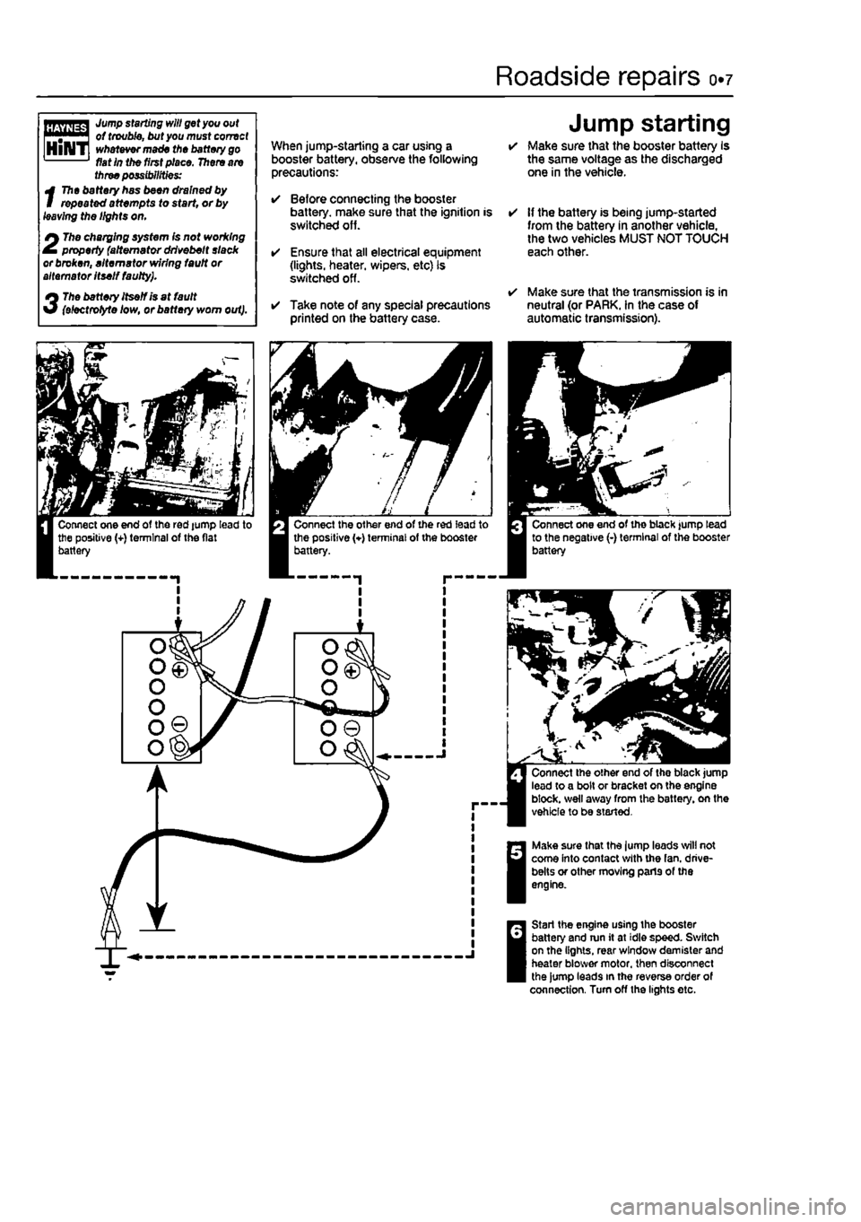
When jump-starling a car using a booster battery, observe the following precautions:
• Before connecting the booster battery, make sure that the ignition is switched off.
• Ensure that all electrical equipment (lights, heater, wipers, etc) is switched off.
• Take note of any special precautions printed on the battery case.
Jump starting • Make sure that the booster battery Is the same voltage as the discharged one in the vehicle.
• If the battery is being jump-started from the battery in another vehicle, the two vehicles MUST NOT TOUCH each other.
• Make sure that the transmission is in neutral (or PARK. In the case of automatic transmission).
Make sure that the lump leads will not come into contact with the fan. drive-belts or other moving parts of the engine.
Start the engine using the booster battery and run it at idle speed. Switch on the lights, rear window demister and heater blower motor, then disconnect the jump leads in the reverse order of connection. Turn off the lights etc.
Page 10 of 225
Roadside repairs 0.9
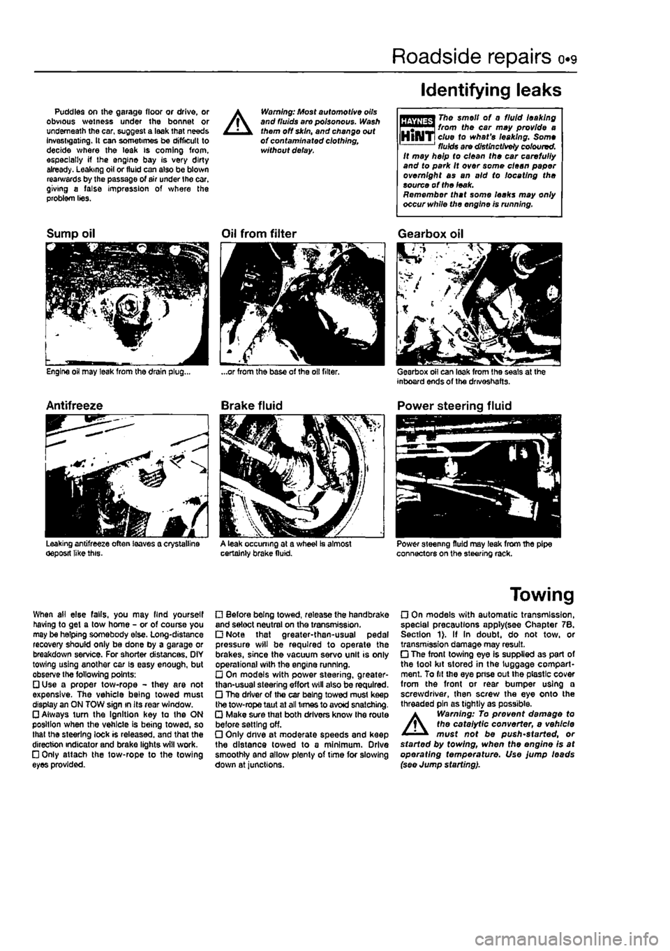
Puddles on the garage floor or drive, or obvious wetness under the bonnet or underneath the car, suggest a leak that needs Investigating. It can sometimes be difficult to decide where the leak is coming from, especially if the engine bay is very dirty already. Leaking oil or fluid can also be blown rearwards by the passage of air under the car, giving a false impression of where the problem lies.
A
Warning: Most automotive oils and fluids aro poisonous. Wash them off skin, and change out of contaminated clothing, without delay.
Identifying leaks
The smell of 0 fluid leaking from the car may provide a clue to what's leaking. Some fluids are distinctively coloured. It may help to clean the car carefully and to park It over some clean paper overnight as an aid to locating the source of the leak. Remember that some leaks may only occur while the engine is running.
Sump oil
Engine oil may leak from the drain plug...
Antifreeze
Leaking antifreeze often leaves a crystalline oeposit like this.
Oil from filter
A leak occurring at a wheel Is almost certainly brake fluid.
Gearbox oil
Gearbox oil can leak from the seals at the inboard ends of the drivoshafts.
Power steering fluid
Power steering fluid may leak from the pipe connectors on the steering rack.
When ail else falls, you may llnd yourself having to get a tow home - or of course you may be helping somebody else. Long-distance recovery should only be done by a garage or breakdown service. For shorter distances. OIY towing using another car is easy enough, but observe the following points: • Use a proper tow-rope - they are not expensive. The vehicle being towed must display an ON TOW sign in its rear window. • Always turn the Ignition key to the ON position when the vehicle is being towed, so that the steering lock is released, and that the direction indicator and brake lights will work. • Only attach the tow-rope to the towing eyes provided.
• Before being towed, release the handbrake and select neutral on the transmission. • Note that greater-then-usual pedal pressure will be required to operate the brakes, since the vacuum servo unit is only operational with the engine running. • On models with power steering, greater-than-usual steering effort will also be required. • The driver of the car being towed must keep the tow-rope taut at all times to avoid snatching. • Make sure that both drivers know the route before setting off. • Only dnve at moderate speeds and keep the distance towed to a minimum. Drive smoothly and allow plenty of time for slowing down at junctions.
Towing
• On models with automatic transmission, special precautions apply(see Chapter 7B. Section 1). If In doubt, do not tow, or transmission damage may result. • The front towing eye is supplied as part of the tool kit stored in the luggage compart-ment. To fit the eye pnse out the plastic cover from the front or rear bumper using a screwdriver, then screw the eye onto the threaded pin as tightly as possible.
A
Warning: To prevent damage to the catalytic converter, e vehicle must not be push'started, or started by towing, when the engine is at operating temperature. Use jump leads (see Jump starting).
Page 23 of 225
ia«4 Component location - petrol models
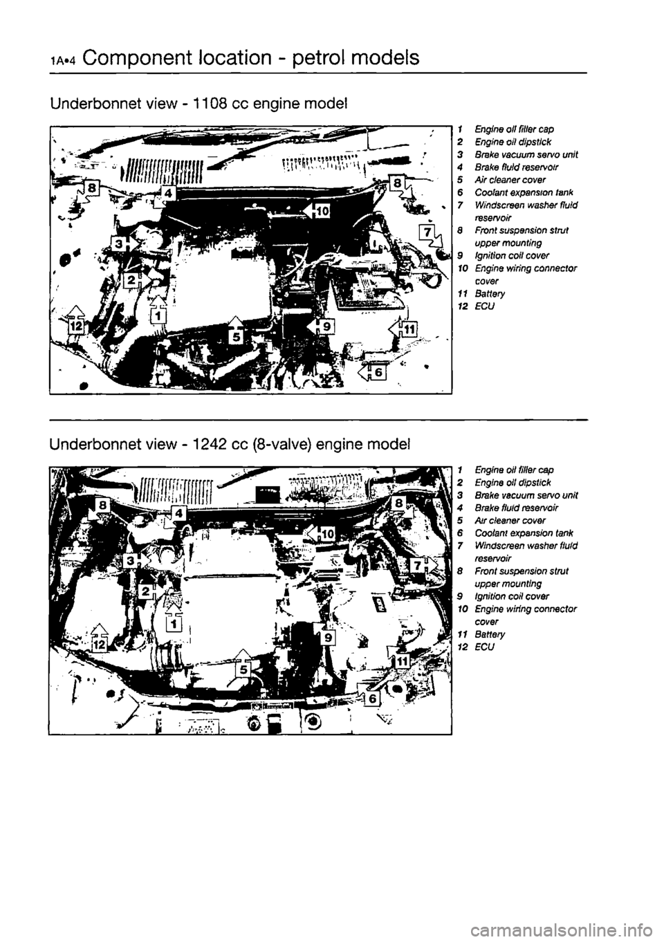
Underbonnet view -1108 cc engine model
1 Engine oil filler
cap
2 Engine oil dipstick 3 Brake vacuum servo unit 4 Brake fluid
reservoir
5 Air cleaner
cover
6 Coolant expansion lank 7 Windscreen washer fluid reservoir 8 Front suspension strut upper mounting 9 Ignition coil cover 10 Engine wiring connector cover 11 Battery 12 ECU
Underbonnet view - 1242 cc (8-valve) engine model
1 Engine oil tiller
cap
2 Engine oil dipstick 3 Brake vacuum servo unit 4 Brake fluid
reservoir
5 Air cleaner cover 6 Coo/ant expansion tank 7 Windscreen washer
fluid
reservoir 8 Front suspension strut upper mounting 9 Ignition coil cover 10 Engine wiring connector cover 11 Battery 12 ECU
Page 24 of 225
Component location - petrol models 1A.5
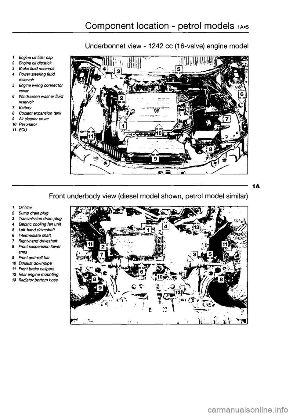
Underbonnet view - 1242 cc (16-valve) engine model
1
Engine
olt filler
cap
2
Engine
oil dipstick 3
Brake
fluid
reservoir
4
Power
steering fluid reservoir 5
Engine
wiring connector cover 6
Windscreen
washer
fluid
reservoir 7 Battery 8
Coolant
expansion
tank
9 Air cleaner
cover
10 Resonator 11 ECU
1
Oil filter
2
Sump
drain plug 3
Transmission
drain plug A
Electric
cooling Ian unit 5
Left-hand driveshaft
6
Intermediate shaft
7
Right-hand driveshaft
B
Front
suspension lower arms 9
Front
anti-roll
bar
10
Exhaust
downpipe 11
Front
brake calipers (2
Rear engine
mounting IS Radiator bottom hose
Front underbody view (diesel model shown, petrol model similar)
Page 28 of 225
Every 10 000 miles - petrol models ia.q
10 Pollen filter renewal
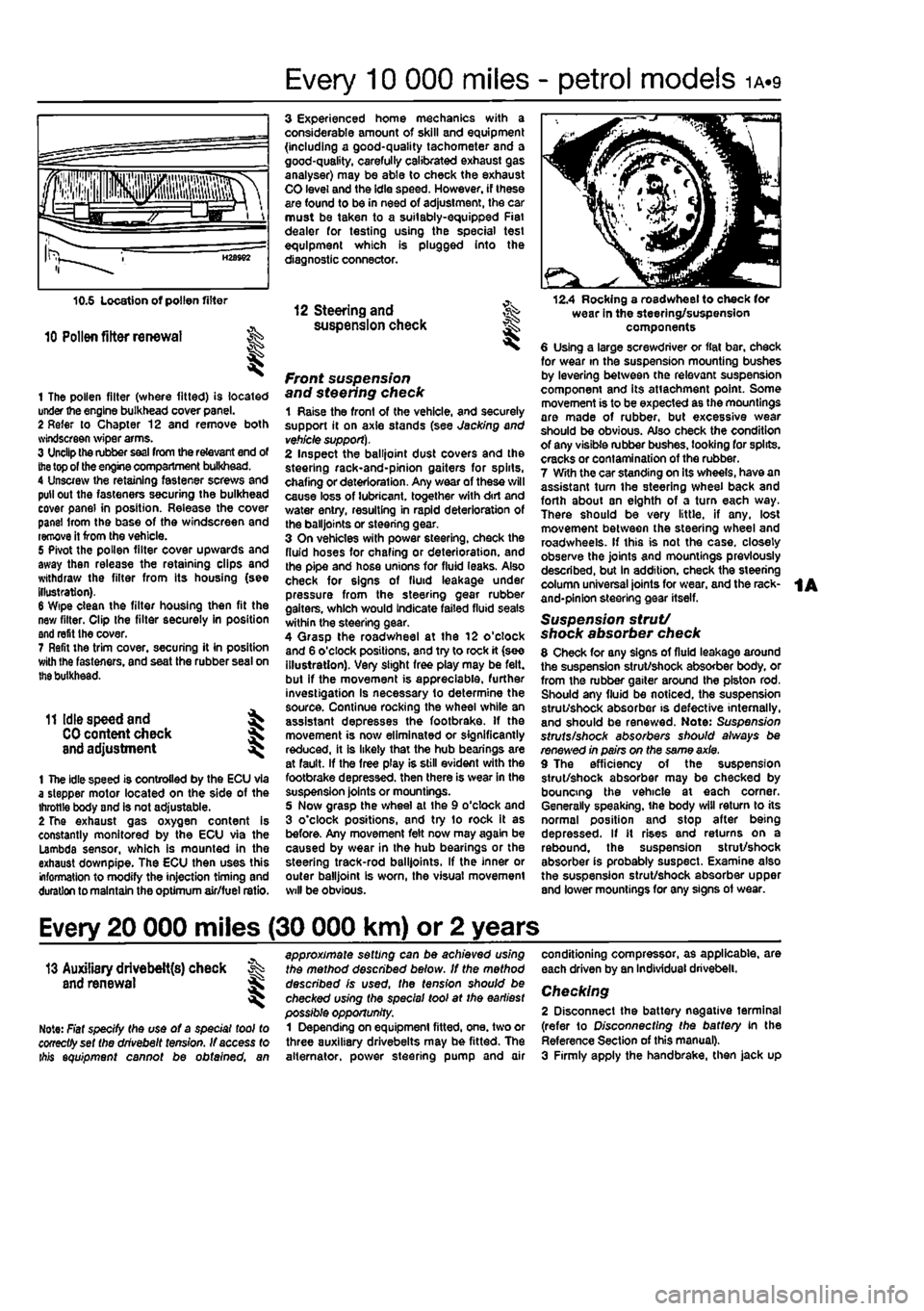
1 The pollen filter (where fitted) is located under the engine bulkhead cover panel. 2 Refer to Chapter 12 and remove both svindscreen wiper arms. 3 Unclip the rubber
seal
from the relevant end of
the
top of the engine compartment bulkhead. 4 Unscrew the retaining fastener screws and pull out the fasteners securing the bulkhead cover panel in position. Release the cover panel Irom the base of the windscreen and remove it from the vehicle. 5 Pivot the pollen filter cover upwards and away then release the retaining clips and withdraw the filter from its housing (see illustration). 6 Wipe clean the filter housing then fit the new filter. Clip the filter securely in position and refit the cover. 7 Refit the trim cover, securing it in position with Ihe fasteners, and seat the rubber seal on
the
bulkhead.
11 Idle speed and ^
CO
content check J and adjustment ^
1 The idle speed is controlled by the ECU via a stepper motor located on the side of the throttle body and is not adjustable. 2 The exhaust gas oxygen content is constantly monitored by the ECU via the Lambda sensor, which is mounted in the exhaust down pipe. The ECU then uses this information to modify the injection timing and duration to maintain the optimum air/fuel ratio.
3 Experienced home mechanics with a considerable amount of skill and equipment (including a good-quality tachometer and a good-quality, carefully calibrated exhaust gas analyser) may be able to check the exhaust CO level and the idle speed. However, if these are found to be in need of adjustment, the car must be taken to a suitably-equipped Fiat dealer for testing using the special test equipment which is plugged into the diagnostic connector.
12 Steering and ^ suspension check
front suspension and steering check 1 Raise the front of the vehicle, and securely support it on axle stands (see Jacking and
vehicle support).
2 Inspect the balljoint dust covers and the steehng rack-and-pinion gaiters for spirts, chafing or deterioration. Any wear of these will cause loss of lubricant, together with dirt and water entry, resulting in rapid deterioration of the balljoints or steering gear. 3 On vehicles with power steering, check the fluid hoses for chafing or deterioration, and the pipe and hose unions for fluid leaks. Also check for signs of fluid leakage under pressure from the steering gear rubber gaiters, which would indicate failed fluid seals within the steering gear. 4 Qrasp the roadwheel at the 12 o'clock and 6 o'clock positions, and try to rock it (see illustration). Very slight free play may be felt, but if the movement is appreciable, further investigation Is necessary to determine the source. Continue rocking the wheel while an assistant depresses the footbrake. If the movement is now eliminated or significantly reduced, it is likely that the hub bearings are at fault. If the free play is still evident with the footbrake depressed, then there is wear in the suspension joints or mountings. 5 Now grasp the wheel at the 9 o'clock and 3 o'clock positions, and try to rock it as before. Any movement felt now may again be caused by wear in the hub bearings or the steering track-rod balljoints. If the inner or outer balljoint is worn, the visual movement will be obvious.
12.4 Rocking a roadwheel to check for wear in the steering/suspension components 6 Using a large screwdriver or flat bar, check for wear in the suspension mounting bushes by levering between the relevant suspension component and its attachment point. Some movement is to be expected as the mountings are made of rubber, but excessive wear should be obvious. Also check the condition of any visible rubber bushes, looking for splits, cracks or contamination of the rubber. 7 With the car standing on its wheels, have an assistant tum the steering wheel back and forth about sn eighth of a turn each way. There should be very little, if any. lost movement between the steering wheel and roadwheels. If this is not the case, closely observe the joints and mountings previously described, but in addition, check the steering column universal joints for wear, and the rack-and-pinion steering gear itself.
Suspension strut/ shock absorber check 8 Check for any signs of fluid leakage around the suspension strut/shock absorber body, or from the rubber gaiter around the piston rod. Should any fluid be noticed, the suspension strut/shock absorber is defective internally, and should be renewed. Note: Suspension struts/shock absorbers should always be renewed in pairs on the same axle. 9 The efficiency of the suspension strut/shock absorber may be checked by bouncing the vehicle at each corner. Generally speaking, ihe body will return to its normal position and stop after being depressed. If it rises and returns on a rebound, the suspension strut/shock absorber is probably suspect. Examine also the suspension strut/shock absorber upper and lower mountings for any signs of wear.
Every 20 000 miles (30 000 km) or 2 years
13 Auxiliary drivebelt{s) check % and renewal ^
Note: Fiat specify the use of a special tool to cooectfyset the drivebelt tension. If access to ibis equipment cannot be obtained, an
approximate setting can be achieved using the method described below. If the method described is used, the tension should be checked using the special tool at the earliest possible opportunity. 1 Depending on equipment fitted, one. two or three auxiliary drivebelts may be fitted. The alternator, power steering pump and air
conditioning compressor, as applicable, are each driven by an Individual drivebelt.
Checking 2 Disconnect the battery negative terminal (refer to Disconnecting the battery in the Reference Section of this manual). 3 Firmly apply the handbrake, then jack up
Page 36 of 225
Every 2 years - petrol models ia.i?
check, and if necessary top-up, the level in the expansion tank. Refit the cap on completion. Antifreeze mixture 22 The antifreeze should always be renewed at the specified Intervals. This is necessary not only to maintain the antifreeze properties, but also to prevent corrosion which would otherwise occur as the corrosion inhibitors
beoome
progressively less effective. 23 Always use an ethylene-glycol based antifreeze which Is suitable for use In mixed-metal cooling systems, The quantity of antifreeze and levels of protection are
Indicated In
the Specifications. 24 8efore adding antifreeze, the cooling system should be completely drained, preferably flushed, and all hoses checked for condition and security. 25 After filling with antifreeze, a label should
be attached
to the expansion tank, stating the type and concentration of antifreeze used, and the date installed. Any subsequent lopping-up should be made with the same
type and
concentration of antifreeze. 26 Do not use engine antifreeze In the windscreen/tailgate washer system, as it will
cause damage to the vehicle paintwork. A screenwash additive should be added to the washer system in the quantities stated on the bottle.
34 Brake fluid renewal | I
A
Warning: Brake hydraulic fluid can harm your eyes and damage painted surfaces, so use extreme caution when handling and pouring H. Do not use fluid that has been standing open for some t/me, as it absorbs moisture from the air. excess moisture can cause a dangerous ioss of braking effectiveness. 1 The procedure is similar to that for the bleeding of the hydraulic system as described in Chapter 9, except that the brake fluid reservoir should be emptied by siphoning, using a clean poultry baster or similar before starting, and allowance should be made for the old fluid to be expelled when bleeding a section of the circuit. 2 Working as described In Chapter 9, open the first bleed screw in the sequence, and
pump the brake pedal gently until nearly all the old fluid has bsen emptied from the master cylinder reservoir.
Old hydraulic fluid Is Invariably much darker In colour than the new, making It easy to distinguish the two.
3 Top-up to the MAX level with new fluid, and continue pumping until onty the new fluid remans in the reservoir, and new fluid can be seen emerging from the bleed screw. Tighten the screw, and top the reservoir level up to the MAX level line. 4 Work through all the remaining bleed screws in the sequence until new fluid can be seen at all of them. Be careful to keep the master cylinder reservoir topped-up to above the MIN level et all times, or air may enter the system and greatly increase the length of the task. 5 When the operation Is complete, check that all bleed screws are securely tightened, and that their dust caps are refitted. Wash off all traces of spilt fluid, and recheck the master cylinder reservoir fluid level. 6 Check the operation of the brakes before taking the car on the road.
1A
Page 40 of 225
ib-4 Component location - diesel models
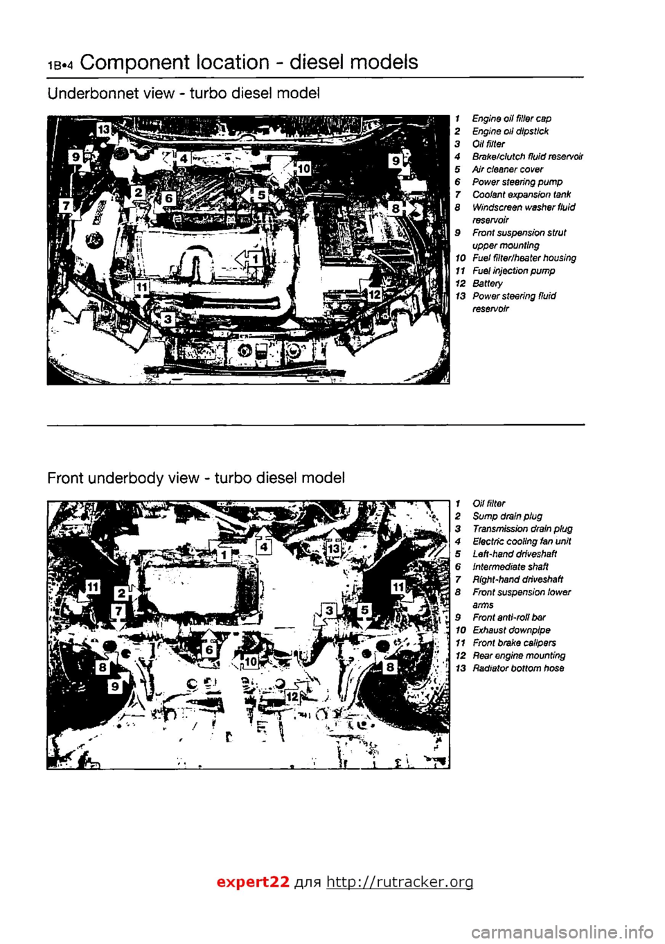
Underbonnet view - turbo diesel model
1 Engine oil filter
cap
2 Engine oil dipstick 3 Oil
tilter
4 Brake/clutch fluid
reservoir
5 Air cleaner
cover
6 Power steering pump 7 Coolant expansion
tank
8 Windscreen washer
fluid
reservoir 9 Front suspension strut upper mounting 10 Fuel filter/heater
housing
11
Fuel
injection pump 12 Battery 13 Power steering fluid reservoir
Front underbody view - turbo diesel model
1 Oil
fitter
2 Sump drain plug 3 Transmission drain plug 4 Electric cooling fan unit 5 Left-hand
driveshaft
6 Intermediate
shaft
7 Bight-hand
driveshaft
8 Front suspension lower arms 9 Front anti-roll
bar
10 Exhaust downpipe 11 Front brake calipers 12
Rear
engine mounting 13 Radiator bottom hose
expert22 fl/ia http://rutracker.org
Page 45 of 225
Every 10 000 miles - diesel models ib«9
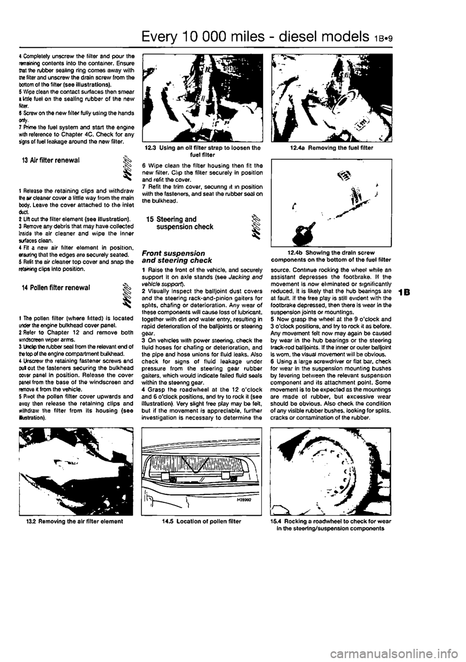
4 Completely unscrew the filter and pour the remaining contents into the container. Ensure (hat the rubber sealing ring comes away with
me
fitter and unscrew the drain screw from the
bottom
of tho filter (see illustrations). 5 Wipe clean the contact surfaces then smear
a
ittfe fuel on the sealing rubber of the new Nter. 6 Screw on the new filter fully using the hands orty. 7 Prime the fuel system and start the engine wth reference to Chapter 4C. Check for any signs of fuel leakage around the new filter.
13 Air fitter renewal
t Release the retaining clips and withdraw
Ihe
air cleaner cover a little way from the main body. Leave the cover attached to the inlet duct. 2 Lift out the filter element (see illustration). 3 Remove any debris that may have collected Inside the air cleaner and wipe the Inner surfaces clean. 4 Fit a new air filter element in position, ensuring that the edges are securely seated. 6 Refit the air cleaner top cover and snap the retaining clips into position.
14 Pollen filter renewal
t
1 The pollen filter (where fitted) Is located under the engine bulkhead cover pane). 2 Refer to Chapter 12 and remove both windscreen wiper arms. 3 Undp tho rubber seal from the relevant end of
the top
of the engine compartment bulkhead. 4 Unscrew the retaining fastener screws and Duiout the fasteners securing the bulkhead eovar panel in position. Release the cover panel from the base of the windscreen and remove it from the vehicle. 5 Pivot the pollen filter cover upwards and away then release the retaining clips and withdraw the filter from Its housing (see lustration).
12.3 Using an olt filter strap to loosen the fuel filter 6 Wipe clean the filter housing then fit the new filter, Clip the filter securely In position and refit the cover. 7 Refit the trim cover, secunng it >n position with the fasteners, and seat Ihe rubber seal on the bulkhead.
12.4a Removing the fuel filter
15 Steering and §S> suspension check ^
Front suspension and steering check 1 Raise the front of the vehicle, and securely support it on axle stands (see Jacking and vehicle support). 2 Visually Inspect the balljoint dust covers and the steering rack-and-pinion gaiters for splits, chafing or deterioration. Any wear of Ihese components will cause loss of lubricant, together with dirt and water entry, resulting in rapid deterioration of the balljoints or steering gear. 3 On vehicles with power steering, check the fluid hoses for chafing or deterioration, and the pipe and hose unions for fluid leaks. Also check for signs of fluid leakage under pressure from the steering gear rubber gaiters, which would indicate failed fluid seals within the steenng gear. 4 Grasp the roadwheel at the 12 o'clock and 6 o'clock positions, and try to rock it (see illustration). Very slight free play may be felt, but if the movement is appreciable, further investigation is necessary to determine the
fplllll iHpjiiisisps fa^aJw a LJgr >
H58B92
12.4b Showing the drain screw components on the bottom of the fuel filter source. Continue rocking the wheel while an assistant depresses the footbrake. If the movement Is now eliminated or significantly reduced, it is likely that the hub bearings are at fault. If the free ptay is still evident with the footbrake depressed, then there Is wear In the suspension joints or mountings. 5 Now grasp the wheel at the 9 o'clock and 3 o'clock positions, and try to rock it as before. Any movement felt now may again be caused by wear in the hub bearings or the steering track-rod balljoints. If the inner or outer balljoint Is worn, the visual movemont will be obvious. 6 Using a large screwdriver or flat bar. check for wear in the suspension mounting bushes by levering between the relevant suspension component and its attachment point. Some movement is to be expected as the mountings are made of rubber, but excessive wear should be obvious. Also check the condition of any visible rubber bushes, looking for splits, cracks or contamination of the rubber.
13.2 Removing the air filter element 14.5 Location of pollen filter 15.4 Rocking a roadwheel to check for wear in the steering/suspension components
Page 50 of 225
ib.14 Every 2 years - diesel models
Radiator flushing 7 To flush the radiator disconnect the top and bottom hoses and any other relevant hoses from the radiator, with reference to Chapter 3. 8 Insert a garden hose into the radiator top inlet. Direct a flow of dean water through the radiator, and continue Hushing until clean water emerges from the radiator bottom outlet. 9 II after a reasonable period, the water still does not run clear, the radiator can be flushed with a good proprietary cooling system cleaning agent. It is important that their manufacturer's instructions are followed carefully. If Ihe contamination is particularly bad, insert the hose in the radiator bottom outlet, and reverse-flush the radiator.
Engine flushing 10 To flush tho engine, remove the thermostat as described in Chapter 3. 11 With the bottom hose disconnected, direct a clean flow of water through the engine, and continue Hushing until clean water emerges from the radiator bottom hose. 12 On completion of flushing, refit the thermostat and reconnect the hose with reference to Chapter 3.
Cooling system filling 13 Before attempting to fill the cooling system, make sure that all hoses and clips are in good condition, and that the clips are tight. Note that an antifreeze mixture must be used all year round, to prevent corrosion of the engine components (see following sub* Section). 14 Remove the expansion tank filler cap. and fill the system by slowly pouring the coolant Into Ihe expansion tank to prevent airlocks from forming. Ensure that all bleed plugs/screws are open. 15 If the coolant is being renewed, begin by pouring in a couple of litres of water, followed by the correct quantity of antifreeze, then top* up with more water. 18 Once ihe level in the expansion tank starts to rise, squeeze the radiator top and bottom hoses to help expel any trapped air in
the system. Once all the air is expelled, top-up the coolant level to the MAX mark and refit the expansion tank cap. Close all bleed plugs. 17 Start Ihe engine and run il until it reaches normal operating temperature, then stop the engine and allow It to cool. 18 Check for leaks, particularly around disturbed components. Check the coolant level In the expansion tank, and top-up if necessary. Note that the system must be cold before an accurate level Is indicated In the expansion tank. If the expansion tank cap Is removed while the engine is still warm, cover the cap with a thick cloth, and unscrew the cap slowly to gradually relieve the system pressure (a hissing sound will normally be heard). Wait until any pressure remaining in the system Is released, then continue to turn the cap untH it can be removed.
Antifreeze mixture 19 The antifreeze should always be renewed at the specified intervals. This is necessary not only to maintain the antifreeze properties, but also to prevent corrosion which would otherwise occur as the corrosion Inhibitors become progressively less effective. 20 Always use an ethylene-glycol based antifreeze which is suitable for use in mixed-metal cooling systems. The quantity of antifreeze and levels of protection are indicated in the Specifications. 21 Before adding antifreeze, the cooling system should be complelely drained, preferably flushed, and all hoses checked for condition and security. 22 After filling with antifreeze, a label should be attached to the expansion tank, stating the type and concentration of antifreeze used, and the dale installed. Any subsequent topping-up should bs made with the same type and concentration of antifreeze. 23 Do not use engine antifreeze In the windscreen/tailgate washer system, as it will cause damage to the vehicle paintwork. A screenwash additive should be added to the washer system in the quantities stated on the bottle.
28 Brake fluid renewal
A
Warning: Brake hydraulic fluid can harm your eyas and damage painted surfaces, so use extreme caution when handling and pouring It. Do not use fluid that has been standing open for some time, as It absorbs moisture from the air. Excess moisture can causa a dangerous loss of braking effectiveness. 1 The procedure is similar to that for the bleeding of the hydraulic system as described In Chapter 9. except that the brake fluid reservoir should be emptied by siphoning, using a clean poultry baster or similar before starting, and allowance should be made for the old fluid to be expelled when bleeding a section of the circuit. 2 Working as described in Chapter 9, open Ihe first bleed screw in the sequence, and pump the brake pedal gently until nearly all the old fluid has been emptied from the master cylinder reservoir.
ffffTOgf Old hydraulic fluid Is
lifcjllitt*
Invariably much darker In [HINT] colour than the new, making /{easy to distinguish the two.
3 Top-up to the MAX level with new fluid, and continue pumping until only the new fluid remains in the reservoir, and new fluid can be seen emerging from (he bleed screw. Tighten the screw, and top the reservoir level up to Ihe MAX level line. 4 Work through all the remaining bleed screws In the sequence until new fluid can be seen al all of them. Be careful to keep the master cylinder reservoir topped-up 10 above the MIN level al all limes, or air may enter the system and greatly increase the length of the task. 5 When the operation is complete, check thai all bleed screws are securely tightened, and that their dust caps are refitted. Wash off ail traces of split fluid, and recheck the master cylinder reservoir fluid level. 6 Check the operation of the brakes before taking the car on the road,
Page 136 of 225
4C»1
Chapter 4 PartC:
Fuel system - diesel models
Contents
Accelerator cable • removal, refitting and adjustment 3 Air cleaner and inlet system • removal and refitting 2
AJr
cleaner filter element - renewal See Chapter IB Fuet filter renewal See Chapter 1B Fuel gauge sender unit • removal and refitting 10 Fuel injection pump • removal and refitting 5 Fuel injectors - testing, removal and refitting 9
Fuel
system • priming and bleeding 4
Fuel
tank - removal and refitting 11 General Information and precautions 1
Idle speed - checking and adjustment See Chapter 1B Injection timing • checking methods 6 injection timing {Bosch fuel Injection pump) • checking and adjustment 7 Injection timing (Lucas fuel Injection pump) - checking and adjustment 8 Inlet manifold - removal and refitting 12 Turbocharger - description and precautions 13 Turbocharger - examination and renovation 15 Turbocharger - removal and refitting 14
Degrees of difficulty
Easy,
suitable for novice
with Ittle
p experience sS^
Fairly easy, suitable (or beginner with some experience
Fairly tfifficuit, suitable
for
competent ^
DIY
mechanic
Difficult, suitable
for ^ experienced DIY jR mechanic ^
Very difficult, ^ sutable for expert
DIY
S or professional ^
Specifications
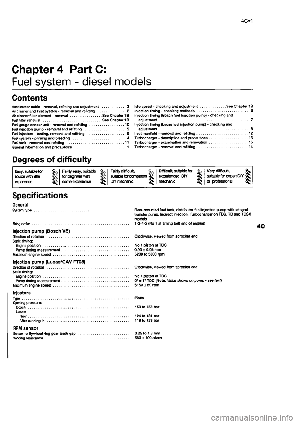
General System type
Firing order
Injection pump (Bosch VE) Direction of rotation Static timing: Engine position Pump timing measurement Maximum engine speed
Injection pump (Lucas/CAV FT08) Direction of rotation Static timing: Engine position Pump timing measurement Maximum engine speed
injectors Type Opening pressure: Bosch Lucas: New After running in
RPM sensor Sensor-to-flywheel ring gear teeth gap — Winding resistance
Rear-mounted fuel tank, distributor fuel injection pump with integral transfer pump. Indirect Injection, Turbocharger on TDS, TD and TDSX models 1-3-4-2 (No
1
at timing belt end of engine)
Clockwise, viewed from sprocket end
No
1
piston at TDC 0.93 ± 0.05 mm 5200 to 5300 rpm
Clockwise, viewed from sprocket end
No 1 piston at TDC 0° ± 1° TDC (Note: Value shown on pump - see text} 5150150 rpm
Pintle
150 to 158 bar
124 to
131
bar 116lo123 bar
0.25 to 1.3 mm 680* 100 ohms