key FIAT PUNTO 1998 176 / 1.G Workshop Manual
[x] Cancel search | Manufacturer: FIAT, Model Year: 1998, Model line: PUNTO, Model: FIAT PUNTO 1998 176 / 1.GPages: 225, PDF Size: 18.54 MB
Page 10 of 225
Roadside repairs 0.9
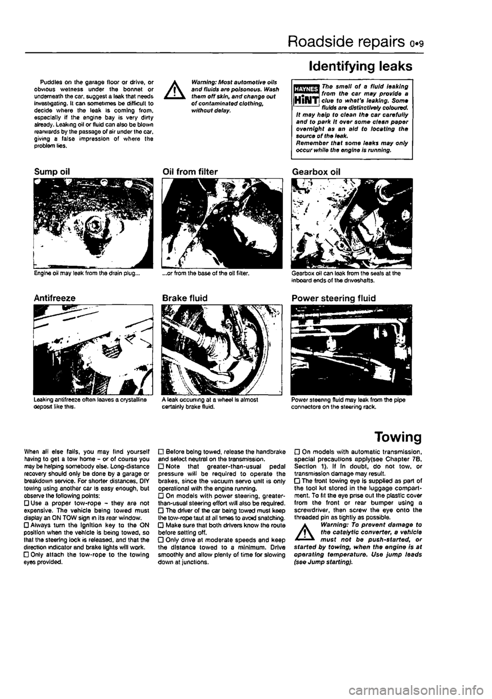
Puddles on the garage floor or drive, or obvious wetness under the bonnet or underneath the car, suggest a leak that needs Investigating. It can sometimes be difficult to decide where the leak is coming from, especially if the engine bay is very dirty already. Leaking oil or fluid can also be blown rearwards by the passage of air under the car, giving a false impression of where the problem lies.
A
Warning: Most automotive oils and fluids aro poisonous. Wash them off skin, and change out of contaminated clothing, without delay.
Identifying leaks
The smell of 0 fluid leaking from the car may provide a clue to what's leaking. Some fluids are distinctively coloured. It may help to clean the car carefully and to park It over some clean paper overnight as an aid to locating the source of the leak. Remember that some leaks may only occur while the engine is running.
Sump oil
Engine oil may leak from the drain plug...
Antifreeze
Leaking antifreeze often leaves a crystalline oeposit like this.
Oil from filter
A leak occurring at a wheel Is almost certainly brake fluid.
Gearbox oil
Gearbox oil can leak from the seals at the inboard ends of the drivoshafts.
Power steering fluid
Power steering fluid may leak from the pipe connectors on the steering rack.
When ail else falls, you may llnd yourself having to get a tow home - or of course you may be helping somebody else. Long-distance recovery should only be done by a garage or breakdown service. For shorter distances. OIY towing using another car is easy enough, but observe the following points: • Use a proper tow-rope - they are not expensive. The vehicle being towed must display an ON TOW sign in its rear window. • Always turn the Ignition key to the ON position when the vehicle is being towed, so that the steering lock is released, and that the direction indicator and brake lights will work. • Only attach the tow-rope to the towing eyes provided.
• Before being towed, release the handbrake and select neutral on the transmission. • Note that greater-then-usual pedal pressure will be required to operate the brakes, since the vacuum servo unit is only operational with the engine running. • On models with power steering, greater-than-usual steering effort will also be required. • The driver of the car being towed must keep the tow-rope taut at all times to avoid snatching. • Make sure that both drivers know the route before setting off. • Only dnve at moderate speeds and keep the distance towed to a minimum. Drive smoothly and allow plenty of time for slowing down at junctions.
Towing
• On models with automatic transmission, special precautions apply(see Chapter 7B. Section 1). If In doubt, do not tow, or transmission damage may result. • The front towing eye is supplied as part of the tool kit stored in the luggage compart-ment. To fit the eye pnse out the plastic cover from the front or rear bumper using a screwdriver, then screw the eye onto the threaded pin as tightly as possible.
A
Warning: To prevent damage to the catalytic converter, e vehicle must not be push'started, or started by towing, when the engine is at operating temperature. Use jump leads (see Jump starting).
Page 26 of 225
Maintenance procedures - petrol models ia./
Every 5000 miles (7500 km) or 6 months
3 Engine oil and filter renewal Ja*
1 Frequent oil and filter changes are the most important preventative maintenance which can be undertaken by the DIY owner. As engine oil ages, it becomes diluted and contaminated, which leads to premature engine wear. 2 Before starting this procedure, gather all Ihe necessary tools and materials. Also make sure that you have plenty of clean rags and newspapers handy, to mop up any spills. Ideally, the engine oil should be warm, as It
will
drain better, and more built-up sludge will
be
removed with it. Tske care, however, not to touch the exhaust or any other hot parts of the engine when working under the vehicle. To avoid any possibility of scalding, and to protect yourself from possible skin irritants end other harmful contaminants in used engine oils, it Is advisable to wear gloves when carrying out this work. Access to the underside of the vehicle will be greatly Improved if it can be raised on a lift, driven onto ramps, or jacked up and supported on axle stands (see Jacking and vehicle support). Whichever method is chosen, make sure that
the
vehicle remains level, or if it is at an angle, that the drain plug Is at the lowest point. 3 Slacken the drain plug about half a turn using an Allen key. Position the draining container under the drain plug, then remove
the plug
completely (see Haynes Hint). 4 Allow some time for the old oil to dram, noting that it may be necessary to reposition
the
container as the oil flow slows to a trickle. 5 After all the oil has drained, wipe off the drain plug with a clean rag, then clean the area around the drain plug opening and refit
(MB
HiNT '
Keep the drain plug pressed Into the sump white unscrewing it by hand the last couple of turns. As the plug releases, move it away sharply so that the stream
of
oil Issuing from the sump runs into the container, net up your sleeve.
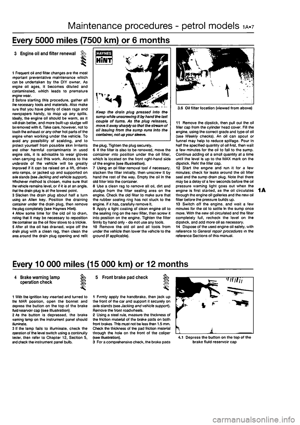
the plug. Tighten the plug securely. 6 It the filter is also to be renewed, move the container into position under tho oil filter, which is located on the front right-hand side of the engine (see illustration). 7 Using an oil filter removal tool if necessary, slacken the filter initially, then unscrew It by hand the rest of the way. Empty the oil in the old filter into the container. 8 Use a clean rag to remove all oil, dirt and sludge from the filter sealing area on the engine. Check the old filter to make sure that the rubber sealing ring has not stuck to the engine. If it has. carefully remove It. 9 Apply a light coating of clean engine oil to the sealing ring on the new filter, then screw it into position on the engine. Tighten the filter firmly by hand only • do not use any tools. 10 Remove the old oil and all tools from under the vehicle then lower the vehicle to the ground (if applicable).
3.6 Oil filter location (viewed from above)
11 Remove the dipstick, then pull out the oil filler cap from the cylinder head cover. Fill the engine, using the correct grade and type of oil (see Weekly checks). An oil can spout or funnel may help to reduce spillage. Pour In half the specified quantity of oil first, then wail a few minutes for the oil to fall to the sump. Continue adding oil a small quantity at a time until the level is up to the MAX mark on the dipstick. Refit the filler cap. 12 Start the engine and run it for a few minutes: check for leaks around the oil filter seal and the sump drain plug. Note that there may be a delay of a few seconds before the oil pressure warning light goes out when the engine is first started, as the oil circulates through the engine oil galleries and the new oil filter before (he pressure builds up. 13 Switch off the engine, and wait a few minutes for the oil to settle In the sump once more. With the new oil circulated and the filter completely full, recheck the level on the dipstick, and add more oil as necessary. 14 Dispose of the used engine oil safely, with reference to General repair procedures in the reference Sections of this manual.
Every 10 000 miles (15 000 km) or 12 months
4 Brake warning lamp ag operation check J§
1 With the ignition key inserted and turned to the MAR position, open the bonnet and depress the button on the top of the brake ftuid reservoir cap (see illustration). 2 As the button is depressed, the brake warning lamp on the instrument panel should Illuminate. 3 If the lamp fails to illuminate, check the operation of the level switch using a continuity tester, then refer to Chapter 12, Section 5, wd check the instrument panel bulb.
5 Front brake pad check
1 Firmly apply the handbrake, then jack up the front of the car and support it securely on axle stands (see Jacking and vehicle support). Remove the front roadwheels, 2 Using a steel rule, measure the thickness of the friction material of the brake pads on both front brakes- This must not be less than 1.5 mm. Check the thickness of the pad friction material through the hole on the front of the caliper (see illustration). 3 For a comprehensive check, the brake pads 4.1 Depress the button on the top of the brake fluid reservoir cap
Page 33 of 225
ia.14 Every 20 000 miles - petrol models
16 Test the operation of the brake servo unit as follows. With the engine off, depress the footbrake four or five times to exhaust the vacuum. Hold the brake pedal depressed, then start the engine. As the engine starts.
there should be a noticeable give In the brake pedal as vacuum builds up. Allow the engine to run for at least tsvo minutes, and then switch it off. If the brake pedal is depressed now. it should be possible to detect a hiss
from the servo as the pedal is depressed. After about four or five applications, no further hissing should be heard, and the pedal shouto feel considerably harder.
Every 30 000 miles (45 000 km) or 3 years
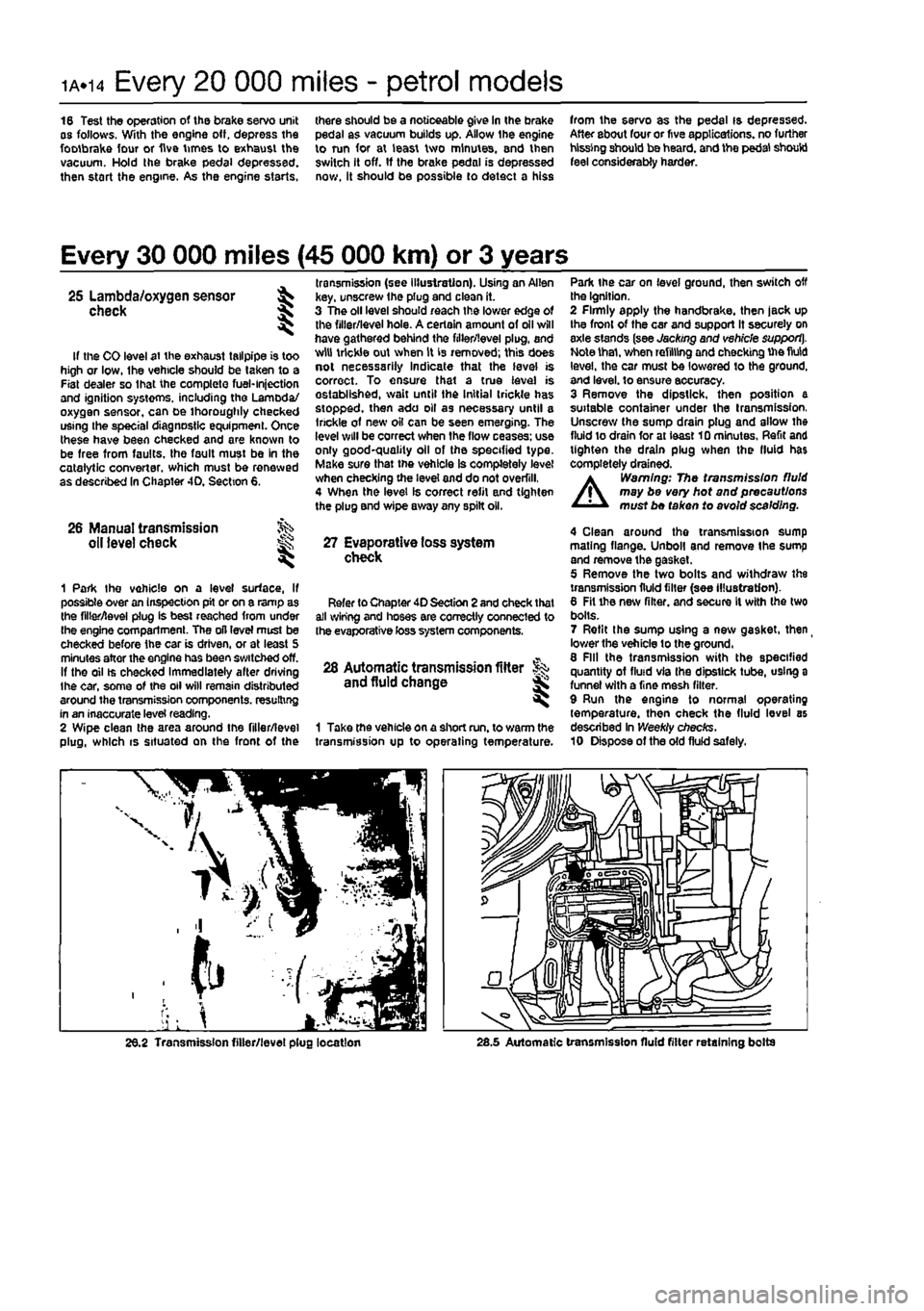
. transmission (see illustration). Using an Allen 25 Lambda/oxygen sensor ^ key, unscrew the plug and clean it. check \ 3 The oil level should reach the lower edge of ^ the filler/level hole. A certain amount of oil will have gathered behind the filler/level plug, and If the CO level at the exhaust tailpipe is too w,u tr,cWe out when is 'e™oved; this does high or low, Ihe vehicle should be taken to a «©l necessarily Indicate that the level is Fiat dealer so lhat the complete fuel-injection correct. To ensure that a true level is and ignition systems, including the Lamoda/ established, wait until the Initial trickle has oxygen sensor, can be thoroughly checked stopped, then ado oil as necessary until a using the special diagnostic equipment. Once ,r,ckle o1 new oil can be seen emerging. The these have been checked and are known to 'W wl" be correct when ,he flow ceases-us® be free from faults, the fault must be in the good-quality oil of the specified type, catalytic converter, which must be renewed Make sur®that vehicle Is completely level as described In Chapter 4D, Section 6. checking the level and do not overfill, 4 When the level Is correct refit and tighten the plug and wipe away any spilt oil.
26 Manual transmission oil level check ^ 27 Evaporative loss system ^ check
1 Park Ihe vehicle on a level surface, If possible over an inspection pit or on a ramp as the filler/level plug is best reached from under Ihe engine compartment. The oil level must be checked before the car is driven, or at least 5 minutes after the engine has been switched off. If the oil ts checked Immediately alter driving the car, some of the oil will remain distributed around the transmission components, resulting in an inaccurate level reading. 2 Wipe clean the area around the filler/level plug, which is situated on the front of the
Refer to Chapter 40 Section 2 and check that all wiring and hoses are correctly connected to the evaporative toss system components.
28 Automatic transmission fitter and fluid change
1 Take the vehicle on a short run. to warm the transmission up to operating temperature.
Park the car on level ground, then switch off the Ignition. 2 Firmly apply the handbrake, then jack up the front of the car and support It securely on axle stands (see Jacking and vehicle support]. Note thai, when refilling and checking Uie fluid level, the car must be lowered to the ground, and level, to ensure accuracy. 3 Remove the dipstick, then position a suitable container under the transmission, Unscrew the sump drain plug and allow the fluid to drain for at ieast 10 minutes. Refit and tighten the drain plug when the fluid has completely drained.
A
Warning: The transmission fluid may be very hot and precautions must be taken to avoid scalding.
4 Clean around the transmission sump mating flange. Unboll and remove the sump and remove the gasket. 5 Remove the two bolts and withdraw the transmission fluid filter {see illustration). 6 Fit the new filter, and secure It with the two bolts. 7 Refit the sump using a new gasket, then
_
lower the vehicle to the ground, 8 Fill the transmission with the specified quantity of fluid via Ihe dipstick tube, using a funnel with a fine mesh filter. 9 Run the engine to normal operating temperature, then check the fluid level as described In Weekly checks. 10 Dispose of the old fluid safely.
26.2 Transmission filler/level plug location 28.5 Automatic transmission fluid filter retaining bolts
Page 34 of 225
Maintenance procedures - petrol models 1A.15
Every 40 000 miles (60 000 km) or 4 years
29 Rear brake shoe check
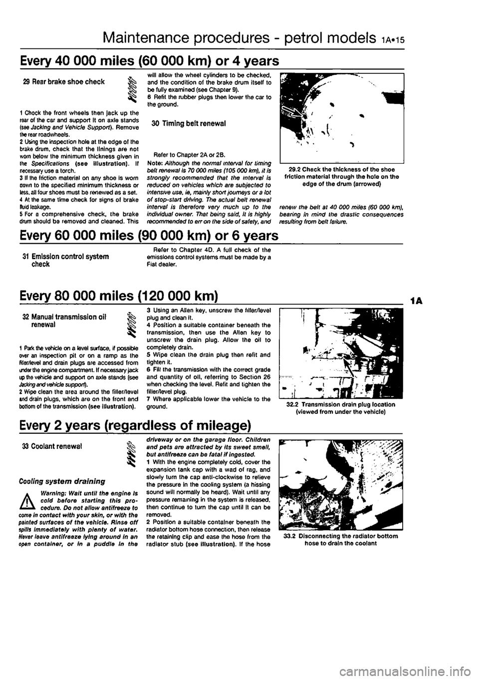
1 Chock the front wheels then Jack up the rear of Ihe car and support it on axle stands (see Jacking and Vehicle Support). Remove the rear roadwheels. 2 Using the inspection hole at the edge of the brake drum, check that the linings are not worn below Ihe minimum thickness given in the Specifications (see illustration). If necessary use a torch. 3 If the friction material on any shoe is worn down to the specified minimum thickness or
less,
all four shoes must be renewed as a set. 4 At the same time check for signs of brake
Kutti
leakage. 5 For a comprehensive check, the brake drum should be removed and cleaned. This
will allow the wheel cylinders to be checked, and the condition of the brake drum itself to be fully examined (see Chapter 9). 6 Refit the lubber plugs then lower the car to the ground.
30 Timing belt renewal
Refer to Chapter 2A or 2B. Note: Although the norma/ interval for timing belt renewal is 70 000 miles (105 000 km), it is strongly recommended that the interval Is reduced on vehicles which are subjected to intensive use. ie, mainly short journeys or a lot of stop-start driving. The actual belt renewal interval is therefore very much up to the individuaf owner. That being said, it is highly recommended to err on the side of safety, and
29.2 Check the thickness of the shoe friction material through the hole on the edge of the drum (arrowed)
renew the belt at 40 000 miles (60 000 km), bearing in mind the drastic consequences resulting from belt failure.
Every 60 000 miles (90 000 km) or 6 years
31 Emission control system check
Refer to Chapter 4D. A full check of the emissions control systems must be made by a Fiat dealer.
Every 80 000 miles (120 000 km)
32 Manual transmission all renewal S
1 Park the vehicle on a level surface, if possible over an inspection pit or on a ramp as the filler/level and drain plugs are accessed from order
the
engine compartment. If necessary
Jack
ip the vehicle and support on axle stands (see
Jacking and vehicle
support). 2 Wipe clean the area around the filler/leval And drain plugs, which are on the front and bottom of the transmission (see illustration).
3 Using an Allen key. unscrew the filler/level plug and clean it. 4 Position a suitable container beneath the transmission, then use the Allen key to unscrew the drain plug. Allow the oil to completely drain. 5 Wipe clean the drain plug then refit and tighten It. 6 Fill the transmission with ihe correct grade and quantity of oil, referring to Section 26 when checking the level. Refit and lighten the filler/level plug. 7 Where applicable lower the vehicle to the ground. 32.2 Transmission drain plug location (viewed from under the vehicle)
Every 2 years (regardless of mileage)
33 Coolant renewal
I
Cooling system draining
A
Warning: Walt until the engine Is cold before starting this pro-cedure. Do not allow antifreeze to come In contact with your skin, or with the painted surfaces of the vehicle. Rinse off spills immediately with plenty of water.
Ndver
leave antifreeze lying around In an open container, or fn a puddle In the
driveway or on the garage floor. Children and pets are attracted by its sweet smell, but ant/freeze can be fatal if ingested. 1 With the engine completely cold, cover the expansion tank cap with a wad of rag. and slowly turn the cap anticlockwise to relieve the pressure in the cooling system (a hissing sound will normally be heard). Wait until any pressure remaining in the system is released, then continue to tum the cap until it can be removed. 2 Position a suitable container beneath the radiator bottom hose connection, then release the retaining clip and ease the hose from the radiator stub (see illustration). If the hose 33.2 Disconnecting the radiator bottom hose to drain tho coolant
Page 42 of 225
ib.6 Maintenance procedures - diesel models
Every 5000 miles (7500 km) or 6 months
3 Engine oil and filter renewal it-
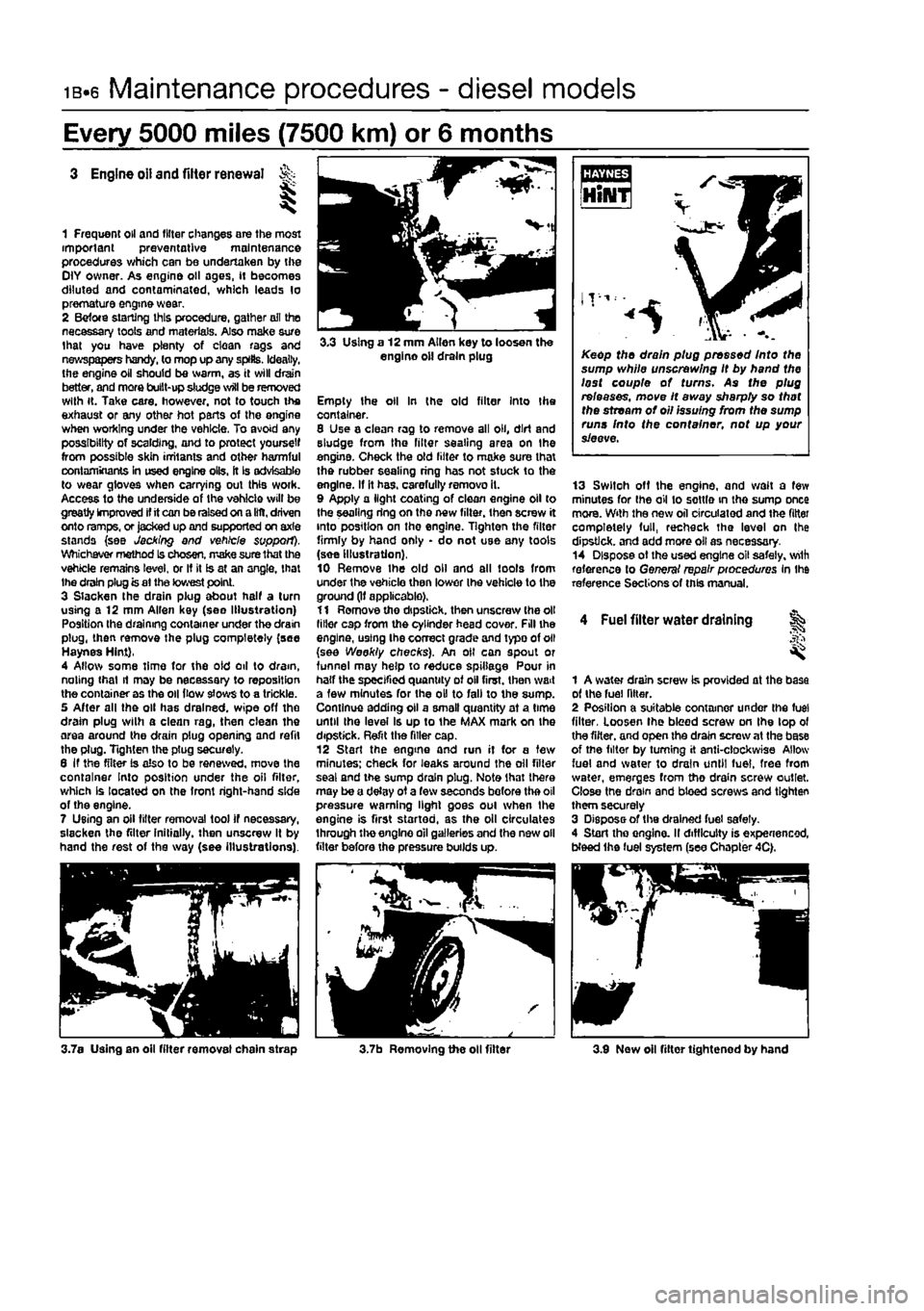
1 Frequent oil and filter changes are the most important preventative maintenance procedures which can be undertaken by the OlY owner. As engine oil ages, if becomes diluted and contaminated, which leads lo premature engine wear. 2 Befote starting this procedure, gather ail the necessary tools and materials. Also make sure that you have plenty of clean rags and newspapers handy, to mop up any splits. Ideally, the engine oil should be warm, as it will drain better, and more built-up sludge will be removed with it. Take care, however, not to touch the exhaust or any other hot parts of the engine when working under the vehicle. To avoid any possibility of scalding, and to protect yourself from possible skin irritants and other harmful contaminants in used engine oils, it is advisable to wear gloves when carrying out this woik. Access to the underside of the vehicle will be greatly improved if it can be raised on a lilt, driven onto ramps, or jacked up and supported on axle stands {see Jacking and vehicle support). Whichever method Is chosen, make sure that the vehicle remains level, or If it is at an angle, that Ihe drain plug is at the lowest point. 3 Slacken the drain plug about half a turn using a 12 mm Allen key (see Illustration) Position the draining container under the drain plug, then remove the plug completely (see Haynes Hint), 4 Allow some time for the oid oil to dram, noting that it may be necessary to reposition the container as the oil (tow slows to a trickle. 5 After all the oil has drained, wipe off the drain plug wilh a clean rag, then clean the area around the drain plug opening and refit the plug. Tighten the ptug securely. 6 If the filter is also to be renewed, move the container Into position under the oil filter, which Is located on the front right-hand side of the engine. 7 Using an oil filter removal tool if necessary, slacken the filter initially, then unscrew It by hand the rest of the way (see illustrations).
3.3 Using a 12 mm Allen key to loosen the engine oil drain plug
Empty the oil In (he old filter Into Ihe container. 8 Use a clean rag to remove all oil, dirt and sludge from the filter sealing area on the engine. Check the old lilter to make sure thai the rubber sealing ring has not stuck to the engine. If it has. carefully removo it. 9 Apply a light coating of clean engine oil to the sealing ring on the new filter, then screw it into position on the engine. Tighten the filter firmly by hand only • do not use any tools (see Illustration), 10 Remove Ihe old oil and all tools from under the vehicle then lower Ihe vehicle to the ground (If applicable). 11 Remove tho dipstick, then unscrew (he oil liiler cap from the cylinder head cover. Fill the engine, using Ihe correct grade and typo of oil (see Weekly checks). An oil can spout or funnel may help to reduce spillage Pour in half the specified quantity of oil first, then wait a few minutes for the oil to fall to the sump. Continue adding oil a smalt quantity at a time until Ihe level Is up to the MAX mark on the dipstick. Refit the filler cap. 12 Start the engine and run it for a tew minutes; check for leaks around the oil filter seal and the sump drain plug. Note that there may be a delay of a few seconds before the oil pressure warning light goes oul when the engine is first started, as the oil circulates through the engine oil galleries and the new oil filter before the pressure builds up.
Keep the drain plug pressed Into the sump while unscrewing It by hand the lost couple of turns. As the plug releases, move It away sharpty so that the stream of oil issuing from the sump runs Into the container, not up your sieeve.
13 Switoh off the engine, and wait a few minutes for Ihe oil to settle in the sump once mora. With the new oil circulated and the fitter completely full, recheck the level on Ihe dipstick, and add more oil as necessary. 14 Dispose ot the used engine oil safely, wilh reference lo General repair pioceduros In Ihe reference Sections of this manual.
4 Fuel filter water draining ^
1 A water drain screw is provided at the base of the fuel filter. 2 Position a suitable container under ihe fuel filter, Loosen Ihe bleed screw on the lop ol the filter, and open the drain screw at the base of tne filter by turning it anti-clockwise Allow fuel and water to drain until fuel, free from water, emerges from tho drain screw outlet. Close tne drain and bleed screws and tighten them securely 3 Dispose of the drained fuel safely. 4 Start tho onglno. II difficulty is experienced, Weed the fuel system (see Chapter 4C).
3.7a Using an oil fitter removal chain strap 3.7b Removing the oil filter 3.9 Now oil filter tightened by hand
Page 43 of 225
Maintenance procedures - diesel models ib.?
Every 10 000 miles (15 000 km) or 12 months
5 Brake warning lamp operation check 1
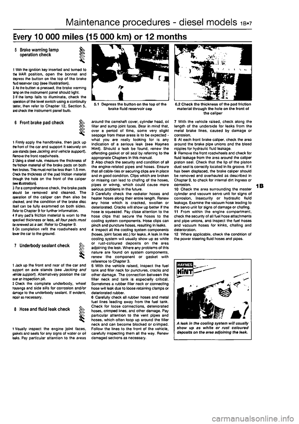
1 With Ihe ignition Key inserted and turned to the MAR position, open the bonnet and depress the button on the top of the brake
fluid
reservoir cap (see illustration). I
As
the button is pressed, the brake warning
lamp
on the instrument panel should light. 3 If Ihe lamp fails to illuminate, check the operation of the level switch using a continuity taster, then refer to Chapter t2, Section 5,
and
check the Instrument panel bulb.
6 Front brake pad check ^
I
1 firmly apply Ihe handbrake, then jack up the front of the car and support it securely on arie stands (see Jacking and vehicle support). Remove the front roadwheels. 2 Using a steel rule, measure the thickness of
the
friction material of the brake pads on both brakes. This must not be less than 1.5 mm. Ctefc the thickness of the pad friction material through the hole on the front of the caliper
|see
lustration), 3
For a
comprehensive check, the brake pads should be removed and cleaned. The operation of the caliper can then also bo checked, and the condition of the brake disc iteeil can be fully examined on both sides. Refer to Chapter 9 for further Information. 4 If any pad's friction material Is worn to the specified thickness or less, all lour pads must to renewed as a set. Refer to Chapter 9. 5 On completion refit the roadwheels and lower the car to the ground.
7 Underbody sealant check f^
1 Jack up the front and rear of the car and support on axle stands (see Jacking and
vehicle
support). Alternatively position the car over
an
Inspection pit. 2 Check the complete underbody, wheel housings and side sills for corrosion and/or damage to the underbody sealant. If evident,
rapairi
8
Hose
and fluid leak check
1 Visually inspect the engine Joint faces. g3skets and seals for any signs of water or oil leaks. Pay particular attention to the areas
5.1 Depress tho button on the top of the brake fluid reservoir cap
around the camshaft cover, cylinder head, oil filter and sump joint faces. Bear in mind that, over a period of time, some very slight seepage from these areas is to be expected -what you are really looking for is any indication of a serious leak (see Haynes Hint). Should a teak be found, renew the offending gasket or oil seal by referring to the appropriate Chapters In this manual, 2 Also check the security and condition of all the engine-related pipes and hoses. Ensure thai all cable-ties or securing clips are In place and in good condition. Clips which are broken or missing can lead to chafing of the hoses, pipes or wiring, which could cause more serious problems In the future. 3 Carefully check the radiator hoses and heater hoses along their entire length. Renew any hose which is cracked, swollen or deteriorated. Cracks will show up better If the hose is squeezed. Pay close attention to the hose clips that secure the hoses to the cooling system components. Hose clips can pinch and puncture hoses, resulting in leaks. 4 Inspect all the cooling system components (hoses. )olnt faces etc.) for leaks. A leak in the cooling system will usually show up as white or rust-coloured deposits on the area adjoining the leak, Where any problems of this nature are found on system components, renew the component or gasket with reference to Chapter 3. 5 With the vehicle raised, inspect the fuel tank and filler neck for punctures, cracks and other damage, The connection between the filler neck and tank is especially critical. Sometimes a rubber filler neck or connecting hose will leak due to loose retaining clamps or deteriorated rubber. 6 Carefully check all rubber hoses and metal fuel lines leading away from the fuel tank. Check for loose connections, deteriorated hoses, crimped lines, and other damage. Pay particular attention to the vent pipes and hoses, which often loop up around the filler neck and can become blocked or crimped. Follow the lines to the front of the vehicle, carefully Inspecting them all the way. Renew damaged sections as necessary.
6.2 Check the thickness of the pad friction material through the hote on the front of the caliper
7 With the vehicle raised, check along the length of the underside for leaks from the metal brake lines, caused by damage or corrosion. 8 At each front brake caliper, check the area around the brake pipe unions and the bleed nipples for hydraulic fluid leakage, 9 Remove the front roadwheels and chock for fluid leakage from the area around the caliper piston seal. Check that the tip of the piston dust seal is correctly located in its groove. If it has been displaced, the brake caliper should be removed and overhauled as described in Chapter 9, to check for internal dirt Ingress or corrosion. 10 Check the area surrounding the master cylinder and vacuum servo unit for signs of corrosion, Insecurity or hydraulic fluid leakage. Examine the vacuum hose leading to the servo unit for signs of damage or chafing. 11 From within the engine compartment, check the security of all fuel hose attachments and pipe unions, and Inspect the fuel hoses and vacuum hoses for kinks, chafing and deterioration. 12 Where applicable, check the condition of the power steering fluid hoses and pipes.
A leak in the cooling system will usually show up as white or rust coloured deposits on the area adjoining the leak.
Page 48 of 225
1B«12 Every 20 000 miles - diesel models
21 Road test
Instruments and electrical equipment 1 Check the operation of atl instruments and electrical equipment. 2 Make sure that all instruments read correctly, and switch on all electrical equipment rn turn, to check that It functions properly. Steering and suspension 3 Check for any abnormalities in the steering, suspension, handling or road feel. 4 Drive the vehicle, and check that there are no unusual vibrations or noises. 5 Check that the steering feete positive, with no excessive sloppiness, or roughness, and check for any suspension noises when cornering and driving over bumps. Drivetrain 6 Check (he performance of the engine, clutch, transmission and driveshafts.
7 Listen for any unusual noises from the engine, clutch and transmission. 8 Make sure that the engine runs smoothly when Idling, and that there is no hesitation when accelerating. 9 Check that the clutch action is smooth and progressive, that tho drive is taken up smoothly, and that the pedal travel Is not excessive. Also listen for any noises when the clutch pedal is depressed. 10 Check that all gears can be engaged smoothly without noise, and that the gear lever action Is not abnormally vague or notchy. 11 Listen for a metallic clicking sound from ihe front of the vehicle, as the vehicle « driven slowly In a circle with the steering on full-lock. Carry out this check In both directions, if a clicking noise is heard, this Indicates wear in a driveshaft |oinl, in which case renew the joint if necessary.
Check the braking system 12 Make sure that the vehicle does not pull to one side when braking, and that the wheels do not lock prematurely when braking hard.
13 Check that there Is no vibration through the steering when braking. 14 Check that the handbrake operates correctiy without excessive movement of th« lever, end that it holds the vehicle stationery on a slope. 15 Test the operation of the brake servo unit as follows. With the engine off, depress the footbrake four or five times to exhaust the vacuum. Hold the brake pedal depressed, then start the engine. As the engine starts, there should be a noticeable give In the brake pedal as vacuum builds up. Allow the engine to run for at least two minutes, and then switch it off. If the brake pedal is depressed now, it should be possible to detect a hiss from the servo es the pedal is depressed. After about four or five applications, no fimher hissing should be heard, and the pedal should feel considerably harder. Note: The vacuum for the servo unit is provided by the vacuum pump mounted on the left-hand end of t/ie cylinder head.
Every 30 000 miles (45 000 km) or 3 years
22 Manual transmission oil level check ;5§
1 Park the vehicle on a level surface. If possible over an inspection pit or on a ramp as the filler/level plug is best reached from under Ihe engine compartment. The oil level must be checked before the car Is driven, or at least 5 minutes after the engine has been switched off. If the oil is checked Immediately after driving the car. some of the oil will remain distnbuted around the transmission compo-nents, resulting In an inaccurate level reading. 2 Wipe clean the area around the filler/level plug, which is situated on tho front of the
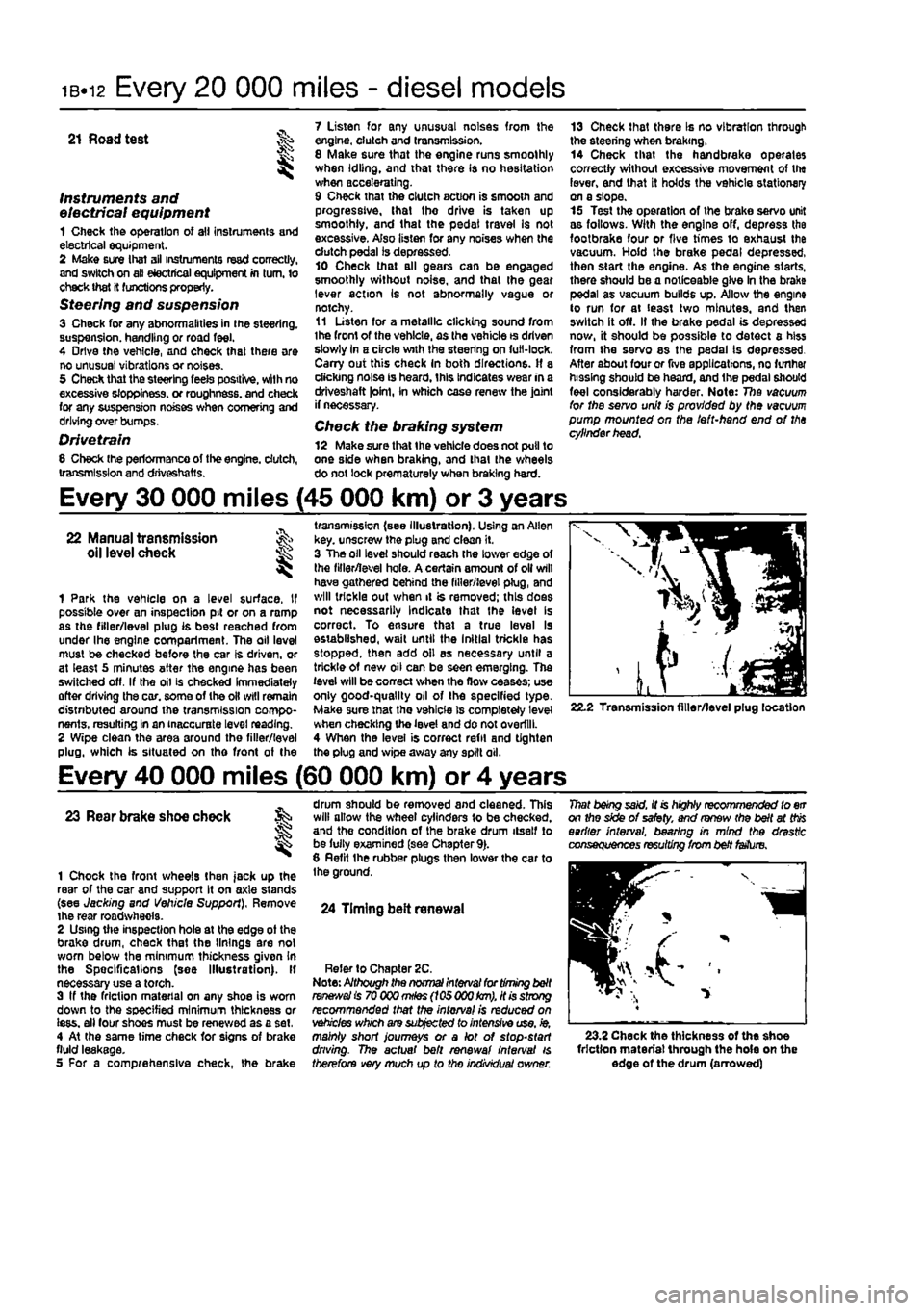
transmission (see illustration). Using an Allen key. unscrew the plug and clean it. 3 The oil level should reach the lower edge of the filler/level hole. A certain amount of oil will have gathered behind the filler/level plug, and will trickle out when it is removed; this does not necessarily Indicate that the level Is correct. To ensure that a true level Is established, wait until the Initial trickle has stopped, then add oil as necessary until a trickle of new oil can be seen emerging. The level will be correct when the flow ceases; use only good-quality oil of the specified type-Make sure that the vehicle Is completely level when checking the level and do not overfill. 4 When the level is correct refit and tighten the plug and wipe away any spilt oil.
22.2 Transmission filler/level plug location
Every 40 000 miles (60 000 km) or 4 years
23 Rear brake shoe check
1 Chock the front wheels then jack up the rear of the car and support It on axle stands (see Jacking and Vehicle Support), Remove the rear roadwhecla. 2 Using the inspection hole at the edge ot the brake drum, check that the linings are not worn below the minimum thickness given In the Spec ifi cat Ions (see Illustration). If necessary use a torch. 3 If the friction material on any shoe is worn down to the specified minimum thickness or iess. all four shoes must be renewed as a set, 4 At the same time check for signs of brake fluid leakage. 5 For a comprehensive check, the brake
drum should be removed and cleaned. This will allow the wheel cylinders to be checked, and the condition of the brake drum itself to be fully examined (see Chapter 9). 8 Refit the rubber plugs then lower the car to the ground.
24 Timing belt renewal
Refer to Chapter 2C. Note: Although the normal interval for timing belt
ranees/a!
is 70 000
mHes
(105 000
km),
it is strong recommended that the interval is reduced on vehicles which are subjected to intensive use, ie, mainly short journeys or a lot of stop-start driving. The actual belt renewal interval is therefore very much up to tho individual owner.
That being said, it is highly recommended to err on the side of safety, and renew (he belt at
this
earlier interval, bearing in mind the drastic consequences resulting from belt fetfure.
23.2 Check the thickness of the shoe friction material through the hole on the edge of the drum (arrowed)
Page 49 of 225
Maintenance procedures - diesel models 1B.13
Every 60 000 miles (90 000 km) or 6 years
Refer to Chapter 40. A full chock of the 26 Emissions control systems emissions control systems must be made by a check Fiat dealer.
Every 80 000 miles (120 000 km)
26 Manual transmission ,v->> oil renewal K
1 Pak the vehicle on a level surface, if possible over an inspection pit or on a ramp as the filer/level and drain plugs are accessed from
under the
engine compartment, ff necessary tack up Ihe vehicle and support on axle stands (see Jacking and
vehicle
support). 2
Wipe
clean the area around the filler/! a vol and vain plugs, which are situated on the front and bottom of the transmission (see Illustration}.
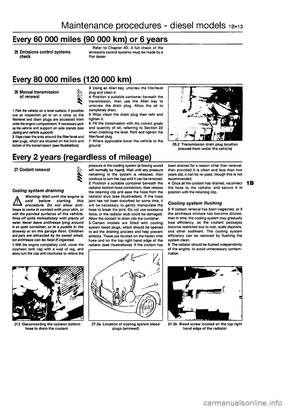
3 Using an Allen key, unscrew the fillor/level plug and clean it. 4 Position a suitable container beneath the transmission, then use the Allen key to unscrew the drain plug. Allow the oil to completely dram. 5 Wipe clean the drain plug then refit and tighten It. 6 Fill the transmission with the correct grade and quantity of oil, referring to Section 22 when checking the level. Refit and tighten the filler/level plug. 7 Where applicable lower the vehicle to the ground. 26.2 Transmission drain plug location (viewed from undor tho vohlcle)
Every 2 years (regardless of mileage)
27
Coolant renewal St I
Coo//ng system draining
A
Warning: Wait until the engine is coid before starting this procedure. Do not allow anti-fnue to come in contact with your skin, or with the painted surfaces of the vehicle.
Rinse
off spills immediately with plenty of water. Never leave antifreeze lying around fh an open container, or in a puddle in the driveway or on the garage floor. Children
and
pets are attracted by Its sweet smell,
bat
antifreeze can be fatal if ingested. 1 With the engine completely cold, cover the expansion tank cap with a wad of rag, and slowly turn the cap anti-clockwise to relieve the
pressure in the cooling system (a hissing sound will normally be heard). Wail until any pressure remaining in the system is released, then continue to turn the cap until it can be removed. 2 Position a suitable container beneath the radiator bottom hose connection, then release the retaining clip and ease the hose from the radiator stub (see Illustration), If the hose joint has not been disturbed for some time, it will be necessary to gently manipulate the hose to break the joint. Do not use excessive force, or the radiator stub could be damaged. Allow the coolant to drain into the container. 3 Certain models are fitted with cooling system bleed plugs, which should be opened to aid the draining process and help prevent airlocks. These are located on the heator Inlet hose and on the top right hand edge of the radiator (see Illustrations), ff the coolant has
been drained for a reason other than renewal, then provided It is clean and less than two years old, it can be re-used, though this is not recommended. 4 Once all the coolant has drained, reconnect the hose to the radiator and secure it in position with the retaining clip.
Cooling system flushing 5 If coolant renewal has been neglected, or if the antifreeze mixture has become diluted, then In time, the cooling system may gradually lose efficiency, as the coolant passages become restricted due to rust, scale deposits, and other sediment. The cooling system efficiency can be restored by flushing tho system clean. 6 The radiator should be (lushed independently of the engine, to avoid unnecessary contam-ination.
27.2 Disconnecting the radiator bottom hose to drain the coolant 27.3a Location of cooling system bleed plugs (arrowed) 27.3b Bleed screw located on the top right hand edge of the radiator
Page 55 of 225
2A*10 SOHC (8-valve) petrol engine in-car repair procedures
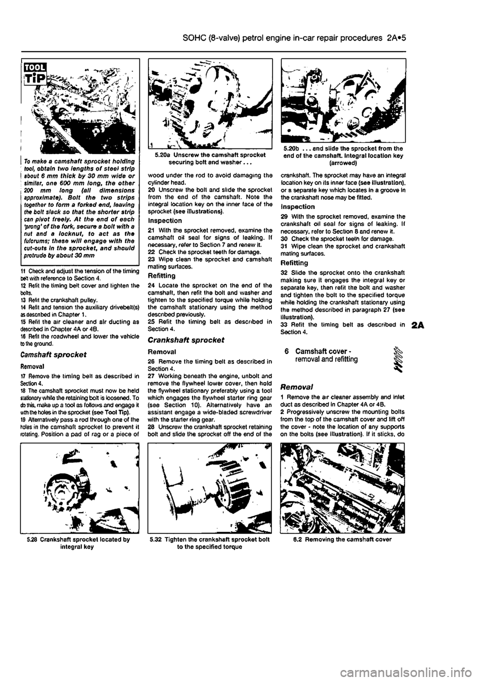
I To make o camshaft sprocket holding ; tool, obtain two lengths of steel strip I about 6 mm thick by 30 mm wide or ; similar, one €00 mm long, the other 200 mm long (all dimensions approximate). Bolt the two strips together to form a forked end, leaving the bolt slack so that the shorter strip can pivot freely. At the end of each 'prong' of the fork, secure a bolt with a nut and a locknut, to act as the fulcrums; these will engage with the cut-outs In the sprocket, and should protrude by about 30 mm
11 Check and adjust the tension of the timing tel with reference to Section 4. 12 Relit Ihe timing belt cover and tighten the bolts. 13 Relit the crankshaft pulley. 14 Refit and tension the auxiliary drivebelt(s)
as
described in Chapter 1. 15 Refil the air cleaner and air ducting as described in Chapter 4A or 48. 16 Refil the roadwheel and lower the vehicle
to the
ground.
Camshaft
sprocket
Removal 17 Remove the timing bell as described in Section 4. 16 The camshaft sprocket must now be held stationary while the retaining bolt is loosened. To
cto this,
make up a tool as follows and engage it
with the
holes
in
the sprocket (see Tool Tip). 19 Alternatively pass a rod through one of the holes in the camshaft sprocket to prevent it rotating. Position a pad of rag or a piece of
integral key
securing bolt and washer...
wood under the rod to avoid damaging the cylinder head. 20 Unscrew the bolt and slide the sprocket from the end of tho camshaft. Note the integral location key on the inner face of the sprocket (see illustrations). Inspection 21 With the sprocket removed, examine the camshaft oil seal for signs of leaking. If necessary, refer to Section 7 and renew it. 22 Check the sprocket teeth for damage. 23 Wipe clean the sprocket and camshaft mating surfaces. Refitting 24 Locate the sprocket on the end of the camshaft, then refit the bolt and washer and tighten to the specified torque while holding the camshaft stationary using the method described previously. 25 Refit the timing belt as described in Section 4.
Crankshaft sprocket
Removal 26 Remove the timing belt as described in Section 4. 27 Working beneath the engine, unbolt and remove the flywheel lower cover, then hold the flywheel stationary preferably using a toot which engages the flywheel starter ring gear (see Section 10). Alternatively have an assistant engage a wide-bladed screwdriver with the stader ring gear. 26 Unscrew the crankshaft sprocket retaining bolt and slide the sprocket off the end of the
^P
5.32 Tighten the crankshaft sprocket bolt to the specified torque
end of the camshaft Integral location key (arrowed)
crankshaft. The sprocket may have an integral location key on its inner face (see illustration), or a separate key which locates in a groove in the crankshaft nose may be fitted. Inspection 29 With the sprocket removed, examine the crankshaft oil seal for signs of leaking. If necessary, refer to Section 8 and renew it. 30 Check the sprocket teeth for damage. 31 Wipe clean the sprocket and crankshaft mating surfaces. Refitting 32 Slide the sprocket onto the crankshaft making sure it engages the integral key or separate key, then refit the bolt and washer and tighten the bolt to the specified torque while holding the crankshaft stationary using the method described in paragraph 27 (see illustration). 33 Refit the timing belt as described in Section 4.
6 Camshaft cover -removal and refitting
Removal 1 Remove the air cleaner assembly and inlet duct as described in Chapter 4A or 4B. 2 Progressively unscrew the mounting bolts from the top of the camshaft cover and lift off the cover • note the location of any supports on the bolts (see illustration). If it sticks, do
6.2 Removing the camshaft cover
Page 67 of 225
2B*7 DOHC (16-valve) petrol engine in-car repair procedures
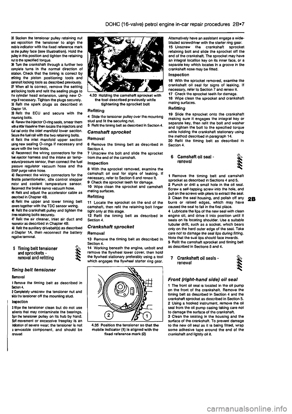
35 Slacken the tensioner pulley retaining nut and reposition the tensioner to align the
mobile
indicator with the fixed reference mark
on the
pulley face (see illustration). Hold the
pdley in
this position and tighten the retaining
nut to the
specified torque. 36 Turn the crankshaft through a further two complete turns In the normal direction of rotation. Check that the timing is correct by alining Ihe piston positioning tools and
camshaft
locking tools as described previously. 37 When all is correct, remove the setting rri
locking
tools and refit the sealing plugs to 1ft© cylinder head extension, using new 0-
nr^s if
necessary. Tighten the plugs securely. 38 Refit the spark plugs as described in Chapter 1A. 39 Refit Ihe ECU and secure with Ihe mooning bolts. 40
Renew the
injector O-ring seals, smear them Kith
8 little
Vaseline then locate the injectors and tef rail onto the inlet manifold lower section.
Saute Ihe fuel rail
with the two retaining bolts. 41 Relit the inlet manifold upper section using new sealing O-rlngs If necessary and
sectre
with the two bolts. 42 Reconnect the wiring connectors for the tot injector harness and the intake air temp-erature/pressure sensor, then connect the fuel pressure regulator vacuum hose and tha
EVAP
purge valve hose. 43 Reconnect the wiring connectors for the ihrottls potentiometer, idle control stepper motor and coolant temperature sensor. Reconnect the brake servo vacuum hose. 44 Refit and adjust the accelerator cable as described in Chapter 4B. 46 Refit the upper and lower timing belt
covers
together with the TDC sensor wiring. 46 Refit the crankshaft pulley and tighten the
three
retaining bolts securely. 47 Refit the air cleaner. Inlet air duct and resonator as described in Chapter 4B. 48
Refit
tha auxiliary drivebelt(s) as described i/t Chapter 1A, then reconnect the battery
S Timing belt tensioner
and
sprockets -
removal
and refitting
Timing
belt tensioner
Removal I
Remove
the timing belt as described in
Section
4. 1 Completely unscrew the tensioner nut and Wiethe tensioner off the mounting stud-Inspection
3 Wipe
the tensioner clean but do not use Kfrents that may contaminate the bearings.
Spin
the tensioner pulley on its hub by hand.
Sfcfl
movement or excessive freeplay is an rcfceticn of severe wear: the tensioner is not 3 serviceable component, and should be nnewsd.
4.33 Holding the camshaft sprocket with the tool described previously while tightening the sprocket bolt Refitting 4 Slide the tensioner pulley over the mounting stud and fit the securing nut. 5 Refit the timing belt as described in Section 4. Camshaft sprocket Removal 6 Remove the timing belt as described in Section 4. 7 Unscrew the bolt and slide the sprocket from the end of the camshaft. Inspection 8 With the sprocket removed, examine the camshaft oil seal for signs of leaking. If necessary, refer to Section 6 and renew it. 9 Check the sprocket teeth for damage. 10 Wipe clean the sprocket and camshaft mating surfaces. Refitting 11 Locate the sprocket on the end of the camshaft, then refit the retaining boll finger tight only at this stage. 12 Refit the timing belt as described in Section 4.
Crankshaft sprocket Removal 13 Remove the timing bell as described In Section 4. 14 Working beneath the engine, unbolt and remove the flywheel lower cover, then hold the flywheel stationary preferably using a tool which engages the flywheel starter ring
<
Alternatively have an assistant engage a wide-bladed screwdriver with the starter ring gear. 15 Unscrew the crankshaft sprocket retaining bolt and slide the sprocket off the end of the crankshaft. The sprocket may have an integral location key on its inner face, or a separate key which locates In a groove in the crankshaft nose may be fitted. Inspection 16 With the sprocket removed, examine the crankshaft oil seal for signs of leaking. If necessary, refer to Section 7 and renew it. 17 Check the sprocket teeth for damage. 18 Wipe clean the sprocket and crankshaft mating surfaces. Refitting 19 Slide the sprocket onto the crankshaft making sure
11
engages the integral key or separate key, then refit the bolt and washer and tighten the bolt to the specified torque while holding the crankshaft stationary using the method described in paragraph 14. 20 Refit the timing belt as described in Section 4.
6 Camshaft
oil
seal -renewal
1 Remove the timing belt and camshaft sprocket as described in Sections 4 and 5. 2 Punch or drill a small hole in the oil seal. Screw a self-tapping screw into the hole, and pull on the screws with pliers to extract the seal. 3 Clean the seal housing, and polish off any burrs or raised edges, which may have caused the seal to fall in the first place. 4 Lubricate the lips of the new seal with clean engine oil, and drive it into position until It seats on its locating shoulder. Use a suitable tubular drift, such as a socket, which bears only on the hard outer edge of the seal. Take care nof to damage the seal lips during fitting. Note that the Seal lips should face inwards. 5 Refit the camshaft sprocket and timing belt as described in Sections 5 and 4.
7 Crankshaft oil seats -renewal I
4.35 Position the tensioner so that the mobile Indicator (1) is aligned with the fixed reference mark (2)
Front (right-hand side) oil seal 1 The front oil seal is located in the oil pump on the front of the crankshaft. Remove the timing belt as described in Section 4 and the crankshaft sprocket as described in Section 5. 2 Using a hooked Instrument, remove the oil seal from the oil pump casing taking care not to damage the surface of the crankshaft. 3 Clean the seating in the housing and the surface of the crankshaft. To prevent damage to the new oil seal as it is being fitted, wrap some adhesive tape around the end of the crankshaft and lightly oil it.