4B 1 FIAT PUNTO 1998 176 / 1.G Repair Manual
[x] Cancel search | Manufacturer: FIAT, Model Year: 1998, Model line: PUNTO, Model: FIAT PUNTO 1998 176 / 1.GPages: 225, PDF Size: 18.54 MB
Page 61 of 225
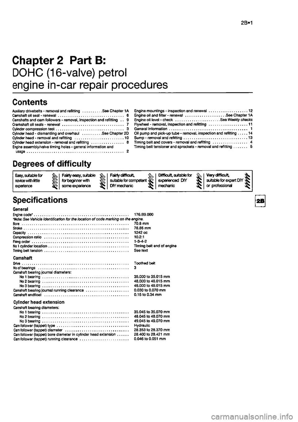
2B»1
Chapter 2 Part B:
DOHC (16-valve) petrol
engine in-car repair procedures
Contents
Auxiliary drlvebelts - removal and refitting See Chapter 1A Camshaft oil seal - renewal 6 Camshafts and cam followers - removal, inspection and refitting .. 9 Crankshaft oil seals • renewal 7 Cylinder compression test 3 Cylinder head - dismantling and overhaul See Chapter 2D Cylinder head • removal and refitting 10 Cylinder head extension • removal and refitting 8 Engine assembly/Valve timing holes - general information and usage 2
Engine mountings - inspection and renewal 12 Engine oil and filter - renewal See Chapter 1A Engine oil level - check See Weekly checks Flywheel - removal, Inspection and refitting 11 General Information 1 Oil pump and pick-up tube - removal, inspection and refitting 14 Sump - removal and refitting 13 Timing belt and covers - removal and refitting 4 Timing belt tensioner and sprockets • removal and refitting 5
Degrees of difficulty
Easy,
sitable
for
J; Fairly
easy,
suitable Fairtydifflcutt, ^
Difficult,
aitabtefcr Very
difficult,
^ nwice
wim
(ttls for beginner with £
suitable
for competent KYmechanic ^ experienced DIY > suitable
for
expert DIY« experience
some
experience £
suitable
for competent KYmechanic ^ mechanic > or professional ^
Specifications
General Engine code* 176.09.000 •Note: See Vehicle Identification for the location of code marking on the engine. Bore 70.8 mm Stroke 78.86 mm Capacity 1242 cc Compression ratio 10.2:1 Firing order 1-3-4-2 No
1
cylinder location Timing belt end of engine Timing belt tension See text
Camshaft Orlve Toothed belt
No
of bearings 3 Camshaft bearing journal diameters: Ho
1
bearing 35.000 to 35.015 mm
Mo
2 bearing 48.000 to 48.015 mm No 3 bearing 49.000 to 49.015 mm Camshaft bearing Journal running clearance 0.030 to 0.070 mm Camshaft endfloat 0.15 to 0.34 mm
Cylinder head extension Camshaft bearing diamelers: No
1
bearing 35.045 to 35.070 mm No 2 bearing 48,045 to 48.070 mm No 3 bearing 49.045 to 49.070 mm
Cam
follower (tappet) type Hydraulic
Cam
follower (tappet) diameter 28.353 to 28.370 mm
Cam
follower (tappet) bore diameter in cylinder head extension 28.400 to 28.421 mm
Cam
follower (tappet) running clearance 0.046 to
0.051
mm
Page 62 of 225
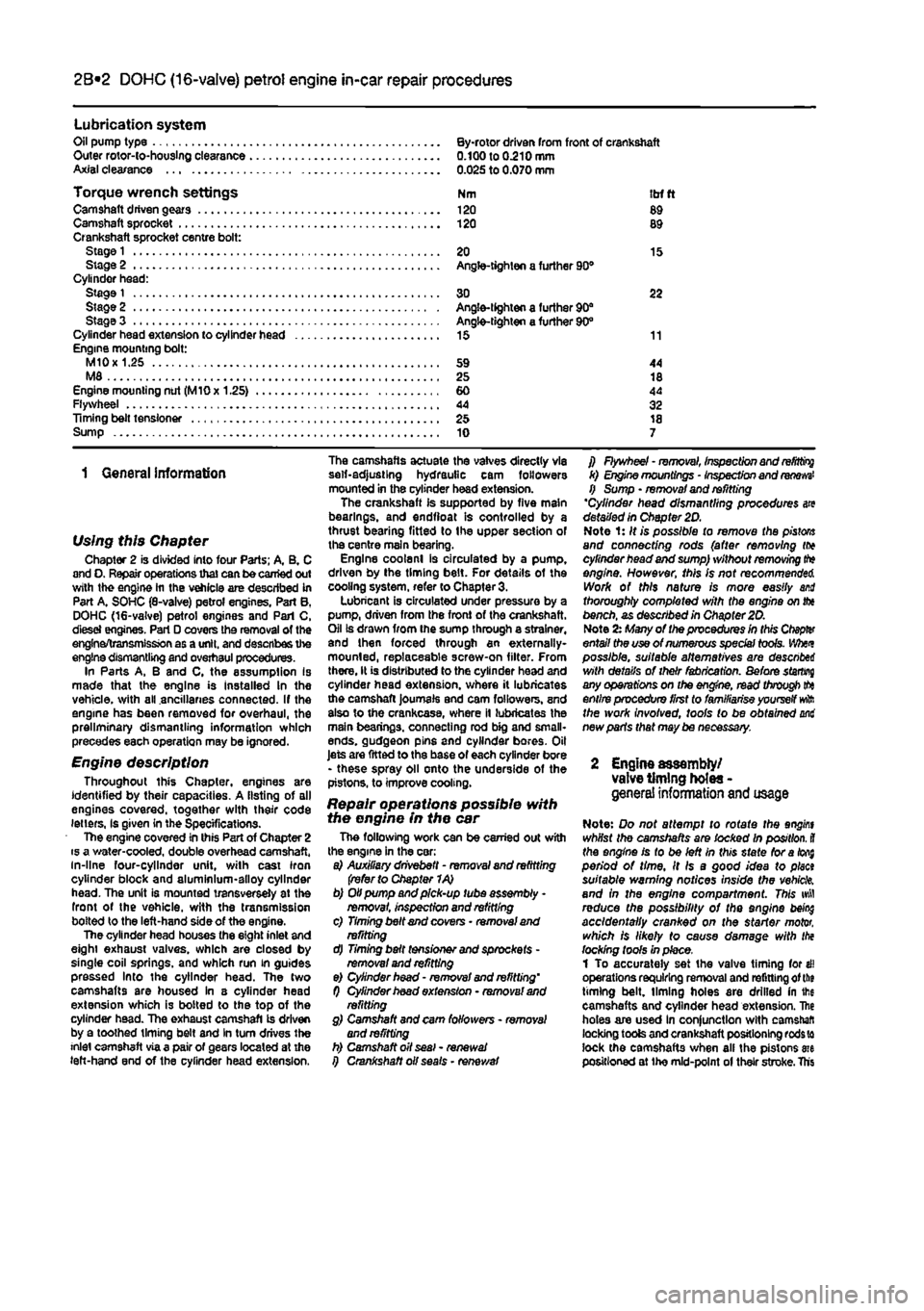
2A*10 SOHC (8-valve) petrol engine in-car repair procedures
Lubrication system Oil pump type By-rotor driven from front of crankshaft Outer rotor-io-houslng clearance 0.100 to 0.210 mm Axial clearance 0.025 to 0.070 mm
Torque wrench settings Nm itrf ft Camshaft driven gears 120 89 Camshaft sprocket 120 89 Crankshaft sprocket centre bolt: Stage
1
20 15 Stage 2 Angle-tighten a further 90® Cylinder head: Stage
1
30 22 Stage 2 Angle-tighten a further 90" Stage 3 Angle-tighten a further 90° Cylinder head extension to cylinder head 15 11 Engine mounting bolt: M10
x
1.25 59 44 M8 25 18 Engine mounting nut (MlOx 1.25) 60 44 Flywheel 44 32 Timing belt tensioner 25 18 Sump 10 7
1 General information
Using this Chapter Chapter 2 is divided into four Parts; A, B. C and O. Repair operations that can be carried out with the engine hi the vehicle are described in Part A. SOHC (8-valve) petrol engines. Part B, DOHC (16-valve) petrol engines and Pari C, dlesei engines. Part D covers the removal of the engine/transmission as a unit, and describes the engine dismantling and overhaul procedures. In Parts A, B and C, the assumption Is made that the engine is Installed In the vehicle, with all ancillaries connected. If the engine has been removed for overhaul, the preliminary dismantling information which precedes each operation may be ignored.
Engine description Throughout this Chapter, engines are identified by their capacities. A listing of all engines covered, together with their code letters, Is given in the Specifications. The engine covered in this Part of Chapter 2 is a water-cooled, double overhead camshaft, in-line four-cylinder unit, with cast iron cylinder block and aluminium-alloy cylinder head. The unit is mounted transversely at the front of the vehicle, with the transmission bolted to the left-hand side of the engine. The cylinder head houses the eight inlet and eight exhaust valves, which are closed by single coil springs, and which run in guides pressed Into the cylinder head. The two camshafts are housed in 8 cylinder head extension which is bolted to the top of the cylinder head. The exhaust camshaft is driven by a toothed timing belt and In turn drives the inlet camshaft via a pair of gears located at the left-hand end of the cylinder head extension.
The camshafts actuate the valves directly via self-adjusting hydraulic cam followers mounted in the cylinder head extension. The crankshaft is supported by five main bearings, and endfioat is controlled by a thrust bearing fitted to (he upper section of the centre main bearing. Engine coolanl is circulated by a pump, driven by the timing belt. For details of the cooling system, refer to Chapter 3. Lubricant is circulated under pressure by a pump, driven from the front of the crankshaft. Oil is drawn from Ihe sump through a strainer, and then forced through an externally-mounted, replaceable screw-on filter. From there, It is distributed to the cylinder head and cylinder head extension, where it lubricates the camshaft journals and cam followers, and also to the crankcase, where it lubricates the main bearings, connecting rod big and small-ends. gudgeon pins and cylinder bores. Oil Jets are fitted to the base of each cylinder bore - these spray oil onto the underside of the pistons, to improve cooling.
Repair operations possible with the engine in the car The following work can be carried out with the engine in the car: a) Auxiliary drivebett - removal and refitting (refer to Chapter 1A) b) Oil pump and pick-up tube assembly -removal, Inspection and refitting c) Timing belt and covers • removal and refitting d) Timing belt tensioner and sprockets -removal and refitting e) Cylinder head - removal and refitting' f) Cylinder hoad extension - removal and refitting g) Camshaft and cam followers - removal and refitting h) Camshaft oil seal - renewal i) Crankshaft oil seals • renewal
f) Flywheel - removal, inspection and
refitting
k) Engine mountings - Inspection and
renews'
f) Sump • removal and refitting 'Cylinder head dismantling procedures are detailed In Chapter 2D. Note 1: It is possible to remove the
pistons
and connecting rods (after removing (to cylinder head and sump) without removing
tt*»
engine. However, this Is not recommended. Work of this nature is more easily and thoroughly completed with the engine on fix bench, as described in Chapter 20. Note
2x
Many of the procedures in this Ctopfer entail the use of numerous special tools. Whet possible, suitable alternatives are descnbei with details of their fabrication. Before starring any operations on the engine, read through
tto
entire procedure first to familiarise yourself
wft
the work involved, tools to be obtained mi new parts that may be necessary.
2 Engine assembly/ valve timing holes -genera! information
and
usage
Note: Do not attempt to rotate the angint whilst the camshafts are locked In position,
il
the engine is to be left in this state foratofi$ period of time. It Is a good idea to plect suitable warning notices inside the vehicle, and in the engine compartment. This wfl reduce the possibility of the engine being accidentally cranked on the starter motor, which is likely to cause damage with the locking tools In place. 1 To accurately set the valve timing for ell operations requiring removal and refitting of
the
timing belt, liming holes are drilled in ihe camshafts and cylinder head extension. Ihe holes are used In conjunction with camshaft locking tools and crankshaft positioning
rods w
lock the camshafts when all the pistons me positioned at the mid-point of their stroke. Ths
Page 63 of 225
2B*3 DOHC (16-valve) petrol engine in-car repair procedures
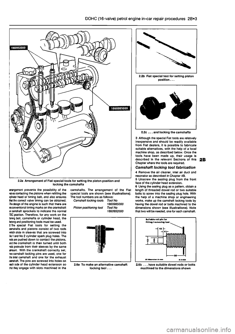
2.2s Arrangement of Fiat special tools for setting the piston position and locking the camshafts
arrangement prevents the possibility of the vaivescontacting the pistons when refitting the cinder head or timing belt, and also ensures tet the correct valve timing can be obtained.
The design
of the engine is such that there are n> conventional timing marks on the crankshaft
er
camshaft sprockets to indicate the normal 70C position. Therefore, for any work on the lining belt, camshafls or cylinder head, the b&ng
and
positioning tools must be used.
2 The
special Fiat tools for setting the camshafts and pistons consist of two rods ttikh slide in sleeves that are screwed into
So
t and No 2 cylinder spark plug holes. The
rods are
pushed down to contact the pistons, ird the crankshaft is then turned until both tods protrude from their sleeves by the same enount. With the crankshaft correctly set,
ti»o
camshaft locking pins are used, one for tM inlet camshaft and one for the exhaust earretaft. The pins are screwed into holes on *ach »de of the cylinder head extension so M they engage with slots machined In (he
2.2b Fiat special tool for setting piston position...
camshafts. The arrangement of the Rat special tools are shown (see illustrations). The tool numbers are as follows: Camshaft locking toots Toot No 1860985000 Piston positioning tool Toot No 1860992000
2.2c ... and locking the camshafts
3 Although the special Fiat tools are relatively inexpensive and should be readily available from Flat dealers, it is possible to fabricate suitable alternatives, with the help of a local machine shop, as described below. Once the tools have been made up, their usage Is described In the relevant Sections of this Chapter where the tools are required. Camshaft locking tool fabrication 4 Remove the air cleaner, inlet air duct and resonator as descnbed in Chapter 4B. 5 Unscrew the sealing plug from the front face of the cylinder head extension. 6 Using the sealing plug as a pattern, obtain a length of threaded dowel rod or two suitable bolts to screw into the sealing plug hole. With the help of a machine shop or engineering works, make up the camshaft locking toots by having the dowel rod or bolts machined to the dimensions shown (see illustrations). Note that two will be needed, one for each camshaft.
Suitabt* roll pin (or titling /
ramoviitg
tool
-J 10 h -4 h
AT —
T
—
2,6a To make an alternative camshaft locking tool... 2.6b ... have suitable dowel rods or bolts machined to the dimensions shown
Page 64 of 225
2B*4 DOHC (16-valve) petrol engine in-car repair procedures
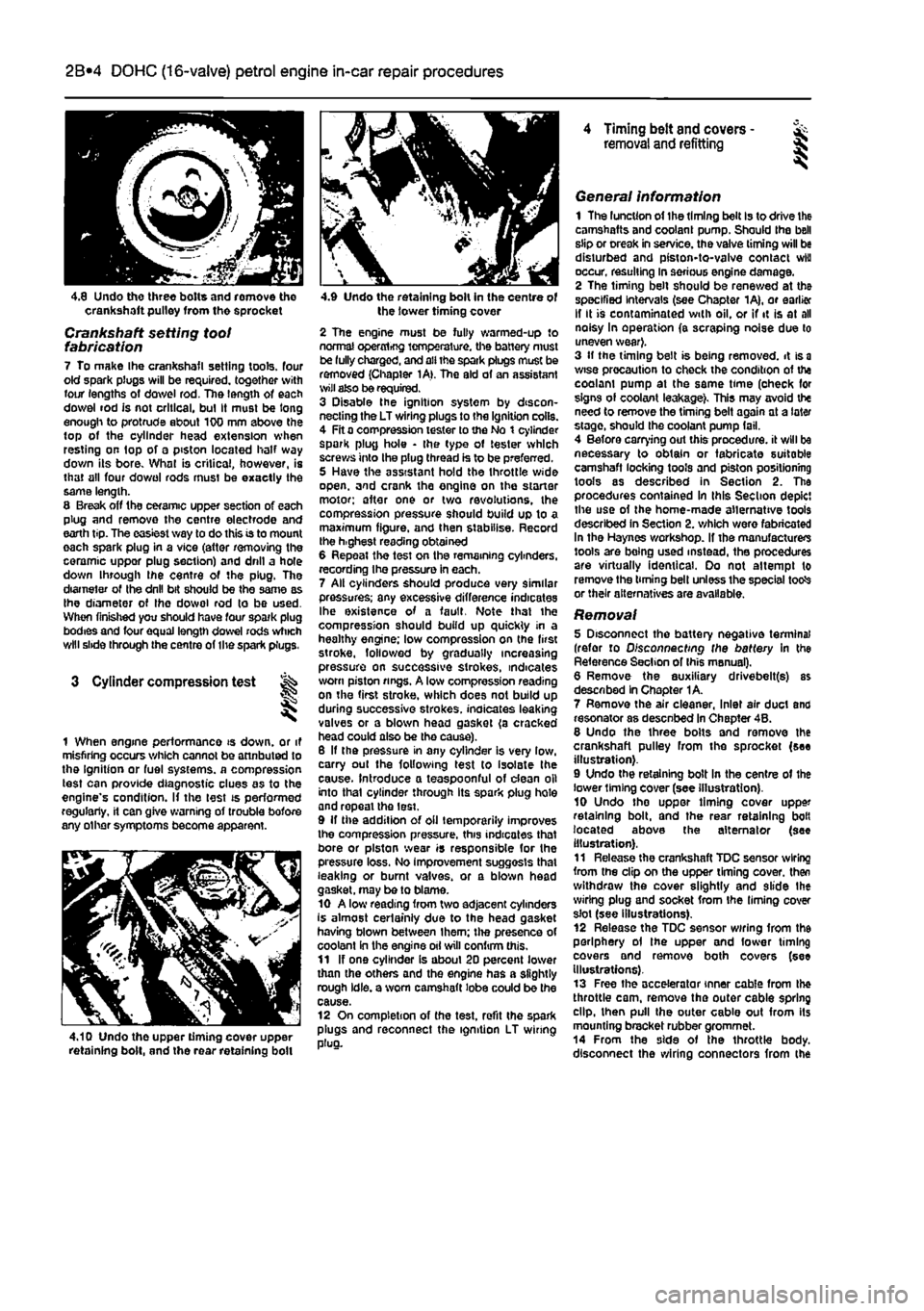
4.8 Undo three bolts and romove tho crankshaft pulley from the sprocket
Crankshaft setting toot fabrication 7 To make Ihe crankshafl setting tools, four old spark plugs will be required, together with four lengths of dowel rod. The length of each dowel rod is not critical, bul It must be long enough to protrude about 100 mm above the top of the cylinder head extension when resting on top of a piston located half way down its bore. What is critical, however, is that all four do wo I rods must be exactly the same length. 8 Break off the ceramic upper section of each plug and remove the centre electrode and earth tip. The easiest way to do this is to mount each spark plug in a vice (attar removing the ceramic uppor plug section) and drill a hole down through ihe centre of the plug. The diameter of Ihe drill bit should be the same as Ihe diameter of Ihe dowol rod to be used. When finished you should have four spark plug bodies and four equal length dowel rods which will slide through the centre of the spark plugs.
3 Cylinder compression test
1 When engine performance is down, or it misfiring occurs which cannot be attnbuted to the Ignition or fuel systems, a compression test can provide diagnostic clues as to the engine's condition. If the lest is performed regularly, it can give warning of trouble bofore any other symptoms become apparent.
4.10 Undo the upper timing cover upper retaining bolt, and the rear retaining boll
4.9 Undo the retaining bolt in the centre of the lower timing cover
2 The engine must be fully warmed-up to normal operxrtrfjg temperature, the battery must be fully charged, and all the spark plugs muse be removed (Chapter 1A>. The aid of an assistant wilt also be required. 3 Disable the ignition system by discon-necting the LT wiring plugs to the Ignition coils. 4 Fit a compression tester to the No t cylinder spark plug hole • the type of tester which screws into the plug thread is to be preferred. 5 Have the assistant hold the throttle wide open, and crank the engine on the starter motor; after one or two revolutions, the compression pressure should build up to a maximum figure, and then stabilise. Record the h.ghest reading obtained 6 Repeat the test on the remaining cylinders, recording Ihe pressure in each. 7 All cylinders should produce very similar pressures; any excessive difference indicates Ihe existence of a fault. Note that the compression should build up quickly in a healthy engine; low compression on (he first stroke, followed by gradually increasing pressure on successive strokes, indicates worn piston rings. A low compression reading on the first stroke, which does not build up during successive strokes, indicates leaking valves or a blown head gasket (a cracked head could also be tho cause). 6 If the pressure in any cylinder is very low, carry out the following test to isolate the cause. Introduce a teaspoonful of dean oil into that cylinder through its spark plug hole and repeal the lest. 9 If the addition of oil temporarily improves the compression pressure, this indicates that bore or piston wear is responsible for the pressure loss. No improvement suggests that leaking or burnt valves, or a blown head gasket, may be to blame. 10 A low reading from two adjacent cylinders is almost certainly due to the head gasket having blown between Ihem; the presence of coolant in the engine oil will confirm this. 11 If one cylinder is about 20 percent lower than the others and the engine has a slightly rough idle, a worn camshaft lobe could be the cause. 12 On completion of the test, refit the spark plugs and reconnect the ignition LT wiring plug.
4 Timing belt and covers -removal and refitting §
General information 1 The luncUon of the timing belt Is to drive the camshafts and coolant pump. Should the bell slip or creak in service, the valve timing will be disturbed and piston-to-valve contact wiu occur, resulting in serious engine damage. 2 The timing belt should be renewed at the specified Intervals (see Chapter 1A), or earlier If It is contaminated with oil, or if it is at all noisy In operation (a scraping noise due to uneven wear}. 3 If the timing belt is being removed, it is
a
wise precaution to check the condition of the coolam pump at the same time (oheck for signs of coolant leakage). This may avoid the need to remove the timing belt again at a later stage, should the coolant pump fail. 4 Before carrying out this procedure, it will be necessary to obtain or fabricate suitable camshaft locking tools and piston positioning tools as described in Section 2. The procedures contained In this Section depict the use of the home-made alternative tools described in Section 2. which were fabricated In the Haynes workshop. If the manufacturers tools are being used instead, the procedures are virtually identical. Oo not attempt to remove the timing bell unless the special totfs or their alternatives are available.
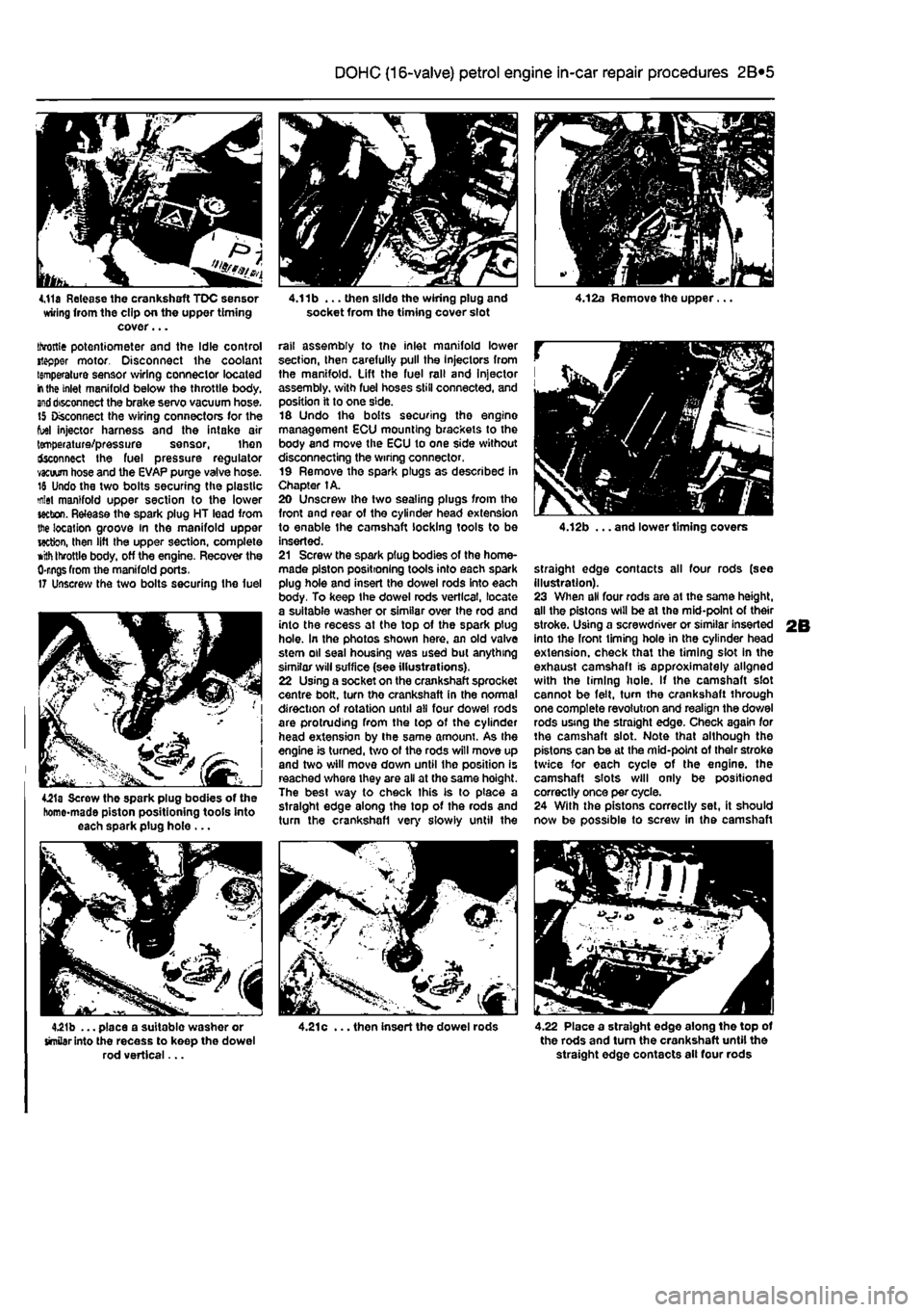
Removal 5 Disconnect the battery negative terminal (refer to Disconnecting the battery in the Reference Section of Ihis manual). 6 Remove the auxiliary drivebelt(s) as described In Chapter 1A. 7 Remove the air cleaner, Inlet air duct and resonator as desenbed In Chapter 4B. 8 Undo the three bolts and remove the crankshaft pulley from the sprocket (see illustration). 9 Undo the retaining bolt In the centre of the lower liming cover (see illustration). 10 Undo tho uppor timing cover upper retaining bolt, and the rear retaining bolt located above the alternator (see illustration). 11 Release the crankshaft TDC sensor wiring from the clip on the upper timing cover, then withdraw the cover slightly and slide Ihe wiring plug and socket from the liming cover slot (see illustrations). 12 Release the TDC sensor wiring from the periphery ol the upper and fower timing covers and remove both covers (see Illustrations). 13 Free the accelerator inner cable from the throttle cam, remove the outer cable spring dip, then pull the outer cable out from its mounting bracket rubber grommet. 14 From the side of the throttle body, disconnect the wiring connectors from the
Page 65 of 225
2B*5 DOHC (16-valve) petrol engine in-car repair procedures
4.11a Release the crankshaft TDC sensor wiring from the clip on the upper timing cover... throttle potentiometer and the Idle control stepper motor. Disconnect the coolant temperature sensor wiring connector located
in
the inlet manifold below the throttle body,
end
disconnect the brake servo vacuum hose. 15 Disconnect the wiring connectors for the fuel injector harness and the intake air temperature/pressure sensor, then fcconnect the fuel pressure regulator vacuum hose and the EVAP purge valve hose. 18 Undo the two bolts securing the plastic mlet manifold upper section to the lower section. Release the spark plug HT lead from the location groove in the manifold upper wctton, then lift the upper section, complete
»ith
throttle body, off the engine. Recover the 0-rngs from the manifold ports. 17 Unscrew the two bolts securing the fuel
4£1a Screw the spark plug bodies of the homo-made piston positioning tools into each spark plug hole ...
4.21b ... place a suitable washer or similar into the recess to keep the dowel rod vertical...
4.11b ... then slide the wiring plug and socket from the timing cover slot
rail assembly to the inlet manifold lower section, then carefully pull the Injectors from the manifold. Lift the fuel rail and Injector assembly, with fuel hoses still connected, and position it to one side. 16 Undo the bolts securing the engine management ECU mounting brackets to the body and move the ECU to one side without disconnecting the wiring connector. 19 Remove the spark plugs as described in Chapter 1A. 20 Unscrew the two sealing plugs from the front and rear of the cylinder head extension to enable the camshaft locking tools to be inserted. 21 Screw the spark plug bodies of the home-made piston positioning tools into each spark plug hole and insert the dowel rods into each body. To keep the dowel rods vertical, locate a suitable washer or similar over Ihe rod and into the recess at the top of the spark plug hole. In the photos shown here, an old valve stem oil seal housing was used but anything similar will suffice (see illustrations). 22 Using a socket on the crankshaft sprocket centre bolt, turn the crankshaft in the normal direction of rotation until all four dowel rods are protruding from the top of the cylinder head extension by the same amount. As the engine is turned, two of the rods will move up and two will move down until the position is reached where they are all at the same hoight. The best way to check this is to place a straight edge along the top of the rods and turn the crankshafl very slowly until the
4.21c ... then insert the dowel rods
4.12b ... and lower timing covers
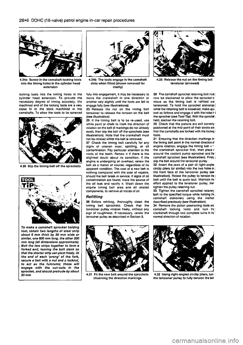
straight edge contacts all four rods (see illustration). 23 When all four rods are at the same height, all the pistons will be at the mid-point of their stroke. Using a screwdriver or similar inserted into the front timing hole in the cylinder head extension, check that the timing slot in the exhaust camshaft is approximately aligned with the liming hole. If the camshaft slot cannot be felt, turn the crankshaft through one complete revolution and realign the dowel rods using the straight edge. Check again for the camshaft slot. Note that although the pistons can be at the mid-point of their stroke twice for each cycle of the engine, the camshaft slots will only be positioned correctly once per cycle. 24 With the pistons correctly set, it should now be possible to screw in the camshaft
4.22 Place a straight edge along the top of the rods and turn the crankshaft until the straight edge contacts ail four rods
Page 66 of 225
2B*6 DOHC (16-valve) petrol engine in-car repair procedures
4.24a Scrow in the camshaft locking tools into the timing holes in the cylinder head extension
locking tools Into the timing holes in the cylinder head extension. To provide the necessary degree of timing accuracy, the machined end of the locking tools are a very close fit in the slots machined in the camshafts. To allow the tools to be screwed
4.26 Slip the timing belt off the sprockets
To make a camshaft sprocket holding tool, obtain two lengths of steel strip about 6 mm thick by 30 mm wide or simitar, one 600 mm long, the other
200
mm long (all dimensions approximate). Bolt the two strips together to form a forked end, leaving the bolt slack so that the shorter sfrfp can pivot freely. At the end of each 'prong' of the fork, secure a bolt with a nut and a locknut, to act as the fulcrums; these will engage with the cut-outs In the sprocket, and should profrude by about 30 mm
4.24b The tools engage in tho camshaft slots when fitted (shown removed for clarity)
fully into engagement, it may be necessary to move the crankshaft In one direction or another very slightiy until the tools are felt to engage fully (see illustrations). 25 Release tho nut on the timing belt tensioner to release the tension on the belt (see illustration) 26 II the timing belt is to be re-used, use white paml or chalk to mark the direction of rotation on the belt (if markings do not already exist), then slip the belt off the sprockets (see illustration). Note that the crankshaft must not be rotated whilst the belt is removed. 27 Check the timing belt carefully for any signs of uneven wear, splitting, or oil contamination. Pay particular attention to the roots ol the teeth. Renew it If there is the slightest doubt about its condition. If the engine is undergoing an overhaul, renew the belt as a matter of course, regardless of its apparent condition. The cost ol a new bett is nothing compared with the cosi of repairs, should the belt break in service. If signs of oil contamination are found, trace the source of the oil leak 8nd rectify it. Wash down the engme timing belt area and all related components, to remove all traces of oil,
Refitting 28 Before refilling, thoroughly clean the liming bell sprockets. Check that Ihe tensioner pulley rotates freely, without any sign of roughness. If necessary, renew Ihe tensioner pulley as described in Section 5,
4.31 Fit the new belt around the sprockots observing the direction markings
4.25 Release the nut on the timing belt tensioner (arrowed)
29 The camshaft sprocket retaining bolt mutt; now be slackened to allow the sprocket Ic move as the timing bell Is refitted una tensioned. To hold the sprocket stationary^ while the retaining bolt is loosened, make upi. tool os follows and engage
>t
with the holes ^ i the sprocket (see Tool Tip). With the sprocket. held, slacken the retaining bolt. 30 Check that the pi6tons are still correct positioned at ihe mid-point of their stroke are that the camshafts are locked with the lockup: tools. 31 Ensuring that the direction markings on the timing belt point in the normal direction
cf
engine rotation, engage the Umlng belt vr* Ihe crankshaft sprocket first, then placed around the coolant pump sprocket and tte: camshaft sprocket (see Illustration). Rnaii>; slip the belt around the tensioner pulley. 32 Insert the jaws of a pair of right-angleo clrclip pliers (or similar) into Ihe two holes on; Ihe front face of the tensioner pulley (sec Illustration). Rotate the pulley to tension Ihj; belt until the belt Is quite taut. Maintain thr effort applied to the tensioner pulley. JM* tighten the pulley retaining nut. 33 Tighten the camshaft sprocket retains; bolt to the specified torque while holding th?; camshaft stationary using the method described previously (see Illustration). 34 Remove the piston positioning tools arc camshaft locking tools and turn In*; crankshaft through two complete turns In the normal direction of rotation,
4.32 Using right-angled clrclip pliers, turn the tensioner pulley to fully tension the bell
Page 67 of 225
2B*7 DOHC (16-valve) petrol engine in-car repair procedures
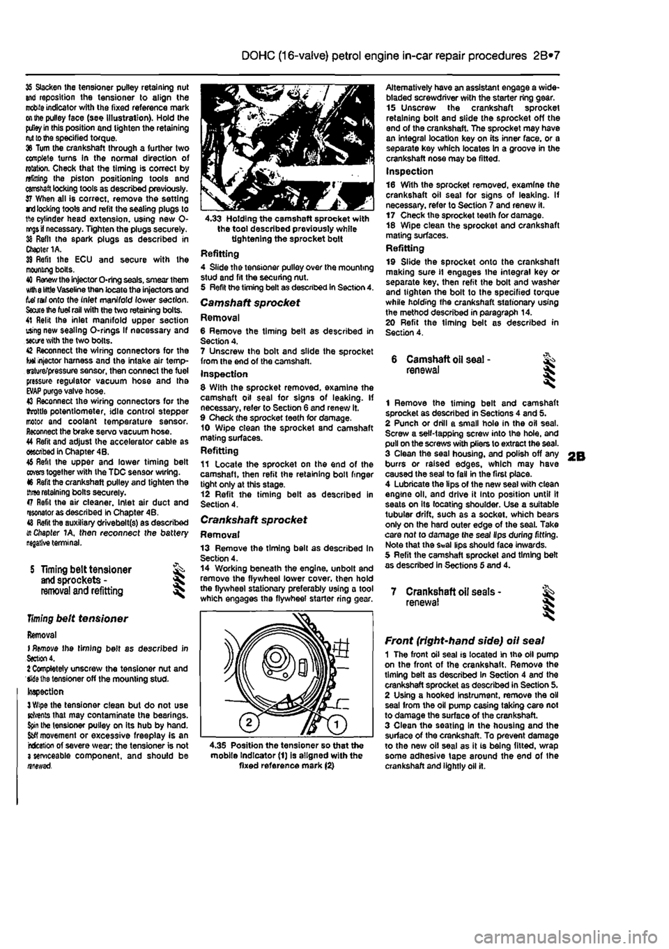
35 Slacken the tensioner pulley retaining nut and reposition the tensioner to align the
mobile
indicator with the fixed reference mark
on the
pulley face (see illustration). Hold the
pdley in
this position and tighten the retaining
nut to the
specified torque. 36 Turn the crankshaft through a further two complete turns In the normal direction of rotation. Check that the timing is correct by alining Ihe piston positioning tools and
camshaft
locking tools as described previously. 37 When all is correct, remove the setting rri
locking
tools and refit the sealing plugs to 1ft© cylinder head extension, using new 0-
nr^s if
necessary. Tighten the plugs securely. 38 Refit the spark plugs as described in Chapter 1A. 39 Refit Ihe ECU and secure with Ihe mooning bolts. 40
Renew the
injector O-ring seals, smear them Kith
8 little
Vaseline then locate the injectors and tef rail onto the inlet manifold lower section.
Saute Ihe fuel rail
with the two retaining bolts. 41 Relit the inlet manifold upper section using new sealing O-rlngs If necessary and
sectre
with the two bolts. 42 Reconnect the wiring connectors for the tot injector harness and the intake air temp-erature/pressure sensor, then connect the fuel pressure regulator vacuum hose and tha
EVAP
purge valve hose. 43 Reconnect the wiring connectors for the ihrottls potentiometer, idle control stepper motor and coolant temperature sensor. Reconnect the brake servo vacuum hose. 44 Refit and adjust the accelerator cable as described in Chapter 4B. 46 Refit the upper and lower timing belt
covers
together with the TDC sensor wiring. 46 Refit the crankshaft pulley and tighten the
three
retaining bolts securely. 47 Refit the air cleaner. Inlet air duct and resonator as described in Chapter 4B. 48
Refit
tha auxiliary drivebelt(s) as described i/t Chapter 1A, then reconnect the battery
S Timing belt tensioner
and
sprockets -
removal
and refitting
Timing
belt tensioner
Removal I
Remove
the timing belt as described in
Section
4. 1 Completely unscrew the tensioner nut and Wiethe tensioner off the mounting stud-Inspection
3 Wipe
the tensioner clean but do not use Kfrents that may contaminate the bearings.
Spin
the tensioner pulley on its hub by hand.
Sfcfl
movement or excessive freeplay is an rcfceticn of severe wear: the tensioner is not 3 serviceable component, and should be nnewsd.
4.33 Holding the camshaft sprocket with the tool described previously while tightening the sprocket bolt Refitting 4 Slide the tensioner pulley over the mounting stud and fit the securing nut. 5 Refit the timing belt as described in Section 4. Camshaft sprocket Removal 6 Remove the timing belt as described in Section 4. 7 Unscrew the bolt and slide the sprocket from the end of the camshaft. Inspection 8 With the sprocket removed, examine the camshaft oil seal for signs of leaking. If necessary, refer to Section 6 and renew it. 9 Check the sprocket teeth for damage. 10 Wipe clean the sprocket and camshaft mating surfaces. Refitting 11 Locate the sprocket on the end of the camshaft, then refit the retaining boll finger tight only at this stage. 12 Refit the timing belt as described in Section 4.
Crankshaft sprocket Removal 13 Remove the timing bell as described In Section 4. 14 Working beneath the engine, unbolt and remove the flywheel lower cover, then hold the flywheel stationary preferably using a tool which engages the flywheel starter ring
<
Alternatively have an assistant engage a wide-bladed screwdriver with the starter ring gear. 15 Unscrew the crankshaft sprocket retaining bolt and slide the sprocket off the end of the crankshaft. The sprocket may have an integral location key on its inner face, or a separate key which locates In a groove in the crankshaft nose may be fitted. Inspection 16 With the sprocket removed, examine the crankshaft oil seal for signs of leaking. If necessary, refer to Section 7 and renew it. 17 Check the sprocket teeth for damage. 18 Wipe clean the sprocket and crankshaft mating surfaces. Refitting 19 Slide the sprocket onto the crankshaft making sure
11
engages the integral key or separate key, then refit the bolt and washer and tighten the bolt to the specified torque while holding the crankshaft stationary using the method described in paragraph 14. 20 Refit the timing belt as described in Section 4.
6 Camshaft
oil
seal -renewal
1 Remove the timing belt and camshaft sprocket as described in Sections 4 and 5. 2 Punch or drill a small hole in the oil seal. Screw a self-tapping screw into the hole, and pull on the screws with pliers to extract the seal. 3 Clean the seal housing, and polish off any burrs or raised edges, which may have caused the seal to fall in the first place. 4 Lubricate the lips of the new seal with clean engine oil, and drive it into position until It seats on its locating shoulder. Use a suitable tubular drift, such as a socket, which bears only on the hard outer edge of the seal. Take care nof to damage the seal lips during fitting. Note that the Seal lips should face inwards. 5 Refit the camshaft sprocket and timing belt as described in Sections 5 and 4.
7 Crankshaft oil seats -renewal I
4.35 Position the tensioner so that the mobile Indicator (1) is aligned with the fixed reference mark (2)
Front (right-hand side) oil seal 1 The front oil seal is located in the oil pump on the front of the crankshaft. Remove the timing belt as described in Section 4 and the crankshaft sprocket as described in Section 5. 2 Using a hooked Instrument, remove the oil seal from the oil pump casing taking care not to damage the surface of the crankshaft. 3 Clean the seating in the housing and the surface of the crankshaft. To prevent damage to the new oil seal as it is being fitted, wrap some adhesive tape around the end of the crankshaft and lightly oil it.
Page 68 of 225
2B*8 DOHC (16-valve) petrol engine in-car repair procedures
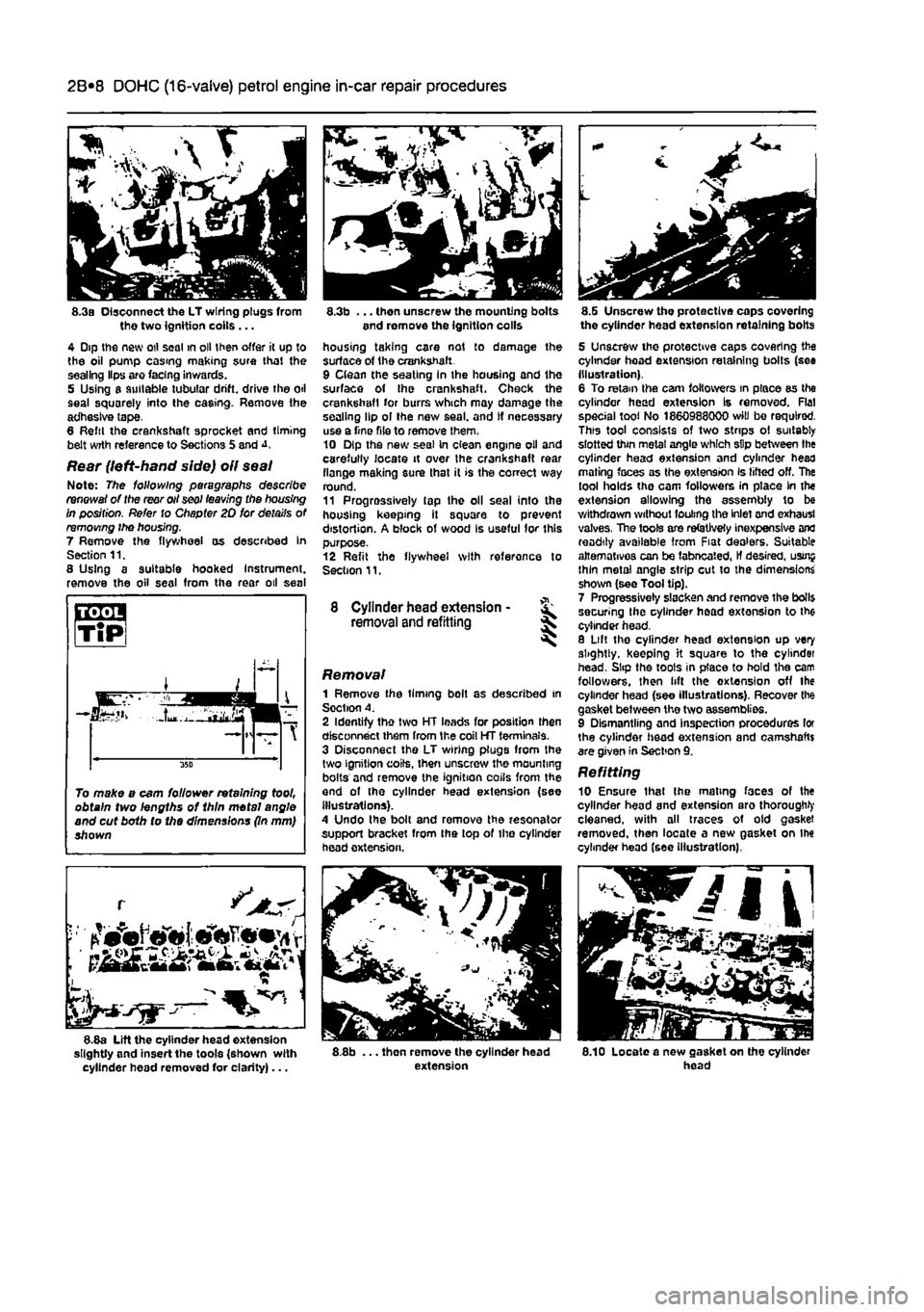
8.3a Disconnect the LT wiring plugs from the two Ignition coils ... 4 Dip the new oil seal in oil then offer it up to the oil pump casing making sure that the sealing Hps are facing inwards. 5 Using a suitable tubular drift, drive the oil seal squarely into the casing. Remove the adhesive tape, 8 Reftl the crankshaft sprocket and timing belt wrth reference to Sections 5 and
Rear (left-hand side) oil seal Note: The following paragraphs describe renewal of the rear oil seal leaving the housing in position. Refer to Chapter 20 for details of removing ihe housing. 7 Remove the flywheel as described In Section 11. 8 Using a suitable hooked Instrument, remove the oil seal from the rear oil seal
L •
~ 1 8.8a Lift the cylinder head extension slightly and insert the tools {shown with cylinder head removed for clarity)...
8.3b ... then unscrew the mounting bolts end romove the ignition colls housing taking care not to damage the surface of the crankshaft. 9 Clean the seating In the housing and the surface of Ihe crankshaft. Check the crankshaft for burrs which may damage the sealing lip ol Ihe new seal, and If necessary use a Tine file to remove them. 10 Dip the new seal In clean engine oil and carefully locate it over Ihe crankshaft rear flange making sure that it is the correct way round. 11 Progressively tap the oil seal into the housing keeping it square to prevent distortion. A block of wood Is useful for this purpose. 12 Refit the flywheel with reference to Section 11,
8 Cylinder head extension -removal and refitting ^
Removal 1 Remove the timing bolt as described in Soction A. 2 Identify the two HT leads for position then disconnect them from the coil HT terminals. 3 Disconnect the LT wiring plugs from the two ignition coils, then unscrew the mounting bolts and remove the ignition coils from the and of the cylinder head extension {see illustrations). A Undo the bolt and remove the resonator support bracket from Ihe top of the cylinder head extension,
8.8b ... thon remove the cylinder head extension
8.G Unscrew tho protective caps covering the cylinder head extension retaining bolts
5 Unscrew the protective caps covering the cylinder head extension retaining bolts (see Illustration). 6 To retain the cam followers in place as the cylinder head extension Is removed. Flat special tool No 1860988000 will bo required. This tool consists of two strips ol suitably slotted thin metal angle which sDp between the cylinder head extension and cylinder head mating faces as the extension Is lifted off. The tool holds the cam followers in place in the extension allowing the assembly to be withdrawn without fouling the Inlet and exhausl valves, The tools are refetJvety inexpensive and readily available from Fiat dealers. Suitable alternatives can be fabneated, If desired, usrnj thin metal angle strip cut to the dimensions shown (see Tool tip). 7 Progressively slacken and remove the boll$ securing the cylinder head extension to the cylinder head. 8 Lilt tho cylinder head extension up very slightly, keeping it square to the cylindei head. Slip the toots in place to hold the cam followers, then lift the extension off the cylinder head (see illustrations). Recover the gasket between the two assemblies. 9 Dismantling and Inspection procedures lor the cylinder head extension and camshafts are given in Section 9. Refitting 10 Ensure thai Ihe mating faces of the cylinder head and extension aro thorough^ cleaned, with all traces of old gasket removed, then locate a new gasket on Ihe cylinder head (see Illustration).
8.10 Locate a new gasket on the cylinder head
To make a cam follower retaining tool, obtain two lengths of 1hln metal angle and cut both to the dimensions (In mm) shown
Page 69 of 225
2B*9 DOHC (16-valve) petrol engine in-car repair procedures
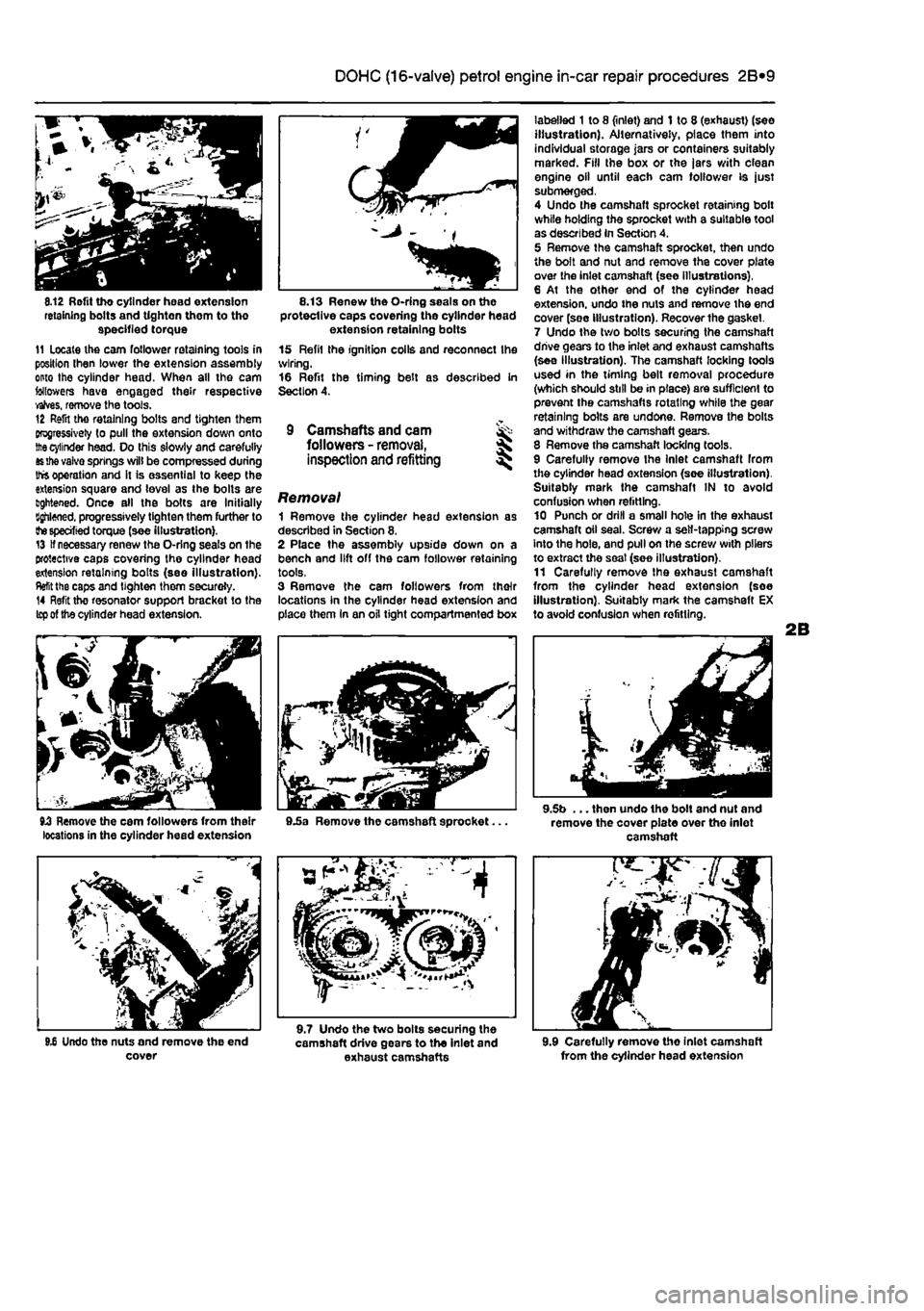
8.12 Rofit tho cylinder head extension retaining bolts and tighten them to tho specified torque 11 Locate the cam follower retaining tools in position Ihen lower the extension assembly onto the cylinder head. When all the cam followers have engaged their respective valves, remove the tools. 12 Refit tho retaining bolts and tighten them progressively to pull the extension down onto
the
cylinder head. Do this slowly and carefully
as the
vaivo springs will be compressed during Ihfs operation and it is essential to keep the extension square and level as the bolts are lightened. Once all the bolts are Initially Bghloned. progressively tighten them further to
the specified
torque (see illustration). 13 If necessary renew the O-rlng seals on the protective caps covering the cylinder head extension retaining bolts (see illustration).
Refit
the caps and tighten them securoly. 14 Refit the resonator support bracket to the
Icp of
the cylinder head extension.
8.13 Renew the O-ring seals on the protective caps covering the cylinder head extension retaining bolts 15 Refil the ignition coils and reconnect Ihe wiring. 16 Refit the timing belt as described in Section 4.
9 Camshafts and cam ^ followers -
removal,
S inspection and refitting ^
Removal 1 Remove the cylinder head extension as described in Section 8. 2 Place the assembly upside down on a bench and lift off the cam follower retaining tools, 3 Remove the cam followers from their locations In the cylinder head extension and place them In an oil tight compartmented box
labelled 1 to 8 (inlet) and 1 to 8 (exhaust) (see illustration). Alternatively, place them into individual storage jars or containers suitably marked. Fill the box or the jars with clean engine oil until each cam follower is just submerged, 4 Undo the camshaft sprocket retaining bolt while holding the sprocket with a suitable tool as described In Section 4. 5 Remove the camshaft sprocket, then undo the bolt and nut and remove the cover plate over the inlet camshaft (see Illustrations), 6 At the other end of the cylinder head extension, undo the nuts and remove the end cover (soe Illustration). Recover the gasket. 7 Undo the two bolts securing the camshaft drive gears to the inlet and exhaust camshafts (see illustration). The camshaft locking tools used in the timing belt removal procedure (which should still be in place) are sufficient to prevent the camshafts rotating while the gear retaining bolts are undone. Remove the bolts and withdraw the camshaft gears. 8 Remove the camshaft locking tools. 9 Carefully remove the Inlet camshaft from the cylinder head extension (see illustration). Suitably mark the camshaft IN to avoid confusion when refitting. 10 Punch or drill a small hole in the exhaust camshaft oil seal. Screw a self-tapping screw into the hole, and pull on the screw with pliers to extract the seat (soe illustration). 11 Carefully remove Ihe exhaust camshaft from the cylinder head extension (soe illustration). Suitably mark the camshaft EX to avoid confusion when refitting.
JJ Remove the cam followers from their 9.5a Remove the camshaft sprocket... locations in the cylinder head extension
9.5b ... then undo the bolt and nut and remove the cover plate over tho inlet camshaft
9.6 Undo the nuts and remove the end cover
9.7 Undo the two bolts securing the camshaft drive gears to the inlet and exhaust camshafts 9.9 Carefully remove tho Inlet camshaft from the cylinder head extension
Page 70 of 225
2B*10 DOHC (16-valve) petrol engine in-car repair procedures
9.10 Extract the exhaust camshaft oil seal...
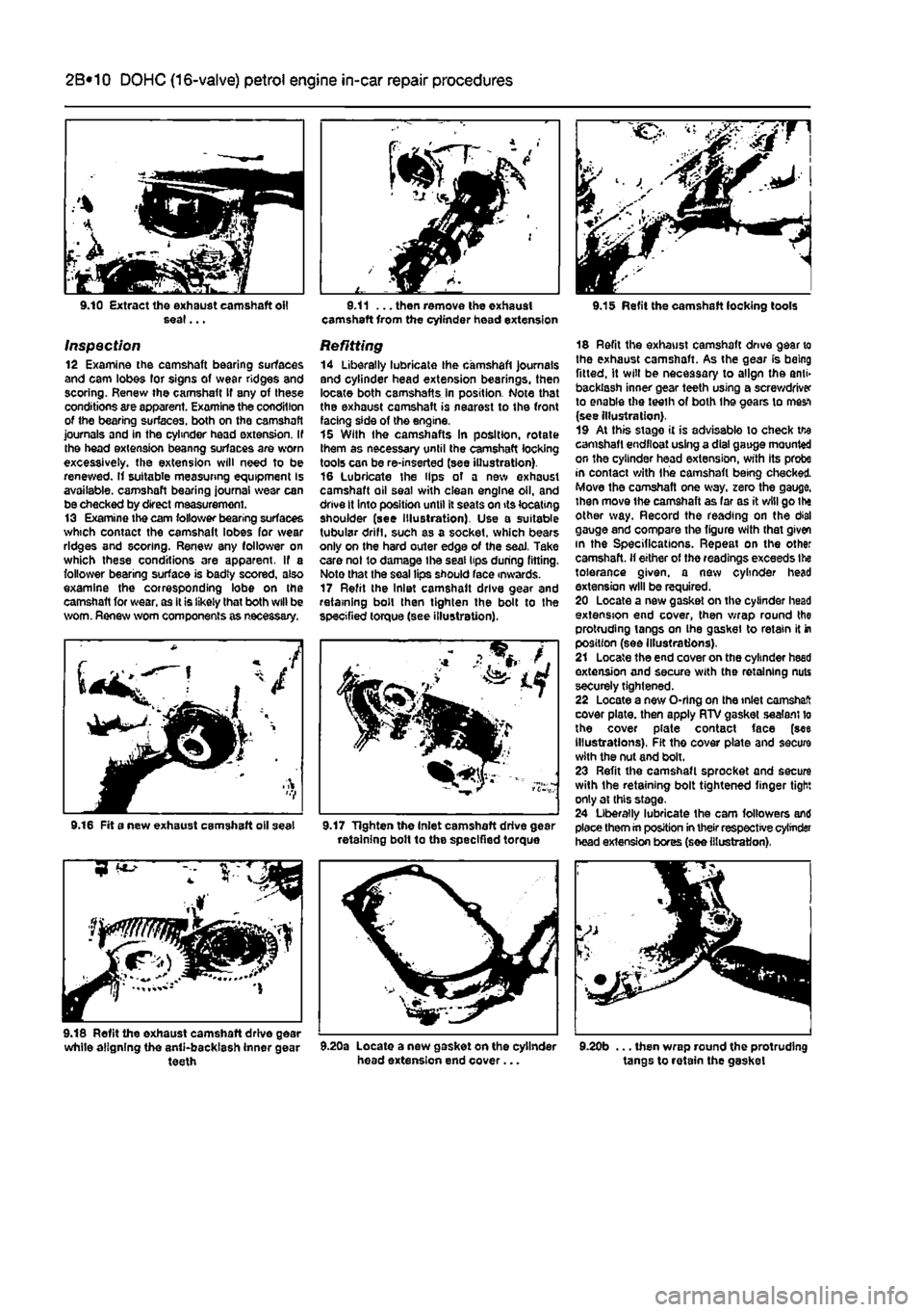
Inspection 12 Examine the camshaft bearing surfaces and cam lobes for signs of wear ridges and scoring. Renew ihe camshaft If any of these conditions are apparent. Examine the condition of the bearing surfaces, both on the camshaft journals and in the cylinder head extension. If the head extension beanng surfaces are worn excessively, the extension will need to be renewed. If suitable measuring equipment Is available, camshaft bearing journal wear can be checked by direct measurement. 13 Examine the cam follower bearing surfaces which contact the camshaft lobes for wear ridges and scoring. Renew any follower on which these conditions are apparent. If a follower bearing surface is badty scored, also examine the corresponding lobe on the camshaft for wear, as it is likely that both will be worn. Renew worn components as necessary.
9.11 ... then remove the exhaust camshaft from the cylinder head extension
Refitting 14 Liberally lubricate the camshaft journals and cylinder head extension bearings, then locate both camshafts in position Note that the exhaust camshaft is nearest to the front facing side of the engine. 15 With the camshafts In position, rotate them as necessary until the camshaft locking tools can be re-inserted (see illustration). 16 Lubricate the Hps of a new exhaust camshaft oil seal with clean engine oil, and drive It into position until it seats on its locating shoulder (see Illustration). Use a suitable tubular drifl, such as a socket, which bears only on the hard outer edge of the seaJ. Take care not to damage the seal lips during fitting. Noto that the seal lips should face inwards. 17 Refit the Inlet camshaft drive gear and retaining boll then tighten the bolt to the specified torque (see illustration).
9.16 Fit a new exhaust camshaft oil seal M7 Tighten the Inlet camshaft drive gear retaining bolt to the specified torque
9.15 Refit the camshaft locking tools
18 Refit the exhaust camshaft drive gear to the exhaust camshaft. As the gear is being fitted, It will be necessary to align the anti» backlash inner gear teeth using a screwdriver to enable the teeih of both Ihe gears to mes-i (see Illustration). 19 At this stage it is advisable lo check tie camshaft endfloat using a dial gauge mounted on the cylinder head extension, with its probe in contact with Ihe camshaft being checked Move the camshaft one way. zero the gauge, then move the camshaft as far as it will go ihe other way. Record the reading on the dial gauge and compare the figure with that given in the Specifications. Repeat on the other camshaft. If either of the readings exceeds the tolerance given, a new cylinder head extension will be required. 20 Locate a new gasket on the cylinder head extension end cover, then wrap round the protruding tangs on Ihe gasket to retain it in position (see Illustrations). 21 Locate the end cover on the cylinder heed extension and secure with the retaining nuts securely tightened. 22 Locate a new O-ring on the inlet camshaft cover plate, then apply RTV gasket sealant lo the cover plate contact face (see Illustrations), Fit tho cover plate and secure with the nut and bolt. 23 Refit the camshaft sprocket and secure with the retaining bolt tightened finger tight only at this stage. 24 Liberally lubricate the cam followers and piece them in position in their respective cylinder head extension bores (see illustration),
9.18 Refit the exhaust camshaft drive gear white aligning the anti-backlash Inner gear teeth 9.20a Locate a new gasket on the cylinder head extension end cover... 9.20b ... then wrap round the protruding tangs to retain the gaskel