Identification FIAT PUNTO 1998 176 / 1.G Workshop Manual
[x] Cancel search | Manufacturer: FIAT, Model Year: 1998, Model line: PUNTO, Model: FIAT PUNTO 1998 176 / 1.GPages: 225, PDF Size: 18.54 MB
Page 4 of 225
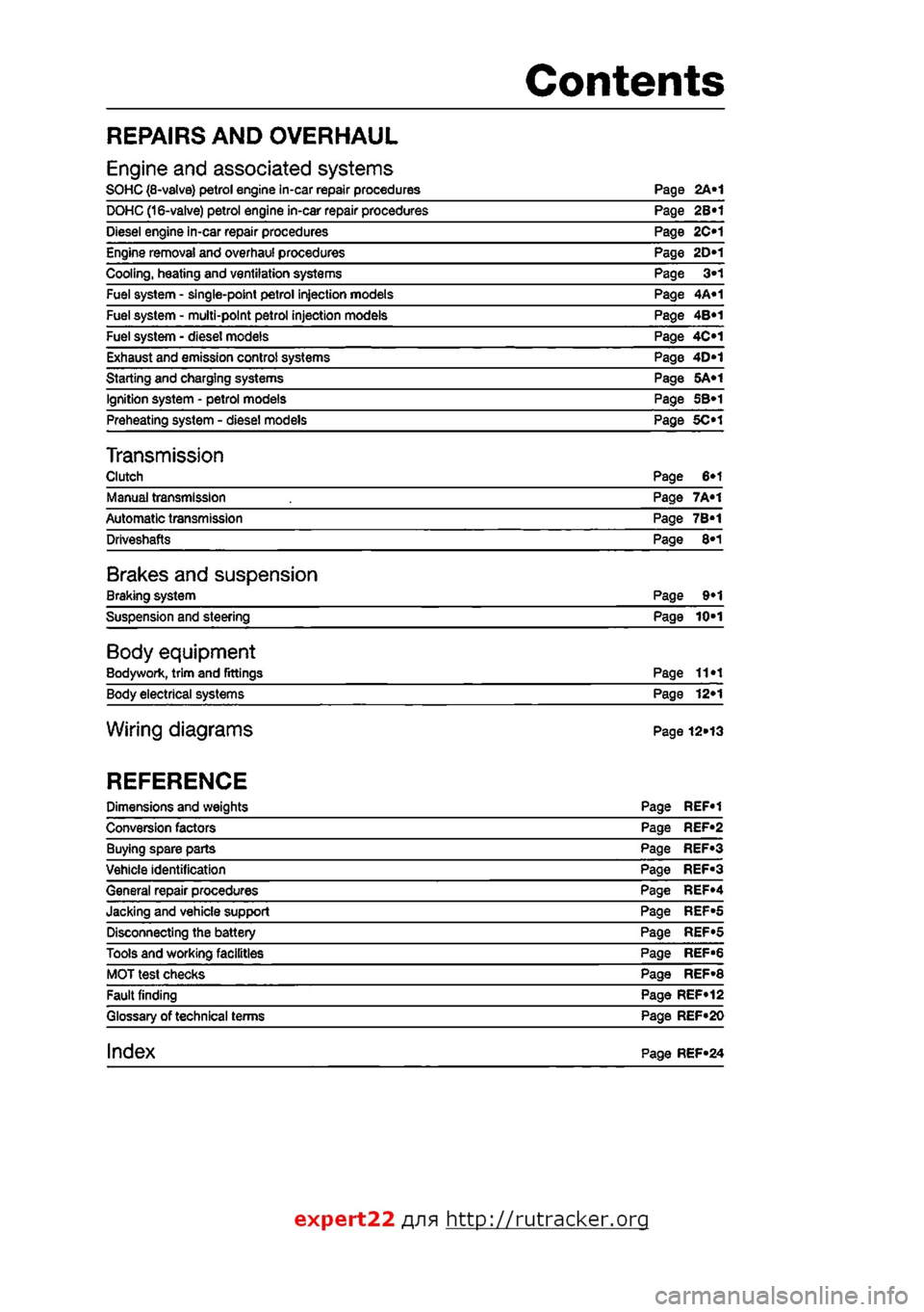
Contents
REPAIRS AND OVERHAUL
Engine and associated systems SOHC (8-valve) petrol engine in-car repair procedures Page 2A«1 DOHC (16-valve) petrol engine in-car repair procedures Page 2B«1 Diesel engine in-car repair procedures Page 2C«1 Engine removal and overhaul procedures Page 2D«1 Cooling, heating and ventilation systems Page 3»1 Fuel system - single-point petrol injection models Page 4A«1 Fuel system - multi-point petrol injection models Page 4B«1 Fuel system - diesel models Page 4C»1 Exhaust and emission control systems Page 4D*1 Starting and charging systems Page SA«1 Ignition system - petrol models Page SB«1 Preheating system - diesel models Page 5C>1
Transmission Clutch Page 6»1 Manual transmission Page 7A«1 Automatic transmission Page 7B*1 Driveshafts Page 8*1
Brakes and suspension Braking system Page 9*1 Suspension and steering Page 10-1
Body equipment Bodywork, trim and Fittings Page 11«1 Body electrical systems Page 12*1
Wiring diagrams Page 12»13
REFERENCE
Dimensions and weights Page REF«1 Conversion factors Page REF*2 Buying spare parts Page REF»3 Vehicle identification Page REF«3 General repair procedures Page REF«4 Jacking and vehicle support Page REF»5 Disconnecting the battery Page REF«5 Tools and working facilities Page REF-6 MOT test checks Page REF»8 Fault finding Page REF»12 Glossary of technical terms Page REF»20
index Page REF»24
expert22 rjijr http://rutracker.org
Page 13 of 225
o*i2 Weekly checks
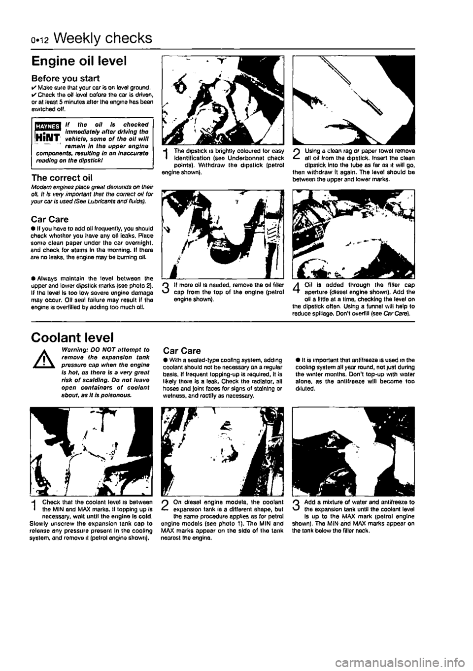
Engine oil level
Before you start • Make euro that your cor is on level ground. • Check ihe oil level oefore ihe cor is driven, or at least 5 minutes alter the engine has been switched off.
HHifffl If tho oil Is checked rTf"™^ Immediately after driving the IHlAIT vehicle,
some
of the oil will " remain In the upper engine components, resulting in on inaccurate reading on the dipstick!
The correct oil Modern engines place great demands on their oil. It Is very important that the correct oil for your car is used
Car Care • If you have to add oil frequently, you should check whother you have any oil leaks. Place some clean paper under the car overnight, and check for stains In the morning. If there are no leaks, the engine may be burning oil.
• Always maintain the level between the upper and lower dipstick marks (see pholo 2). If Ihe level Is too low
sqvoio
engine damage may oecur. Oil seal failure may result if tho engine is overfilled by adding too much oil.
I
Tho dipstick is brightly coloured for easy identification (seo Under bonnet check points). Withdraw the dipstick (petrol engine shown).
3
If more oil is needed, remove the oil filler cap Irom the top of the ongine (petrol engine shown).
SI i J
2
Using a clean rag or paper towel remove all oil from the dipstick. Insert the clean dipstick into the tube as far as it will go, then withdraw it again. The level should be between the upper and lower marks.
4
Oil Is added through the filler cap aperture (diesel engine shown). Add the oil a little at a time, checking the level on the dipstick often. Using a funnel will help to reduce spillage. Don't overfill (see Car Care).
Coolant level
A
Warning: DO NOT attempt to remove the expansion tank pressure cap when the engine is hot, as there is a very great risk of scalding. Do not leave open containers of coo/ant about, as It is poisonous.
Car Care • With a sealed-type cooling system, adding coolant should not be necessary on a regular basis. If frequent topping-up is required, it is likely there Is a leak. Check the radiator, all hoses and Joint faces for signs of staining or wetness, and roctify as necessary.
• It is important that antifreeze is used in the cooling system all year round, not just during the winter months. Don't top-up with water alone, as the antifreeze will become too diluted.
H Check that the coolant level is between I the MIN and MAX marks, il topping up is necessary, wait until tho engine is cold. Slowly unscrew the expansion tank cap to release any pressure present in the cooling system, and remove it (petrol engine shown).
2
On diesel engine models, Ihe ooolant expansion tank is a different shape, but Ihe same procedure applies as for petrol engine models (see photo 1). Tho MlN and MAX marks appear on the side of tlie tank neorosl the engine.
3
Add a mixture of water and antifreeze to the expansion tank until the coolant level is up to the MAX mark (petrol engine shown), The MIN and MAX marks appear on the tank below the filler neck.
Page 51 of 225
2A«1
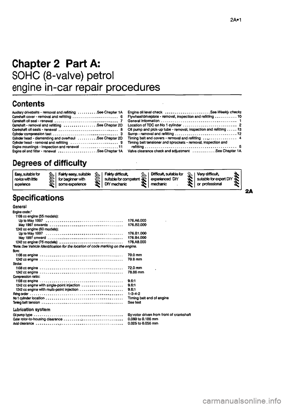
Chapter 2 Part A:
SOHC (8-valve) petrol
engine in-car repair procedures
Contents
Auxiliary drivebelts • removal and refitting See Chapter 1A Gamstaft cover - removal and refitting 6 Camshaft oil seal - renewal 7 Camshaft • removal and refitting See Chapter 20 Crankshaft oil seals - renewal 8 Cylinder compression test 3 Cylinder head - dismantling and overhaul See Chapter 20 Cylinder head - remove] and refitting 9 Engine mountings - Inspection and renewal 11 Engine oil and filter • renewal See Chapter 1A
Degrees of difficulty
Engine oil level check See Weekiy checks Flywheel/driveplate • removal, inspection and refitting 10 General Information 1 Location of TOC on No 1 cylinder 2 Oil pump and pick-up tube - removal, inspection and refitting 13 Sump • removal and refitting 12 Timing belt and covers • removal and refitting .. 4 Timing belt tensioner and sprockets - removal, inspection and refitting 5 Vafve clearance check and adjustment See Chapter 1A
Easy, suitable (or twics with little |g experience ^
Fairty easy, suitable jk for beginner with & some experience ^
Fatrty difficult, ^ suitable for competent ^ CKYmechanic ^
Difficult, suitable for ^ experienced DIY « mechanic ^
Veiy difficult, ^ aiitabte for expert DIY « or professional
Specifications
General Engine code:' 1108 cc engine (55 models): Up to May 1997 176.A6.000 May 1d97 onwards • . 176.B2.000 1242 cc engine (60 models): Up to May 1997 176.B1.000 May 1997 onward 176.B4.000 1242 cc engine (75 modete) 176.A8.000
•Note:
See Vehicle Identification for the location of code marking on the engine. 8cre: 11O0OC engine 70.0 mm 1242 cc engine 70.8 mm Stroke: 1108 cc engine 72.0 mm 1242 cc engine 78.86 mm Compression ratio: 1108 cc engine 9.6:1 1242 cc engine with single-point injection 9.6:1 1242 cc engine with multi-point injection 9.8:1 Rrlng order 1-3-4-2
No 1
cylinder location Timing belt end of engine
TnUng
belt tension See text
Lubrication system
Oil
pump type By-rotor driven from front of crankshaft Outer rotor-to-housing clearance 0.080to0.186mm
Axial
clearance 0.025 to 0.056 mm
Page 61 of 225
2B»1
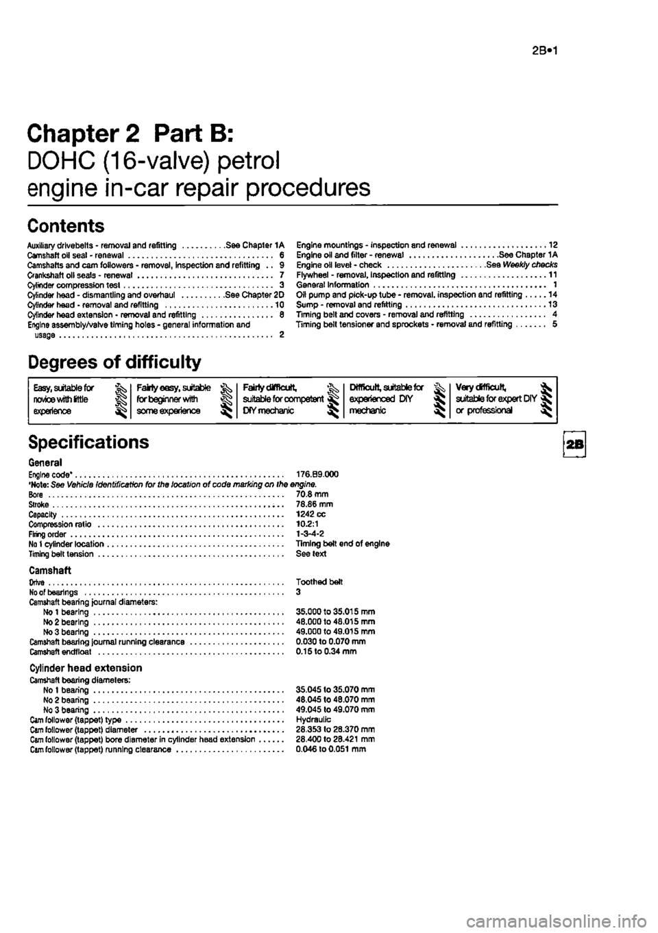
Chapter 2 Part B:
DOHC (16-valve) petrol
engine in-car repair procedures
Contents
Auxiliary drlvebelts - removal and refitting See Chapter 1A Camshaft oil seal - renewal 6 Camshafts and cam followers - removal, inspection and refitting .. 9 Crankshaft oil seals • renewal 7 Cylinder compression test 3 Cylinder head - dismantling and overhaul See Chapter 2D Cylinder head • removal and refitting 10 Cylinder head extension • removal and refitting 8 Engine assembly/Valve timing holes - general information and usage 2
Engine mountings - inspection and renewal 12 Engine oil and filter - renewal See Chapter 1A Engine oil level - check See Weekly checks Flywheel - removal, Inspection and refitting 11 General Information 1 Oil pump and pick-up tube - removal, inspection and refitting 14 Sump - removal and refitting 13 Timing belt and covers - removal and refitting 4 Timing belt tensioner and sprockets • removal and refitting 5
Degrees of difficulty
Easy,
sitable
for
J; Fairly
easy,
suitable Fairtydifflcutt, ^
Difficult,
aitabtefcr Very
difficult,
^ nwice
wim
(ttls for beginner with £
suitable
for competent KYmechanic ^ experienced DIY > suitable
for
expert DIY« experience
some
experience £
suitable
for competent KYmechanic ^ mechanic > or professional ^
Specifications
General Engine code* 176.09.000 •Note: See Vehicle Identification for the location of code marking on the engine. Bore 70.8 mm Stroke 78.86 mm Capacity 1242 cc Compression ratio 10.2:1 Firing order 1-3-4-2 No
1
cylinder location Timing belt end of engine Timing belt tension See text
Camshaft Orlve Toothed belt
No
of bearings 3 Camshaft bearing journal diameters: Ho
1
bearing 35.000 to 35.015 mm
Mo
2 bearing 48.000 to 48.015 mm No 3 bearing 49.000 to 49.015 mm Camshaft bearing Journal running clearance 0.030 to 0.070 mm Camshaft endfloat 0.15 to 0.34 mm
Cylinder head extension Camshaft bearing diamelers: No
1
bearing 35.045 to 35.070 mm No 2 bearing 48,045 to 48.070 mm No 3 bearing 49.045 to 49.070 mm
Cam
follower (tappet) type Hydraulic
Cam
follower (tappet) diameter 28.353 to 28.370 mm
Cam
follower (tappet) bore diameter in cylinder head extension 28.400 to 28.421 mm
Cam
follower (tappet) running clearance 0.046 to
0.051
mm
Page 73 of 225
2C«1
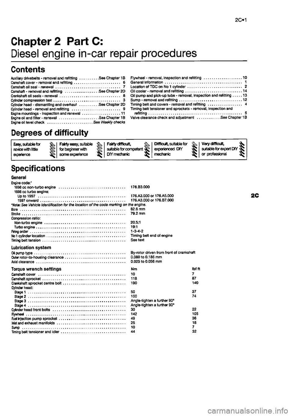
Chapter 2 PartC:
Diesel engine in-car repair procedures
Contents
Auxiliary drivebelts - removal and refitting See Chapter 1B Camshaft cover - removal and refitting 6 Camshaft oil seal - renewal 7 Camshaft - removal and refitting See Chapter 20 Crankshaft oil seats - renewal 8 Cylinder compression test « 3 Cylinder head - dismantling and overhaul See Chapter 20 Cylinder head - removal and refitting 9 Engine mountings - inspection and renewal 11 Engine oil and fitter - renewal See Chapter 18 Engine oil level check See Weekly checks
Degrees of difficulty
Flywheel * removal, inspection and refitting 10 General information 1 Location of TDC on No 1 cylinder 2 Oil cooler - removal and refitting 14 Oil pump and pick-up tube • removal, Inspection and refitting 13 Sump • removal and refitting 12 Timing belt and covers • removal and refitting 4 Timing belt tensioner and sprockets - removal, Inspection and refitting 5 Valve clearance check and adjustment See Chapter 1B
Easy,
suitable for novice
with Irttle
|| experience g^
FaMy
eesy,
suitable ^
forbeglnnerwilti
some experience ^
Falrtydfficult, ^ suitable
for
competent DIYmechanic ^
Difficult, suitable
for & experienced DIY mechanic ^
Very
difficult,
^ suitable
for
expert
DfY
jR or professional ^
Specifications
General Engine code:' 1698 cc non-turbo engine 176.B3.000 1698 cc turbo engine: Up to 1997 t76.A3.00aor176.A5.000 1997 onward 176.A3.000or176.B7.000 •Note: See Vehicle Identification for the location of the code marking on the engine. Bore 82.6 mm Stroke 79.2 mm Compression ratio: Non-turbo engine 20.5:1 Turbo engine 19:1 Firing order 1-3-4-2
No 1
cylinder location Timing belt end of engine Titling belt tension See text
Lubrication system Oi pump type By-rotor driven from front of crankshaft Outer rotor-to-houslng clearance 0.080 to 0.186 mm Axial clearance 0.025 to 0.056 mm
Torque wrench settings Nm ibf ft Camshaft cover 10 7 Camshaft sprocket 11B 87 Crankshaft sprocket centre bolt 190 140 Cylinder head: Stage 1 50 37 Stage 2 100 74 StageS Angle-tighten a furtfier 90" Stage 4 Angle-tighten a further 90° CySnder head front bolts 30 22 Flywheel 142 105
Fuel
injection pump sprocket 49 36 Inlet and exhaust manifolds 25 18 Sump 10 7 Timing belt tensioner and idler 44 32
Page 76 of 225
2C*2 Diesel engine in-car repair procedures
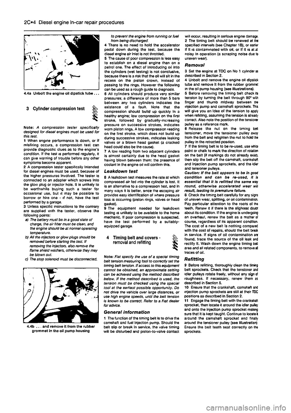
4.4a Unbolt the engine oil dipstick tube...
3 Cylinder compression test
Note: A compression tester specifically designed for diesef engines must be used for this test. 1 When engine performance Is down, or if misfiring occurs, a compression test can provide diagnostic clues as to the engine's condition, If the lest is performed regularly, it can give warning of trouble before any other symptoms become apparent. 2 A compression tester specifically Intended for diesel engines must be used, because of the higher pressures involved. The Ie6ter is connected to an adapler which screws Into the glow plug or injector hole. It is unlikely to be worthwhile buying such a tester for occasional use. but it may be possible to borrow or hire one • if not. have the test performed by a garage. 3 Unless specific instructions to the contrary are supplied with the tester, observe the following points: 9) The battery must bo in a good state of charge, the air titter must be clean, end the engine should be at normal operating temperature. b) AH the in/actors or glow plugs should be removed before starting the lest. If removing the injectors, also remove the flame shield washers, otherwise they may be blown out. c) The stop solenoid must be disconnected.
4.4b ... and remove it from the rubber grommet in the oil pump housing
fo prevent the engine from running or fuel from being discharged. 4 There is no need to hold the accelerator pedal down during the test, because the diesel engine air inlet is not throttled. 5 The cause of poor compression Is less easy to establish on a diesel engine than on a petrol one. The effect of introducing oil into the cylinders (wet testing) Is not conclusive, because there is a risk that the oil will sit in the recess on the piston crown, instead of passing to the rings. However the following can be used as a rough guide to diagnosis. 6 All cylinders should produce very similar pressures; a difference of more than 5 bars between any two cylinders Indicates the existence of a fault. Note that the compression should build up quickly In a healthy engine; low compression on the first stroke, followed by gradually-increasing pressure on successive strokes, indicates worn piston rings. A low compression reading on the first stroke, which does not build up during successive strokes, indicates leaking valves or a blown head gasket (a cracked hoad could also be the cause). 7 A low reading from two adjacent cylinders Is almost certainly due to the head gasket having blown between them: the presence of coolant In the engine oil will confirm this,
Leakdown test 8 A leakdown test measures the rate at which compressed air fed into the cylinder Is lost. It is an alternative to a compression test, and in many ways it is better, since the escaping air provides easy identification of where pressure loss is occurring (piston rings, valves or head gasket). 9 The equipment needed for leakdown testing is unlikely to be available to the home mechanic. If poor compression Is suspected, have the test performed by a suitably-equipped garage.
4 Timing belt and covers -removal
and
refitting
Note: Fiat specify the use of a spec/a/ timing belt tension measuring tool to correctly set the timing belt tension. If access to this equipment cannot be obtained, an approximate setting can be achieved using the method described below. If the method described is used, the tension must be checked using the special tool at the earliest possible opportunity. Do not drive the vehicle over large distances, or use high engine speeds, until the belt fens/on rs known to be correct. Refer to a Fiat dealer for advice.
General Information 1 The function of the timing belt is to drive the camshaft and fuel injection pump. Should the belt slip or break in service, the valve timing will be disturbed and piston-to-valve contact
will occur, resulting In serious engine damage. 2 The timing bolt should be renewed at the specified intervals (see Chapter 1B), or earlier If It is contaminated with oil. or If It is at al noisy In operation (a scraping noise due to uneven wear),
Removal 3 Set the engine at TDC on No 1 cylinder
as
described in Section 2. 4 Unbolt and remove tho engine oil dipstick tube and remove It from the rubber gromme! in the oil pump housing (see illustrations), 5 Before removing the timing belt check rts tension by turning the belt through 90" with finger and thumb midway between u* injection pump and camshaft sprockets. This will give you an Idea of the tension to apply when refitting, assuming the tension is already correct. Also note the position of the tensions pulley as a reference mark. 6 Release tho nut on the timing bea tensioner, move the tensioner pulley away from the belt and retlghten the nut to hold the pulley in the retracted position. 7 If the timing belt is to be re-used, use white paint or chalk to mark the direction of rotation on the belt (if markings do not already exist), then slip the belt off the camshaft, crankshaft and injection pump sprockets, and the idler and tensioner pulleys. Caution: If the belt appears to be In good condition and can be re-used, it fs essential that It Is refitted the same
wsy
round, otherwise accelerated wear will result, leading fo premature failure. 8 Check the timing belt carefully for any signs of uneven wear, splitting, or oil contamination. Pay particular attention to the roots of the teeth. Renew it if there is the slightest doutt about its condition. If the engine is undergoing an overhaul, renew the belt as a matter of course, regardless of its apparent conditio*. The cost of a new belt Is nothing compa/ed with the cost of repairs, should the belt freak in service. If signs of oil contamination art found, trace the source of the oil leak and rectify It. Wash down the engine timing baft area and all related components, to remove
sd
traces of oil.
Refitting 9 Before refitting, thoroughly clean the tknmg belt sprockets. Check that the tensioner and idler pulleys rotate freely, without any sign ol roughness. If necessary, renew them as described in Section 5. 10 Ensure that the crankshaft, camshaft and injection pump sprockets are still at their TDC positions as described In Section 2. 11 Engage the timing belt with the crankshaft sprocket, then locate it around the idler pufiey and onto the Injection pump sprocket making sure that it is kept taught. Continue to locate! around the camshaft sprocket and finally around Ihe tensioner pulley (see Illustration) Ensure the belt teeth seat correctly on Ihe sprockets.
Page 106 of 225
Apply a smear of clean engine oil to the gudgeon pin. Slide it Into the piston and through the connecting rod small-end. Check that the piston pivots freely on the rod. then secure the gudgeon pin in position with two new circlips. Ensure that each circlip is correctly located In Its groove in the piston.
Refitting and big-end bearing running ciearance check 27 Prior to refitting the piston/connecting rod assemblies, it Is recommended that the big-end bearing running clearance is checked as follows. Big-end bearing running clearance check 28 Clean the backs of the bearing shells, and the bearing locations in both the connecting rod and bearing cap. 29 Press the bearing shells into their locations, ensuring that the tab on each shell engages in the notch In the connecting rod and cap. Take care not to touch any shell's bearing surface with your fingers. If the onginal bearing shells are being used for the check, ensure that they are refitted in their original locations. The clearance can be checked in either of two ways. 30 One method is to refit the big-end bearing cap to Ihe connecting rod, ensuring that they are litted the correct way around, with the bearing shells in place. Wilh the cap retaining bolls correctly tightened, use an internal micrometer or vernier caliper to measure the internal diameter of each assembled pair of bearing shells. If the diameter of each corresponding crankshaft journal is measured and Ihen subtracted from the bearing internal diameter, the result will be the big-end beanng running clearance. 31 The second, and more accurate method is to use a product called Plasligauge. Ensure that the bearing shells are correctly fitted then place a strand of Plastlgauge on each (cleaned) crankpin journal. 32 Refit the (clean) piston/connecting rod assemblies to the crankshaft, and refit the bg-end bearing caps, using the marks made or noted on removal to ensure that they are fitted the correct way around. 33 Tighten the beanng cap bolts taking care not to disturb the Plastlgauge or rotate the connecting rod dunng the tightening sequence. 34 Dismantle the assemblies without rotating the connecting rods. Use the scale pnnted on the Plastigauge envelope to obtain the big-end bearing running clearance. 35 If the clearance is significantly different from that expected, the bearing shells may be Ihe wrong size (or excessively worn. If the original shells are being re-used). Make sure mat no dirt or oil was trapped between Ihe bearing shells and the caps or block when the clearance was measured. If the Plastigauge was wider al one end than at the other, the crankshaft journal may be tapered.
2D*10 Engine removal and overhaul procedures
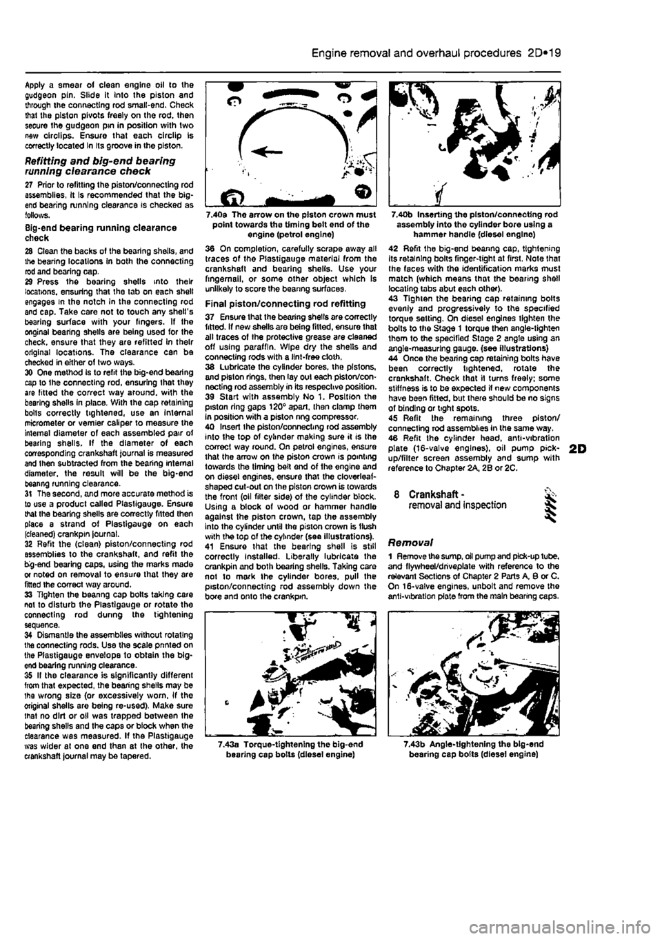
7.40a The arrow on the piston crown must point towards the timing belt end of the engine (petrol engine) 36 On completion, carefully scrape away all traces of the Plastigauge material from the crankshaft and bearing shells. Use your fingernail, or some other object which is unlikely to score the beanng surfaces.
Final piston/connecting rod refitting 37 Ensure that the bearing shells are correctly fitted. If new shells are being fitted, ensure that alt traces of the protective grease are cleaned off using paraffin. Wipe dry the shells and connecting rods with a lint-free cloth. 38 Lubricate the cylinder bores, the pistons, and piston rings, then lay out each piston/con-necting rod assembly in its respective position. 39 Start with assembly No 1. Position the piston ring gaps 120° apart, then clamp them in position with a piston nng compressor. 40 Insert Ihe piston/connecting rod assembly into the top of cylinder making sure it is Ihe correct way round. On petrol engines, ensure that the arrow on the piston crown is pointing towards the timing belt end of the engine and on diesel engines, ensure that the cloverleaf-shaped cut-out on the piston crown is towards the front (oil filter side) of the cylinder block. Using a block of wood or hammer handle against the piston crown, tap the assembly into the cylinder until the piston crown is Hush with the top of the cylinder (sea illustrations). 41 Ensure that the bearing shell is still correctly Installed. Liberally lubricate the crankpin and both bearing shells. Taking care not to mark the cylinder bores, pull the piston/connecting rod assembly down the bore and onto the crankpin.
7.40b Inserting the piston/connecting rod assembly into the cylinder bore using a hammer handle (diesel englno) 42 Refit the big-end beanng cap, tightening Its retaining bolts finger-tight at first, Note that Ihe faces with the identification marks must match (which means that the bearing shell locating tabs abut each other). 43 Tighten the bearing cap retaining bolts evenly and progressively to the specified torque setting. On diesel engines tighten the bolts to the Stage 1 torque then angle-tighten them to the specified Stage 2 angle using an angle-measuring gauge, (see illustrations) 44 Once the bearing cap retaining bolts have been correctly tightened, rotate the crankshaft. Check that il turns freely; some stiffness is to be expected if new components have been fitted, but there should be no signs of binding or tight spots. 45 Refit the remaining three piston/ connecting rod assemblies in the same way. 46 Refit the cylinder head, anti-vibration plate (16-valve engines), oil pump pick-up/filter screen assembly and sump with reference to Chapter 2A, 2B or 2C.
8 Crankshaft -removal and inspection 35
Removal 1 Remove the
sump,
oil pump and pick-up tube, and flywheel/driveplate with reference to the relevant Sections of Chapter 2 Parts A, 8 or C. On 16-valve engines, unbolt and remove the anti-vibration plate from the main bearing caps.
7.43a Torque-tightening the big-end bearing cap bolls (diesel engine) 7.43b Angle-tightening the big-end bearing cap bolts (diesel engine)