Torque settings FIAT PUNTO 1998 176 / 1.G Workshop Manual
[x] Cancel search | Manufacturer: FIAT, Model Year: 1998, Model line: PUNTO, Model: FIAT PUNTO 1998 176 / 1.GPages: 225, PDF Size: 18.54 MB
Page 21 of 225
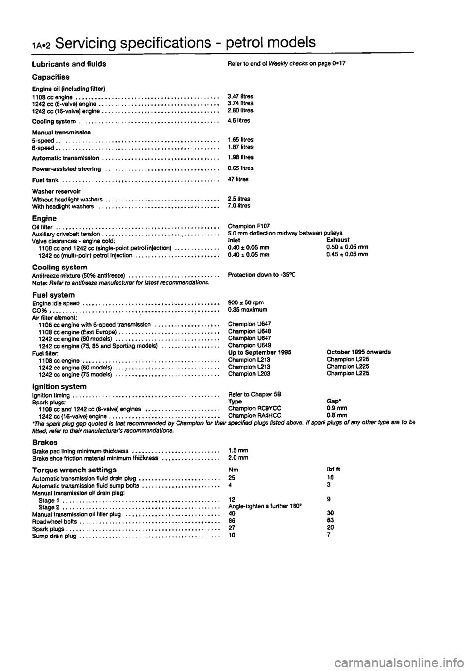
ia.2 Servicing specifications - petrol models
Lubricants and fluids Refer to end ot Weekly checks on page 0*17
Capacities Engine oil (including filter) 1108 cc engine 3.47 litres 1242 cc (8-valvB) engine 3.74 litres 1242 cc (16-valve) engine 2.80 litres Cooling system 4,6 litres
Manual transmission 5-spee d 1.65 litres 6-spee d 1.87 litres Automatic transmission 1.98 litres Power-assisted steering 0.65 Irtres Fuel tank 47 litres Washer reservoir Wllhouthesdllghl washers 2.5 litres With headlight washers 7.0 litres
Engine Olf niter - Champion F107 Auxiliary drivebelt tension 5.0 mm deflection midway between pulleys Valve clearances - engine cold: Inlet Exhaust 1108 cc and 1242 cc (single-point petrol injection) 0.40±0.05mm 0.50±0.05mm 1242 cc (multi-point petrol Injection 0.40 1 0.05 mm 0.45 1 0.05 mm
Cooling system Antifreeze mixture (50% antifreeze) Protection down to -35"C Note: Refer to antifreeze manufacturer for latest recommendations.
Fuel system Engine idle speed . 900 * 50 rpm CO 0.35 maximum Air filter element: 1108 cc engine with 6-speed transmission -... Champion U647 1108 cc engine (Easl Europe) Champion U648 1242 cc engine (60 models) Champion U647 1242
CO
engine (75.85 and Sporting models) Champion U649 Fuel filler: Up to September 1995 October 1995 onwards 1108 cc engine Champion L213 Champion L225 1242 cc engine (60 models) Champion L213 Champion 1225 1242 cc engine {75 models) Champion L203 Champion L225
Ignition system Ignition liming Refer to Chapter 58 Spark plugs: Type Gap* 1108 cc and 1242 cc (6-valve) engines Champion RC9YCC 0.9 mm 1242 cc (16-valve) engine ,... Champion RA4HCC 0.8 mm The spark plug gap quoted Is Diet recommenced by Champion for their specined plugs listed above. If spar* plugs of any other type ere to be fitted, refer to their manufacturer's recommendations. Brakes Brake pad lining minimum thickness 15 mm Brake shoe friction material minimum thickness 2.0 mm
Torque wrench settings Nm itrfft Automatic transmission lluld drain plug 25 10 Automatic transmission fluid sump bolts 4 3 Manual transmission oil drain plug: Stage 1 12 9 Stage 2 Angle-lighten a further 180" Manual transmission oil filler plug 40 30 Roadwheel bolts 86 83 Spark plugs 27 20 Sump drain plug 10 7
Page 38 of 225
1B.2
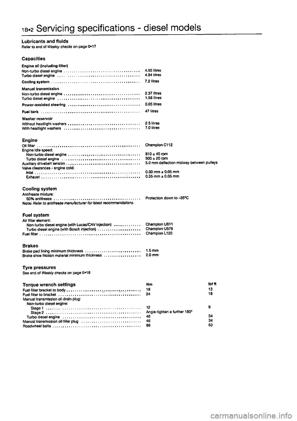
Servicing specifications - diesel models
Lubricants and fluids Refer to end of Weekly checks on page 0*17
Capacities Engine oil (including filter) Non-turbo diesei engine 4.95 litres Turbo diesel engine 4.84 litres Cooling system 7.2 litres
Manual transmission Non-turbo diesel engine 2.37 litres Turbo diesei engine t .98 litres Power-assisted steering 0.65 litres
Fuel tank 47 litres Washer reservoir Without headlight washers 2.5 litres With headlight washers 7.0 litres
Engine Oil fitter Engine Idle speed: Non-turbo diesel engine Turbo diesel engine Auxiliary drivebelt tension ...... Valve clearances • engine cold: Inlet Exhaust
Champion C112
8l0«40rpm 900 ± 20 rpm 5.0 mm deflection midway between pulleys
0.30 mm * 0.05 mm 0.35 mm ± 0.05 mm
Cooling system Antifreeze mixture: 50% antifreeze Protection down to-35°C Note: Refer to antifreeze manufactuivr for latest recommendations.
Fuel system Air filter element: Non-turbo diesel engine (with Lucas/CAV Injection) Champion U611 Turbo diesel engine (with Bosch Injection) Champion U579 Fuel filter Champion L120
Brakes Brake pad lining minimum thickness 1-5 mm Brake shoe friction material minimum thickness 2.0 mm
Tyre pressures See end of Weekly checks on page 0*18
Torque wrench settings Fuel filter bracket to body ..... « Fuel filter to bracket i........ Manual transmission oil drain plug: Non-turbo diesel engine: Stage 1 Stage 2 Turbo diesel engine Manual transmission oil filler plug Roadwheel bolts
Nm Ibfft 18 13 24 18
12 9 Angle-tighten a further 180® 46 34 46 34
Page 52 of 225
2A*10 SOHC (8-valve) petrol engine in-car repair procedures
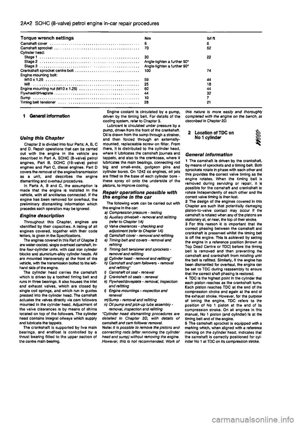
Torque wrench settings Nm
IM
ft Camshaft cover 8 6 Camshaft sprocket 70 52 Cylinder head; Stage 1 30 22 Stage 2 Angle-lighten a further 90° Siege 3 Angle-tighten a further 90B Crankshaft sprocket centre bott 100 74 Engine mounting bolt: M10X1.25 69 44 MB 25 18 Engine mounting nut (M10x 1.25) 60 44 Flywheet/driveplate 44 32 Sump 10 7 Timing belt tensJoner 28 21
1 General information
Using this Chapter Chapter 2 is divided Into four Parts: A. 8. C and D. Repair operations that can be carried out with the engine in the vehicle are described in Part A. SOHC (8-valve) petrol engines, Part B. DOHC (18-valve) petrol engines and Part C, diesel engines. Part 0 covers the removal of the engine/transmission as a unit, and describes the engine dismantling and overhaul procedures. In Parts A, 9 and C, the assumption Is made lhat the engine is Installed in the vehicle, with sll ancillaries connected. If the engine has been removed for overhaul, the preliminary dismantling Information which precedes each operation may be ignored.
Engine description Throughout this Chapter, engines are identified by their capacities. A listing of all engines covered, together with their code letters, is given in the Specifications. The engines covered In this Part of Chapter 2 are water-cooled, single overhead camshaft, in-line four-cylinder units, with cast Iron cylinder Mocks and aluminium-alloy cylinder heads. All are mounted transversely at the front ot the vehicle, with the transmission bolted to the left-hand side of the engine, The cylinder head carries the camshaft which is driven by a toothed timing belt and runs In three bearings. It also houses the inlet and exhaust valves, which are closed by single coil springs, and which run in guides pressed Into the cylinder head. The camshaft actuates the vatves directly via cam followers mounted in the cylinder head. Adjustment of the valve clearances is by means of shims located on top of the followers. The cylinder head contains Integral oitways which supply and lubricate the tappets. The crankshafl Is supported by five main bearings, and endftoat is controlled by a thrust bearing fitted to the upper section of the centre main bearing.
Engine coolant is circulated by 8 pump, driven by the timing belt. For details of the cooling system, refer to Chapter 3. Lubricant is circulated under pressure by a pump, driven from ihe front of the crankshaft. Oil Is drawn from the sump through a strainer, and then forced through an externally-mounted, replaceable screw-on filter. From there, It is distributed to the cylinder head, where It lubricates the camshaft journals and tappets, and also to the crankcase, where il lubricates the main bearings, connecting rod big and smell-ends, gudgeon pins and cylinder bores. On 1242 cc engines, oil jets are fitted lo the base of each cylinder bore -these spray oil onto the underside of the pistons, to Improve cooling.
Repair operations possible with the engine in the car The following work can be carried out with the engine in the car a) Compression pressure - testing b) Auxiliary drivebelt - removal and refitting (refer to Chapter 1A) c) Vatve clearances - checking and adjustment (refer to Chapter I A) d) Camshaft cover - removal and refitting e) Timing belt and covens - removal and refitting f) Timing belt tensioner and sprockets -removal and refitting g) Cylinder head - removal and refitting' h) Camshaft and cam followers • removal and refitting' t) Camshaft oil seal - renews/ j) Crankshaft oil seals - renewal k) Flywheel/dnvepfate • removal, inspection and refitting l) Engine mountings - inspection and renewal m)Sump - removal and refitting n) Oil pump and pick-up tube assembly
•
removai. inspection and refitting *Cylinder head dismantling procedures are detailed In Chapter SO, with details of camshaft and cam follower removal. Note: It is possible to remove the pistons and connecting rods (after removing the cylinder head and sump) without removing the engine. However, this is not recommended. Work of
this nature is more easily and thoroughly completed with the engine on the bench, as described In Chapter 2D.
2 Location of
TDC
on % No
1
cylinder
General Information 1 The camshaft Is driven by the crankshaft, by means of sprockets and a timing belt. Both sprockets rotate In phase with each other and this provides the correct valve timing as the engine rotates. When (he liming belt is removed during servioing or repair, it Is possible for the camshaft and crankshaft to rotate Independently of each other and the correct valve timing Is then lost. 2 The design of the engines covered In this Chapter are such lhat potentially damaging piston-to-valve contact may occur if the camshaft is rotated when any of the pistons are stationary at, or near, the top of their stroke. 3 For this reason it is important lhat Ihe correct phasing between the camshaft and crankshaft is preserved whilst the timing belt Is off the engine. This is achieved by setting the engine In a reference position (known as Top Dead Centre or TDC) before the timing belt Is removed and then preventing the camshaft and crankshaft from rotating until the belt is refitted. Similarly, if ths engine has been dismantled for overhaul, the engine can be set to TOC during reassembly to ensure that Ihe correct shaft phasing is restored. 4 TDC is the highest point In the cylinder that each piston reaches as the crankshaft turns. Each piston reaches TDC at Ihe end of the compression stroke and again at the end of the exhaust stroke. However, for the purpose of timing the ongine. TDC refers to the position of No 1 piston at the end of Its compression stroke. On ail engines In this manual, No 1 piston (and cylinder) Is at the timing belt end of the engine. 5 The camshaft sprocket Is equipped with a marking which, when aligned with a reference marking on the cylinder head, indicates that the camshaft is correctly positioned for cyl-inder No 1 al TDC on its compression stroke.
Page 57 of 225
2A*10 SOHC (8-valve) petrol engine in-car repair procedures
Preparation for refitting 16 The mating faces of the cylinder head and cylinder block must be perfectly clean before
refitting
the head. Use a hard plastic or wooden scraper to remove all traces of gasket and carbon; also clean the piston crowns. Take padicular care when cleaning the piston crowns as the soft aluminium alloy is easily damaged. Make sure that the carbon is not afowed to enter the oil and water passages -Ihs is particularly important for the lubrication
system, as
carbon could block the oil supply to
Ihe
engine's components. Using adhesive tape
and
paper, seal the water, oil and bolt holes in tf« cylinder block. To prevent carbon entering twgap between the pistons and bores, smear
a
iittte grease in the gap. After cleaning each piston, use a small brush to remove all traces of grease and carbon from the gap, then wipe away the remainder with a clean rag. Clean all
ttie pistons
in the same way. 17 Check the mating surfaces of the cylinder block and the cylinder head for nicks, deep scratches and other damage. If slight, they may be removed carefully with a file, but if (xcassive, machining may be the only alternative to renewal. If warpage of the Cytodar head gasket surface is suspected, use a straight-edge to check it for distortion.
Refer
to Part 0 of this Chapter if necessary. 18 Check the condition of the cylinder head
MRS.
and particularly their threads, whenever
they are
removed. Wash the bolts In a suitable solvent, and wipe them dry. Check each bolt for any sign of visible wear or damage, renewing them if necessary.
Refitting 18 Before refitting Ihe assembled cylinder head, make sure that the head and block mating surfaces are perfectly clean, and that
the
bolt holes in the cylinder block have been
mopped
out to clear any oil. 20 Check that the camshaft and crankshaft sprocket timing marks are still aligned with tteir respective cylinder head and oil pump covtr marks as described in Section 2. 21 The new gasket should not be removed from its nylon cover until required for use. Fit
the
gasket dry, and make sure that the mating surfaces on the head and block are perfectly dean.
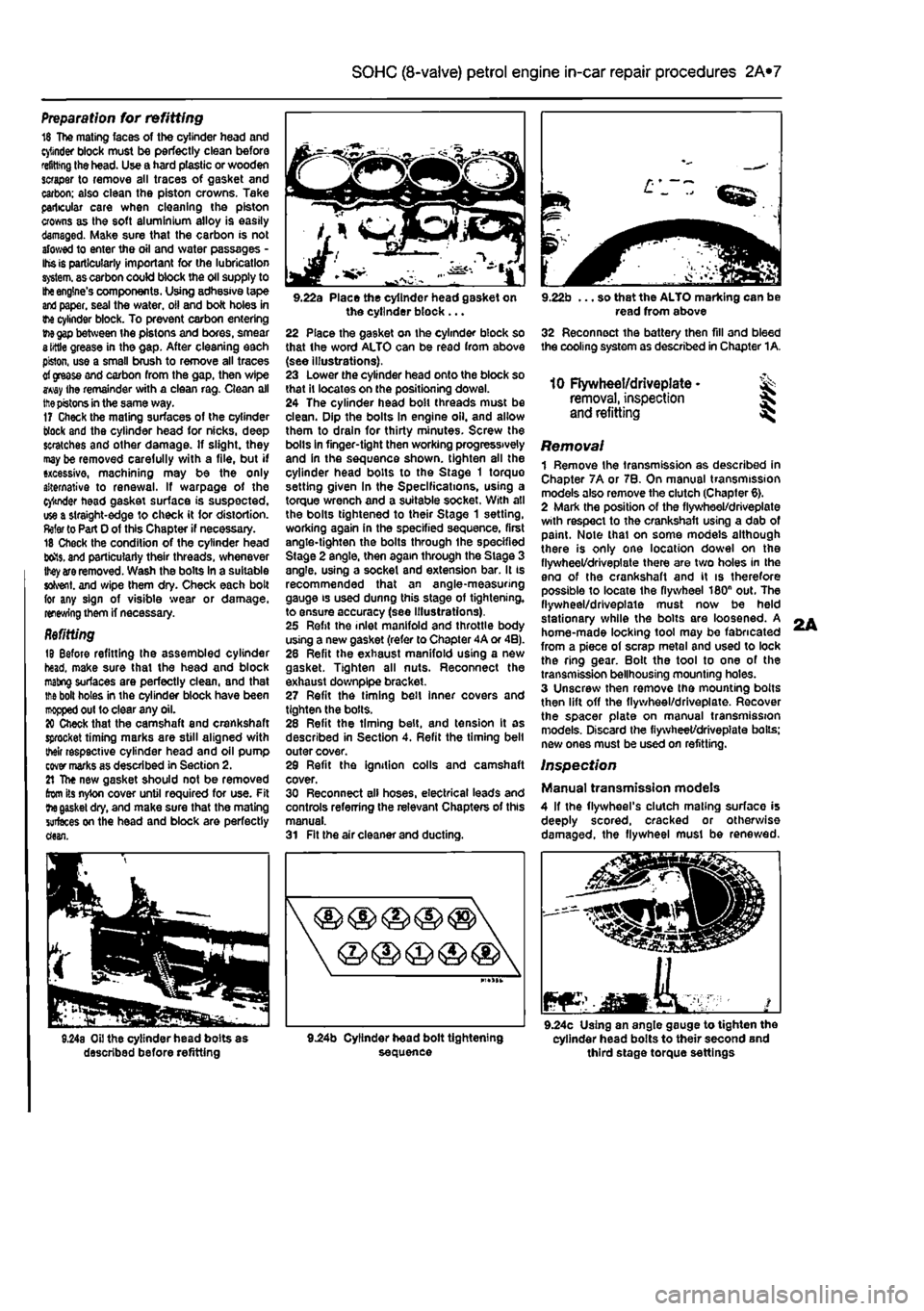
9.22a Place the cylinder head gasket on the cylinder block ... 22 Place the gasket on the cylinder block so that the word ALTO can be read from above (see illustrations). 23 Lower the cylinder head onto the block so that It locates on the positioning dowel. 24 The cylinder head bolt threads must be clean. Dip the bolts In engine oil. and allow them to drain for thirty minutes. Screw the bolls in finger-tight then working progressively and in the sequence shown, tighten all the cylinder head bolts to the Stage 1 torque setting given In the Specifications, using a torque wrench and a suitable socket. With all the bolts tightened to their Stage 1 setting, working again in the specified sequence, first angle-tighten the bolts through ihe specified Stage 2 angle, then again through the Stage 3 angle, using a socket and extension bar. It is recommended that an angle-measuring gauge is used dunng this stage of tightening, to ensure accuracy (see Illustrations). 25 Refit the inlet manifold and throttle body using a new gasket (refer to Chapter 4A or 4B). 28 Refit the exhaust manifold using a new gasket. Tighten all nuts. Reconnect the exhaust downplpe bracket. 27 Refit the timing belt inner covers and tighten the bolls. 28 Refit the timing belt, and tension It as described in Section 4. Refit the timing belt outer cover. 29 Refit the ignition colls and camshaft cover. 30 Reconnect all hoses, electrical leads and controls referring the relevant Chapters of this manual. 31 Fit the air cleaner and ducting.
9.22b ... so that the ALTO marking can be read from above 32 Reconnect the battery then fill and bleed the cooling system as described in Chapter 1A.
10 Flywheel/driveplate • ^ removal, inspection
and
refitting ^
Removal 1 Remove the transmission as described in Chapter 7A or 7B. On manual transmission models also remove the clutch (Chapter 6). 2 Mark the position of the flywheel/driveplate with respect to the crankshaft using a dab of paint. Note thai on some models although there is only one location dowel on the flywheel/driveplate there are two holes in the eno of the crankshaft and it is therefore possible to locate Ihe flywheel 180n out. The flywheel/driveplate must now be held stationary while the bolts are loosened. A home-made locking tool may be fabricated from a piece of scrap metal and used to lock the ring gear. Bolt the tool to one of the transmission bellhousing mounting holes. 3 Unscrew then remove the mounting bolts then lift off the flywheel/driveplate. Recover the spacer plate on manual transmission models. Discard the fiywheet/drivepiate boils; new ones must be used on refitting.
Inspection
Manual transmission models 4 If the flywheel's clutch mating surface is deeply scored, cracked or otherwise damaged, the flywheel must be renewed.
JEaMKA. mar 9.24c Using an angle gauge to tighten the cylinder head bolts to their second and third stage torque settings
L
Page 62 of 225
2A*10 SOHC (8-valve) petrol engine in-car repair procedures
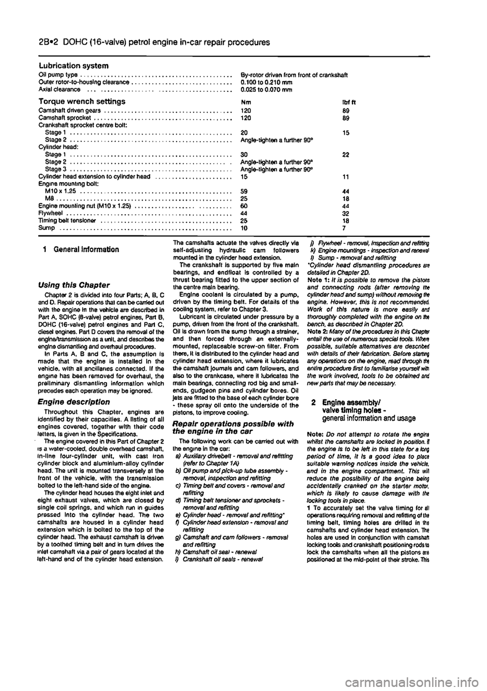
Lubrication system Oil pump type By-rotor driven from front of crankshaft Outer rotor-io-houslng clearance 0.100 to 0.210 mm Axial clearance 0.025 to 0.070 mm
Torque wrench settings Nm itrf ft Camshaft driven gears 120 89 Camshaft sprocket 120 89 Crankshaft sprocket centre bolt: Stage
1
20 15 Stage 2 Angle-tighten a further 90® Cylinder head: Stage
1
30 22 Stage 2 Angle-tighten a further 90" Stage 3 Angle-tighten a further 90° Cylinder head extension to cylinder head 15 11 Engine mounting bolt: M10
x
1.25 59 44 M8 25 18 Engine mounting nut (MlOx 1.25) 60 44 Flywheel 44 32 Timing belt tensioner 25 18 Sump 10 7
1 General information
Using this Chapter Chapter 2 is divided into four Parts; A, B. C and O. Repair operations that can be carried out with the engine hi the vehicle are described in Part A. SOHC (8-valve) petrol engines. Part B, DOHC (16-valve) petrol engines and Pari C, dlesei engines. Part D covers the removal of the engine/transmission as a unit, and describes the engine dismantling and overhaul procedures. In Parts A, B and C, the assumption Is made that the engine is Installed In the vehicle, with all ancillaries connected. If the engine has been removed for overhaul, the preliminary dismantling information which precedes each operation may be ignored.
Engine description Throughout this Chapter, engines are identified by their capacities. A listing of all engines covered, together with their code letters, Is given in the Specifications. The engine covered in this Part of Chapter 2 is a water-cooled, double overhead camshaft, in-line four-cylinder unit, with cast iron cylinder block and aluminium-alloy cylinder head. The unit is mounted transversely at the front of the vehicle, with the transmission bolted to the left-hand side of the engine. The cylinder head houses the eight inlet and eight exhaust valves, which are closed by single coil springs, and which run in guides pressed Into the cylinder head. The two camshafts are housed in 8 cylinder head extension which is bolted to the top of the cylinder head. The exhaust camshaft is driven by a toothed timing belt and In turn drives the inlet camshaft via a pair of gears located at the left-hand end of the cylinder head extension.
The camshafts actuate the valves directly via self-adjusting hydraulic cam followers mounted in the cylinder head extension. The crankshaft is supported by five main bearings, and endfioat is controlled by a thrust bearing fitted to (he upper section of the centre main bearing. Engine coolanl is circulated by a pump, driven by the timing belt. For details of the cooling system, refer to Chapter 3. Lubricant is circulated under pressure by a pump, driven from the front of the crankshaft. Oil is drawn from Ihe sump through a strainer, and then forced through an externally-mounted, replaceable screw-on filter. From there, It is distributed to the cylinder head and cylinder head extension, where it lubricates the camshaft journals and cam followers, and also to the crankcase, where it lubricates the main bearings, connecting rod big and small-ends. gudgeon pins and cylinder bores. Oil Jets are fitted to the base of each cylinder bore - these spray oil onto the underside of the pistons, to improve cooling.
Repair operations possible with the engine in the car The following work can be carried out with the engine in the car: a) Auxiliary drivebett - removal and refitting (refer to Chapter 1A) b) Oil pump and pick-up tube assembly -removal, Inspection and refitting c) Timing belt and covers • removal and refitting d) Timing belt tensioner and sprockets -removal and refitting e) Cylinder head - removal and refitting' f) Cylinder hoad extension - removal and refitting g) Camshaft and cam followers - removal and refitting h) Camshaft oil seal - renewal i) Crankshaft oil seals • renewal
f) Flywheel - removal, inspection and
refitting
k) Engine mountings - Inspection and
renews'
f) Sump • removal and refitting 'Cylinder head dismantling procedures are detailed In Chapter 2D. Note 1: It is possible to remove the
pistons
and connecting rods (after removing (to cylinder head and sump) without removing
tt*»
engine. However, this Is not recommended. Work of this nature is more easily and thoroughly completed with the engine on fix bench, as described in Chapter 20. Note
2x
Many of the procedures in this Ctopfer entail the use of numerous special tools. Whet possible, suitable alternatives are descnbei with details of their fabrication. Before starring any operations on the engine, read through
tto
entire procedure first to familiarise yourself
wft
the work involved, tools to be obtained mi new parts that may be necessary.
2 Engine assembly/ valve timing holes -genera! information
and
usage
Note: Do not attempt to rotate the angint whilst the camshafts are locked In position,
il
the engine is to be left in this state foratofi$ period of time. It Is a good idea to plect suitable warning notices inside the vehicle, and in the engine compartment. This wfl reduce the possibility of the engine being accidentally cranked on the starter motor, which is likely to cause damage with the locking tools In place. 1 To accurately set the valve timing for ell operations requiring removal and refitting of
the
timing belt, liming holes are drilled in ihe camshafts and cylinder head extension. Ihe holes are used In conjunction with camshaft locking tools and crankshaft positioning
rods w
lock the camshafts when all the pistons me positioned at the mid-point of their stroke. Ths
Page 73 of 225
2C«1
Chapter 2 PartC:
Diesel engine in-car repair procedures
Contents
Auxiliary drivebelts - removal and refitting See Chapter 1B Camshaft cover - removal and refitting 6 Camshaft oil seal - renewal 7 Camshaft - removal and refitting See Chapter 20 Crankshaft oil seats - renewal 8 Cylinder compression test « 3 Cylinder head - dismantling and overhaul See Chapter 20 Cylinder head - removal and refitting 9 Engine mountings - inspection and renewal 11 Engine oil and fitter - renewal See Chapter 18 Engine oil level check See Weekly checks
Degrees of difficulty
Flywheel * removal, inspection and refitting 10 General information 1 Location of TDC on No 1 cylinder 2 Oil cooler - removal and refitting 14 Oil pump and pick-up tube • removal, Inspection and refitting 13 Sump • removal and refitting 12 Timing belt and covers • removal and refitting 4 Timing belt tensioner and sprockets - removal, Inspection and refitting 5 Valve clearance check and adjustment See Chapter 1B
Easy,
suitable for novice
with Irttle
|| experience g^
FaMy
eesy,
suitable ^
forbeglnnerwilti
some experience ^
Falrtydfficult, ^ suitable
for
competent DIYmechanic ^
Difficult, suitable
for & experienced DIY mechanic ^
Very
difficult,
^ suitable
for
expert
DfY
jR or professional ^
Specifications
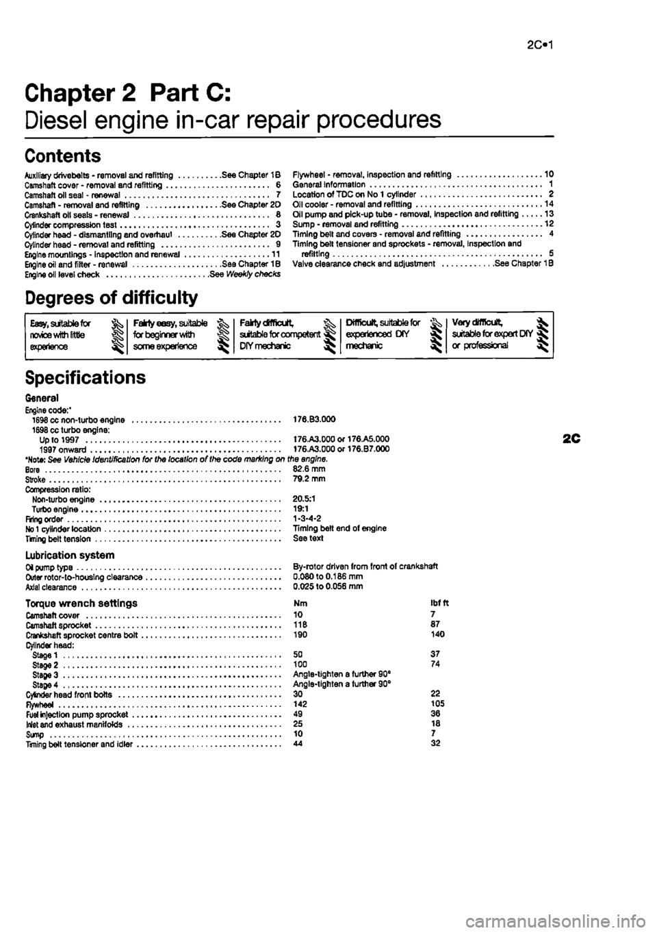
General Engine code:' 1698 cc non-turbo engine 176.B3.000 1698 cc turbo engine: Up to 1997 t76.A3.00aor176.A5.000 1997 onward 176.A3.000or176.B7.000 •Note: See Vehicle Identification for the location of the code marking on the engine. Bore 82.6 mm Stroke 79.2 mm Compression ratio: Non-turbo engine 20.5:1 Turbo engine 19:1 Firing order 1-3-4-2
No 1
cylinder location Timing belt end of engine Titling belt tension See text
Lubrication system Oi pump type By-rotor driven from front of crankshaft Outer rotor-to-houslng clearance 0.080 to 0.186 mm Axial clearance 0.025 to 0.056 mm
Torque wrench settings Nm ibf ft Camshaft cover 10 7 Camshaft sprocket 11B 87 Crankshaft sprocket centre bolt 190 140 Cylinder head: Stage 1 50 37 Stage 2 100 74 StageS Angle-tighten a furtfier 90" Stage 4 Angle-tighten a further 90° CySnder head front bolts 30 22 Flywheel 142 105
Fuel
injection pump sprocket 49 36 Inlet and exhaust manifolds 25 18 Sump 10 7 Timing belt tensioner and idler 44 32
Page 83 of 225
Diesel engine in-car repair procedures 2C*11
r
<3^
9.46a The locating dowel in the cylinder block 43 It is possible for the ptston crowns to stnke and damage the valve heads, if the camshaft is rotated v/ith the timing belt removed and the crankshaft set to TDC. For this reason, the crankshaft must be set to a position other than TDC on No t cylinder before the cylinder head is refitted. Use a socket on the crankshaft pulley centre bolt to turn the crankshaft in its normal direction of rotation, until all four pistons are positioned Halfway down their bores, v/ith No 1 piston on lis upstroke - approximately 90° before TDC.
Refitting 44 If the manifolds are being refitted before refitting the cylinder head proceed as follows, otherwise fit the manifolds later when the head is refitted. Ensure thai the inlet and exhaust manifold mating surfaces are completely clean, then locale the new gasket on the studs. 45 Locate the inlet and exhaust manifolds together with the turbocharger, where applicable, on the studs. Refit the nuts and washers and tighten to the specified torque.
sequence
f^/f
9.52b Tighten the cylinder head bolts to the Stage 1 and Stage 2 settings using a torque wrench
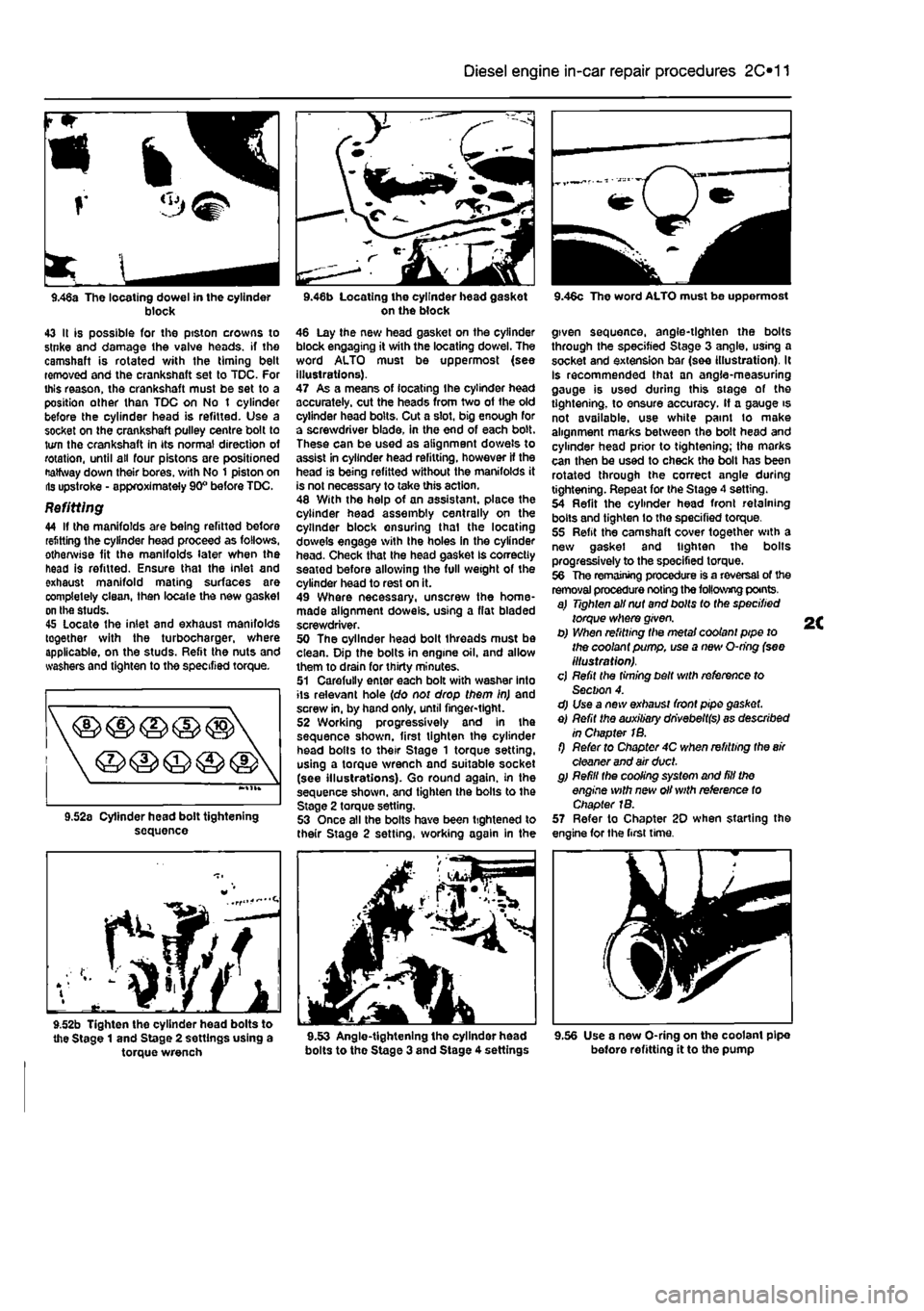
on the block 46 Lay the new head gasket on the cylinder block engaging it with the locating dowel. The word ALTO must be uppermost (see illustrations). 47 As a means of locating Ihe cylinder head accurately, cut the heads from two of the old cylinder head bolts. Cut a slot, big enough for a screwdriver blade, in the end of each bolt. These can be used as alignment dowels to assist in cylinder head refitting, however If the head is being refitted without the manifolds it is not necessary to take this action. 48 With the help of an assistant, place the cylinder head assembly centrally on the cylinder block ensuring thai the locating dowels engage with Ihe holes in the cylinder head. Check that the head gasket Is correctly seatod before allowing the full weight of the cylinder head to rest on it. 49 Where necessary, unscrew the home-made alignment dowels, using a flat bladed screwdriver. 50 The oyllnder head bolt threads must be clean. Dip the bolts in engine oil. and allow them to drain for thirty minutes. 51 Carefully enter each bolt with washer into its relevant hole (do not drop them in) and screw in, by hand only, until finger-tight. 52 Working progressively and In the sequence shown, first tighten the cylinder head bolts to their Stage 1 torque setting, using a torque wrench and suitable socket (see illustrations). Go round again, in the sequence shown, and tighten the bolls to the Stage 2 torque setting. 53 Once all the bolts have been tightened to their Stage 2 setting, working again in the
bolts to the Stage 3 and Stage 4 settings
9.46c The word ALTO must be uppermost
given sequence, angle-tighten the bolts through the specified Stage 3 angle, using a socket and extension bar (see illustration). It Is recommended that an angle-measuring gauge is used during this stage of the tightening, to ensure accuracy. If a gauge is not available, use white paint to make alignment marks between the bolt head and cylinder head prior to tightening; the marks can then be used to check tho bolt has been rotated through the correct angle during tightening. Repeat for the Stage 4 setting. 54 Refit the cylinder head front retaining bolts and tighten lo the specified torque. 55 Refit the camshaft cover together with a new gasket and tighten the bolts progressively to the specified torque. 56 The remaining procedure is a reversal of the removal procedure noting the following points. a) Tighten all nut and bolts to the specified torque where given. b) When refitting the metal coolant pipe to the coolant pump, use a new O-ring (see illustration). cj Refit the timing belt with reference to Section 4. d) Use a new exhaust front pipe gasket. e) Refit the auxiliary dhvebeltfs) as described in Chapter 1B. f) Refer to Chapter 4C when refitting the
air
cleaner and air duct. g) Refill the cooling system and fill the engine with new oil with reference to Chapter 1B. 57 Refer to Chapter 20 when starting the engine for the first time.
9.56 Use a new O-ring on the coolant pipe before refitting it to the pump
Page 90 of 225
2D*10 Engine removal and overhaul procedures
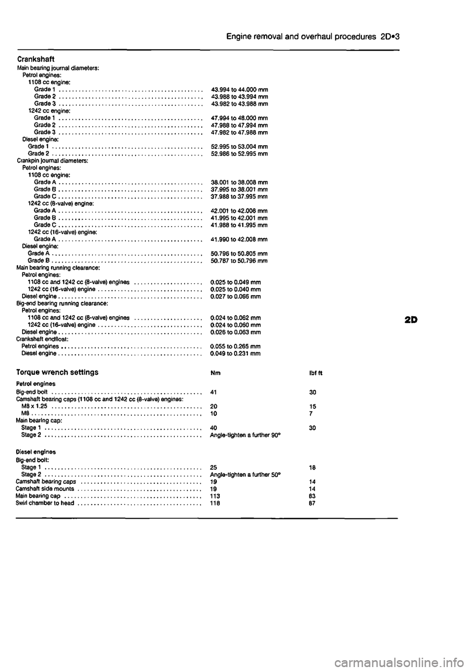
Crankshaft Main bearing journal diameters: Petrol engines: 1108 cc engine: Grade
1
43.994 to 44.000 mm Grade 2 43.988 to 43.994 mm Grade 3 43.982 to 43.988 mm 1242 cc engine: Grade
1
47.994 to 48.000 mm Grade 2 47.988 to 47.994 mm Grade 3 47.982 to 47.988 mm Diesel engine: Grade 1 52.995 to 53.004 mm Grade 2 52.986 to 52.995 mm Crankpin Journal diameters: Petrol engines: 1108 cc engine: Grade A 38.001 to 38.008 mm Grade 8 37.995 to 38.001 mm Grade C 37.988 to 37.995 mm 1242 cc (8-valve) engine: Grade A 42.001 to 42.008 mm Grade 8 41.995 to 42.001 mm Grade C 41.988 to 41.995 mm 1242 cc <16-valve) engine: Grade A 41.990 to 42.008 mm Diesel engine: Grade A 50.796 to 50.805 mm Grade B 50.787 to 50.796 mm Main bearing running clearance: Petrol engines: 1108 cc and 1242 cc (8-valve) engines 0.025 to 0.049 mm 1242 cc (16-valve) engine 0.025 to 0.040 mm Dlese! engine 0.027 to 0.066 mm Big-end bearing running clearance: Petrol engines: 1108 cc and 1242 cc (8-valve) engines 0.024 to 0.062 mm 1242 cc (16-vaJve) engine 0.024 to 0.060 mm Diesel engine 0.026 to 0.063 mm Crankshaft endtloat: Petrol engines 0.055 to 0.265 mm Diesel engine 0.049 to 0.231 mm
Torque wrench settings Nm ibf
t
Petrol engines Big-end bolt 41 30 Camshaft bearing caps (1108 cc and 1242 cc (8-valve) engines: M8x 1.25 20 15 MB 10 7 Main bearing cap: Stage 1 40 30 Stage 2 Angle-tighten a further 90°
Diesel engines Big-end bolt: Stage 1 25 18 Stage 2 Angle-tighten a further 50° Camshaft bearing caps 19 14 Camshaft side mounts 19 14 Main bearing cap 113 83 Swirl chamber to head 118 87
Page 113 of 225
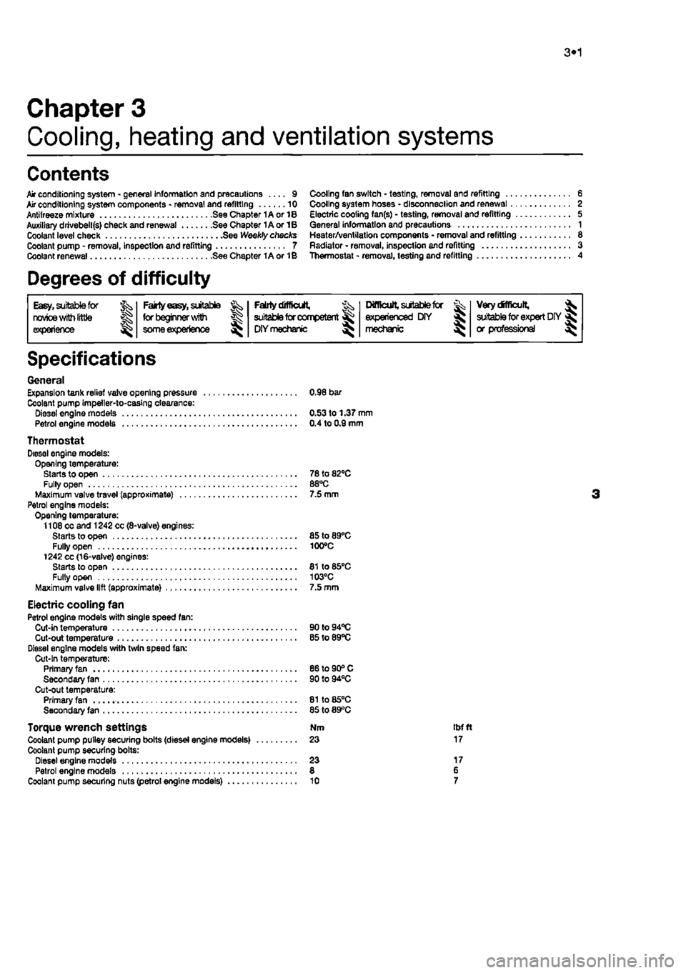
3*1
Chapter 3
Cooling, heating and ventilation systems
Contents
Air conditioning system - general Information and precautions .... 9 Mr conditioning system components * removal and refitting 10 Antifreeze mixture See Chapter 1A or 1B Auxiliary drivebell(s) check and renewal See Chapter 1A or IB Coolant level check See Weekly checks Coolant pump - removal, Inspection and refitting 7 Coolant renewal See Chapter 1A or 1B
Degrees of difficulty
Cooling fan switch - testing, removal and refitting 6 Cooling system hoses • disconnection and renewal 2 Electric cooling fan(s) - testing, removal and refitting 5 General information and precautions 1 Heater/ventilation components • removal and refitting 8 Radiator - removal, inspection and refitting 3 Thermostat - removal, testing and refitting 4
Easy,
suitable foe JS^, novice
with
little experience ^
Fairly
easy,
sutable for beginner witti
some experience
^
Faiilydifltctit,
suitable
for competent
DIY mechanic
^
Difficult,
sutable for & experienced DIY « mechanic ^
VerydMlcult, ^
suitable
for
expert DIY
« or professional
Specifications
General Expansion tank relief valve opening pressure 0.96 bar Coolant pump Impeller-to-casing clearance: Diesel engine models 0.53 to 1.37 mm Petrol engine models 0.4 to 0.9 mm
Thermostat Diesel engine models: Opening temperature: Starts to open 78 to 82*0 Fully open 88°C Maximum valve travel (approximate) 7.5 mm Petrol engine models: Opening temperature: 1108 cc and 1242 cc (8-valve) engines: Starts to open 85 to 89°C Fully open 100°C 1242 cc (16-valve) engines: Starts to open 81 to 85°C Fully open 103°C Maximum valve lift (approximate) 7.5 mm
Electric cooling fan Petrol engine models with single speed fan: Cut-in temperature 90to94°C Cut-out temperature B5 to 89°C Diesel engine models with twin speed fan: Cut-In temperature: Primary fan 86 to 90® C Secondary fan 90 to 94°C Cut-out temperature: Primary fan 81to85°C Secondary fan 85 to 89°C
Torque wrench settings Nm tbfft Coolant pump pulley securing bolts (diesel engine models) 23 17 Coolant pump securing bolts: Diesel engine models 23 17 Petrol engine models 8 6 Coolant pump securing nuts (petrol engine models) 10 7
Page 121 of 225
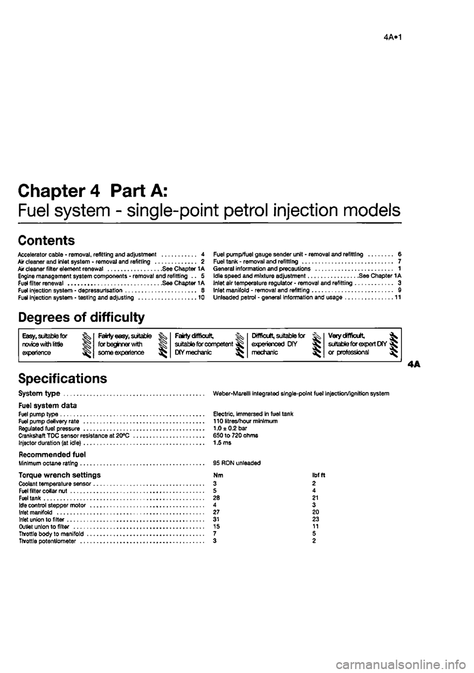
4A«1
Chapter 4 Part A:
Fuel system - single-point petrol injection models
Contents
Accelerator cable • removal, refitting and adjustment 4 Air cleaner and inlet system - removal and refitting 2 Air cleaner filter element renewal See Chapter 1A Engine management system components - removal 8nd refitting .. 5 fuel filter renewal See Chapter 1A Fuel injection system - depressurlsatlon 8 Fuel injection system • testing and adjusting 10
Degrees of difficulty
Fuel pump/fuel gauge sender unit - removal and refitting 8 Fuel tank - removal and refitting 7 General information and precautions 1 Idle speed and mixture adjustment See Chapter 1A Inlet air temperature regulator • removal and refitting 3 Inlet manifold - removal and refitting 9 Unleaded petrol - general Information and usage 11
Easy, suitable for Fairty easy, suitable Fairly difficult, Jx suitable for competent ^ OY mechanic ^
DifficUt, suitable tor % Very difficult, ^ novice with Me for begrmer with &
Fairly difficult, Jx suitable for competent ^ OY mechanic ^ experienced DIY > * suitable for expert D(Y JS or professional ^ experience some experience &
Fairly difficult, Jx suitable for competent ^ OY mechanic ^ mechanic > * suitable for expert D(Y JS or professional ^
Specifications
System type Weber-Marelll integrated single-point fuel injection/ignition system
Fuel system data Fuel pump type Electric, Immersed in fuel tank Fuel pump delivery rate 110 litres/hour minimum Regulated fuel pressure 1.0 ± 0.2 bar Crankshaft TDC sensor resistance at 20°C €50 to 720 ohms Injector duration (at idle)
1
£ ms
Recommended fuel Minimum octane rating 95 RON unleaded
Torque wrench settings Nm ibfft Coolant temperature sensor 3 2 Fuel filter collar nut S 4 Fuel tank 28 21 Idle control stepper motor 4 3 Inlet manifold 27 20 Inlet union to filter 31 23 Outlet union to filter 15 11 Throttle body to manifold 7 5 Throttle potentiometer 3 2