locks FIAT PUNTO 1998 176 / 1.G Workshop Manual
[x] Cancel search | Manufacturer: FIAT, Model Year: 1998, Model line: PUNTO, Model: FIAT PUNTO 1998 176 / 1.GPages: 225, PDF Size: 18.54 MB
Page 16 of 225
Weekly checks 015
Automatic transmission fluid level
Before you start: • Park the vohicle on level ground, and apply the handbrake firmly. Let the engine idle, and select P or N.
Safety First! • The need for frequent topping-up indicates a leak, which should bo Investigated immediately.
I
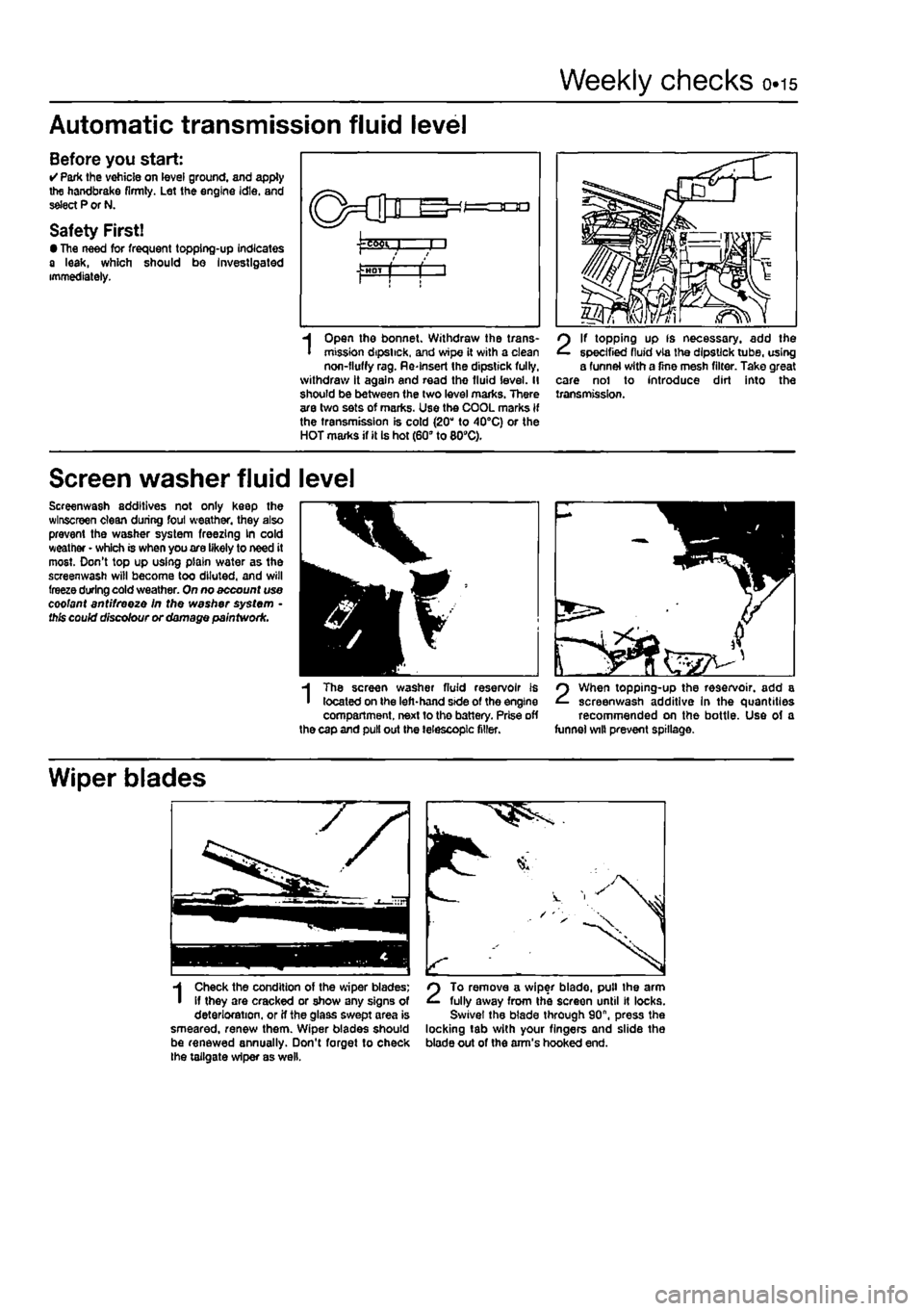
Open the bonnet. Withdraw the trans-mission dipstick, and wipe it with a clean non-fluffy rag. Re-Insert the dipstick fully, withdraw it again and read the fluid level. II should be between (he two level marks. There are two sets of marks. Use the COOL marks if the transmission is cold (20" to 40°C) or the HOT marks if it Is hot (60" to 809C).
2
If topping up fs necessary, add the specified fluid via the dipstick tube, using a funnel with a fine mesh filter. Take great care nol to introduce dirt into the transmission.
Screen washer fluid level
Screenwash additives not only keep the wlnscreen clean during foul weather, they also prevent the washer system freezing kn cold weather • which is when you are likely to need it most. Don't top up using plain water as the screenwash will become too diluted, and will freeze during cold weather. On no account use coolant antifreeze In the washer system • this could discolour or damage paintwork.
3H
m
I
The screen washer fluid reservoir is located on the left-hand side of the engine compartment, next to the battery. Prise off the cap and pull out the telescopic filler.
2
When topping-up the reservoir, add a screenwash additive In the quantities recommended on the bottle. Use of a funnel wilt prevent spillage.
Wiper blades
1
Check the condition of the wiper blades; if they are cracked or show any signs of deterioration, or if the glass swept area is smeared, renew them. Wiper blades should be renewed annually. Don't forget to check the tailgate wiper as well.
2
To remove a wiper blade, pull the arm fully away from the screen until It locks. Swivel the blade through 90", press the locking tab with your fingers and slide the blade out of the arm's hooked end.
Page 22 of 225
Maintenance schedule - petrol models 1A.3
The maintenance Intervals in this manual are provided with the assumption that you, not the dealer, will be carrying out the work. These axe the minimum maintenance intervals recommended by us for vehicles driven daily.
if you wish to keep your vehicle in peak condition at all times, you may wish to perform some of these procedures more often. We encourage frequent maintenance, because it enhances the efficiency.
performance and resale value of your vehicle. When the vehicle Is new, it should be serviced by a factory-authorised dealer service department, In order to preserve the factory warranty.
Every 250 miles (400 km) or weekly Q Refer to Weekly checks
Every 5000 miles (7500 km) or
6 months - whichever comes first • Renew the engine oil and filter (Section 3)
Note: Frequent oil and fitter changes am good tor the engine. We recommend changing the oil at the mileage specified here, or at least
twice
a year if the mileage covered Is a less.
Every 10 000 miles (15 000 km) or
12 months - whichever comes first
In
addition to the items listed above, cany out the following: Q Check the operation of the brake warning lamp (Section 4) • Check the front brake pads for wear (Section 5) • Check the underbody and sealant for damage (Section 6) • Hose and fluid leak check (Section 7) • Check the condition of the exhaust system and its mountings (Section 8) • Check the condition of the driveshaft gaiters (Section 9) • Renew pollen filter (Section 10) • Check exhaust gas content and idle speed (Section 11) • Check the steering and suspension components for condition and security (Section 12)
Every 20 000 miles (30 000 km) or
2 years - whichever comes first
In
addition to the Items listed above, carry out the following: • Check and if necessary adjust the tension of the auxiliary drlvebelt(s) (Section 13) • Check the freeplay and height of the clutch pedal (Section 14) • Check and if necessary adjust the valve clearances (Section 15) HI Check and if necessary tighten inlet and exhaust manifold mountings (Section 16) • Renew the fuel filter (Section 17) D Renew the air filter element (Section 18) O Renew the spark plugs (Section 19) • Check the condition of the HT cables (Section 20) • Check the engine management system (Section 21) Q Lubricate all hinges and locks (Section 22) O Check the headlight beam adjustment (Section 23) • Carry out a road test (Section 24)
Every 30 000 miles (45 000 km) or
3 years - whichever comes first In addition to the items listed above, cany out the following: • Check the operation of the Lambda sensor (Section 25) • Check and if necessary top-up the manual transmission oil level (Section 26) • Check the operation of the evaporative loss system (Section 27) • Automatic transmission inner filter and fluid renewal (Section 28)
Every 40 000 miles (60 000 km) or
4 years - whichever comes first In addition to the items fisted above, carry out the following: • Check the rear brake shoes for wear (Section 29) • Renew the timing belt (Section 30)"
*Noto: Although the normal interval for timing belt renewal is 70 000 miles (105 000 km), It is strongly recommended that the belt Is renewed at 40 000 miles (60 000 km) on vehicles which are subjected to Intensive use, ie. malniy short Journeys or a let of stop-start driving. The actual belt renewal Interval Is therefore very much up to the individual owner, but bear in mind that severe engine damage will result if the belt breaks.
Every 60 000 miles (90 000 km) or
6 years - whichever comes first in addition to the items listed above, cany out the following: • Check the condition and operation of the crankcase emission control system (Section 31)
Every 80 000 miles (120 000 km) • Renew the manual transmission oil (Section 32)
Every 2 years
(regardless of mileage) • Renew the engine coolant (Section 33) • Renew the brake fluid (Section 34)
Page 32 of 225
Every 20 000 miles - petrol models 1A.13
20 Ignition system check
81
21 Engine management system check
A
Warning: Voltages produced by an electronic ignition system are considerably higher than those produced by conventional ignition systems. Extreme care must be taken when working on the system with the Ignition switched on. Persons with surgically-Implanted cardiac pacemaker devices should keep well clear of the ignition circuits, components and test oquipment. 1 The ignition system components should be checked for damage or deterioration as follows.
General component check 2 The spark plug (HT) leads should be checked whenever new spark plugs are fitted. 3 Pull the leads from the plugs by gripping
the end
fitting, not the lead, otherwise the lead connection may be fractured.
Ensure that the leads are i numbered before removing i them, to avoid confusion when refitting
4 Check Inside the end fitting for signs of corrosion, which will look like a white crusty powder. Push the end fitting back onto the spark plug, ensuring that it is a tight fit on the plug. if not, remove the lead again and use pliers to carefully crimp the metal connector inside the end fitting until it fits securely on the
end
of the spark plug. 5 Using a clean rag, wipe Ihe emlre length of the lead to remove any built-up dirt and grease. Once the lead is clean, check for bums, cracks and other damage. Do not bend the lead excessively, nor pull the lead lengthways - the conductor inside might break. 6 Disconnect the other end of the lead from the ignition coll. Again, pull only on the end fitting. Check for corrosion and a tight fit in the
same
manner as the spark plug end. Refit the bad securely on completion. 7 Check the remaining leads one at a time, in
ihe same
way. 8 if new spark plug (HT) leads are required, purchase a set for your specific car and engine. 9 Even with the ignition system In first-class condition, some engines may still occasionally experience poor starting attributable to damp ignition components. To disperse moisture, a water-dispersant aerosol should be liberally
Ignition timing -
check
and adjustment 10 Check the ignition timing as described In Chapter 58.
1 This check is part of the manufacturer's maintenance schedule, and Involves testing Ihe engine management system using special dedicated test equipment. Such testing will allow the test equipment to read any fault codes stored in the electronic control unit memory. 2 Unless a fault is suspected, this test te not essential, although it should be noted that it is recommended by the manufacturers. 3 If access to suitable test equipment is not possible, make a thorough check of all ignition, fuel and emission control system components, hoses, and wiring, for security and obvious signs of damage. Further details of the fuet system, emission control system and ignition system can be .found In the relevant parts of Chapters 4 and 5.
22 Hinge and lock lubrication %
1
1 Lubricate the hinges of the bonnet, doors and tailgate with a light general-purpose oil. Similarly, lubricate ail latches, locks and lock strikers. At the same time, check the security and operation of all the locks, adjusting them If necessary (see Chapter 11). 2 Lightly lubricate the bonnet release mechanism and cable with a suitable grease.
23 Headlight beam adjustment % & ^
1 Accurate adjustment of the headlight beam is only possible using optical beem-setting equipment, and this work should therefore be carried out by a Fiat dealer or service station with the necessary facilities. In an emergency, however, the following procedure will provide an acceptable light pattern. 2 Position the car on a level surface with tyres correctly inflated, approximately 10 metres in front of. and at right-angles to, a wall or garage door, 3 Draw a horizontal line on the wall or door at headlamp centre height. Draw a vertical line corresponding to the centre line of the car, then measure off a point either side of this, on the horizontal line, corresponding with the headlamp centres. 4 Switch on the main beam and check that the areas of maximum illumination coincide with the headlamp centre marfcs on Ihe wall, if not. turn the adjustment screw located on the upper inside edge of the headlight unit to adjust the beam laterally, and the adjustment screw located on the upper outside edge of the headlight unit to adjust the beam
vertically. On models with electric headlight adjustment, make sure that it is set at its basic setting before making the adjustment.
24 Road test
Instruments and electrical equipment 1 Check the operation of all Instruments and electrical equipment. 2 Make sure that all instruments read correctly, and switch on all electrical equipment in turn, to check that it functions properly.
Steering and suspension 3 Check for any abnormalities in the steering, suspension, handling or road feel. 4 Drive the vehicle, and check that there are no unusual vibrations or noises. 5 Check that the steering feels positive, with no excessive sloppiness, or roughness, and check for any suspension noises when cornering and driving over bumps.
Drivetrain 6 Check the performance of the engine, clutch (where applicable), transmission and driveshafts. 7 Listen for any unusual noises from the engine, clutch and gearbox/transmission. 8 Make sure that the engine runs smoothly when Idling, and that there Is no hesitation when accelerating. 9 Check that, where applicable, the clutch action Is smooth and progressive, that the drive is taken up smoothly, and that the pedal travel is not excessive. Also listen for any noises when the clutch pedal is depressed. 10 On manual gearbox models, check that all gears can be engaged smoothly without noise, and that the gear lever action is not abnormally vsgue or notchy. 11 On automatic transmission models, check that all Ihe gear positions can be selected with the vehicle at rest, if any problems are found, they should be referred to a Flat dealer. 12 Listen for a metallic clicking sound from the front of the vehicle, as the vehicle is driven slowly in a circle with the steering on full-lock. Carry out this check in both directions. If a clicking noise is heard, this Indicates wear in a drtveshaft joint, In which case renew the joint if necessary.
Check the braking system 13 Make sure that the vehicle does not pull to one side when braking, and that the wheels do not lock prematurely when braking hard. 14 Check that there is no vibration through the steering when braking. 15 Check that the handbrake operates correctly without excessive movement of the lever, and that It holds the vehicle stationary on a slope.
Page 35 of 225
ia.16 Every 2 years - petrol models
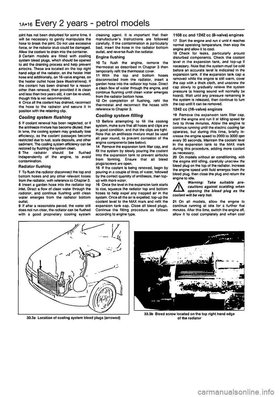
joint has not been disturbed for some time, if will bo necessary to gently manipulate the hose to break the joint. Do not use excessive force, or the radiator stub could be damaged. Allow the coolant to drain Into the container. 3 Certain models are fitted with cooling system bleed plugs, which should be opened to aid the draining process and help prevent airlocks. These are located on the top right hand edge of the radiator, on the heater Inlet hose and additionally, on 16-valve engines, on the heater outlet hose (see illustrations). If the coolant has been drained for a reason other than renewal, then provided It is ciean and less than two years old, it can be re-used, though this is not recommended. 4 Once ail the coofant has drained, reconnect the hose to the radiator and secure it in position with the retaining clip.
Cooling system flushing 5 If coolant renewal has been neglected, or If the antifreeze mixture has become diluted, then in time, Ihe cooling system may gradually lose efficiency, as the coolant passages become restricted due to rust, scale deposits, and other sediment. The cooling system efficiency can be restored by flushing the system clean. 6 The radiator should be flushed Independently of the engine, to avoid contamination. Radiator flushing 7 To flush the radiator disconnect the top and bottom hoses and any other relevant hoses from the radiator, with reference to Chapter 3. 8 Insert a garden hose into the radiator top inlet. Direct a flow of clean v/ater through the radiator, and continue flushing until clean water emerges from the radiator bottom outlet. 9 If after a reasonable period, the water still does not run clear, the radiator can be flushed wilh a good propnetary cooling system
cleaning agent. It is important that their manufacturer's Instructions are followed carefully. If the contamination is particularly bad, insert the hose in the radiator bottom outlet, and reverse-flush the radiator. Engine flushing 10 To flush the engine, remove the thermostat as described In Chapter 3 then temporarily refit the thermostat cover. 11 With the top and bottom hoses disconnected from the radiator, insert a garden hose into the radiator top hose. Direct a clean flow of water through the engine, and continue flushing until clean water emerges from the radiator bottom hose. 12 On complotion of flushing, refit the thermostat and reconnect the hoses with reference to Chapter 3,
Cooling system filling 13 Before attempting to fill the cooling system, make sure that all hoses and clips are in good condition, and that the clips are tight. Note that an antifreezo mixture must be used all year round, to prevent corrosion of the engine components (see below). 14 Remove the expansion tank filler cap. and fill the system by slowly pouring the coolant Into the oxpansion lank to prevent airlocks from forming. Ensure that all bleed plugs/screws are open. 15 If the coolant Is being renewed, begin by pouring in a couple of litres of v/ater, followed by the correct quantity of antifreeze, then top-up with more water. 16 Once the level in the expansion tank starts to rise, squeeze the radiator top and bottom hoses to help expel any trapped air In the system. Once all the air is expelled, top-up the coolant level to the MAX mark and refit the expansion tank cap. Close all bleed plugs. Continue the filling procedure as follows according to engine type.
1108 cc and 1242 cc (8-vaive) engines 17 Start the engine and run it until tt reaches normal operating temperature, then stop the engine and allow it to cool. 18 Chock for teaks, particularly around disturbed components. Check the coolant level in the expansion tank, and top-up H necessary. Note that the system must be coW before an accurate level Is indicated in the oxpansion tank. If the expansion tank cap is removed while the engine Is still warm, cover Ihe cap with a thick cloth, and unscrew the cap slowly to gradually relieve the system pressure (a hissing sound will normally be heard). Wall until any pressure remaining In the system is released, then continue to turn the cap until It can be removed. 1242 cc (16-valve) engines 19 Remove the expansion tank filler cap. start the engine and run it at Idling speed for two to three minutes. Allow the engine to continue running until the electric cooling fan operates, but during this time, briefly in-crease the engine speed to 2000 to 3000 rpm every 30 seconds. Maintain the coolant level in the expansion tank to the MAX mark during tliis procedure, adding more coolant as necessary. 20 On models without air conditfoning, wilh the engine still idling, carefully unscrew the bleed plug on the top of the radiator. Increase the engine speed until fluid emerges from the bleed plug, then close the plug and return the engine to idle.
A
Warning: Take suitable pre-cautions against scalding when opening the bleed plug as the coolant will be very hot. 21 On all models, allow the engine to continue running at idle for a further five minutes. After this time, switch the engine ofl, allow it 1o cool completely and when cool
Page 39 of 225
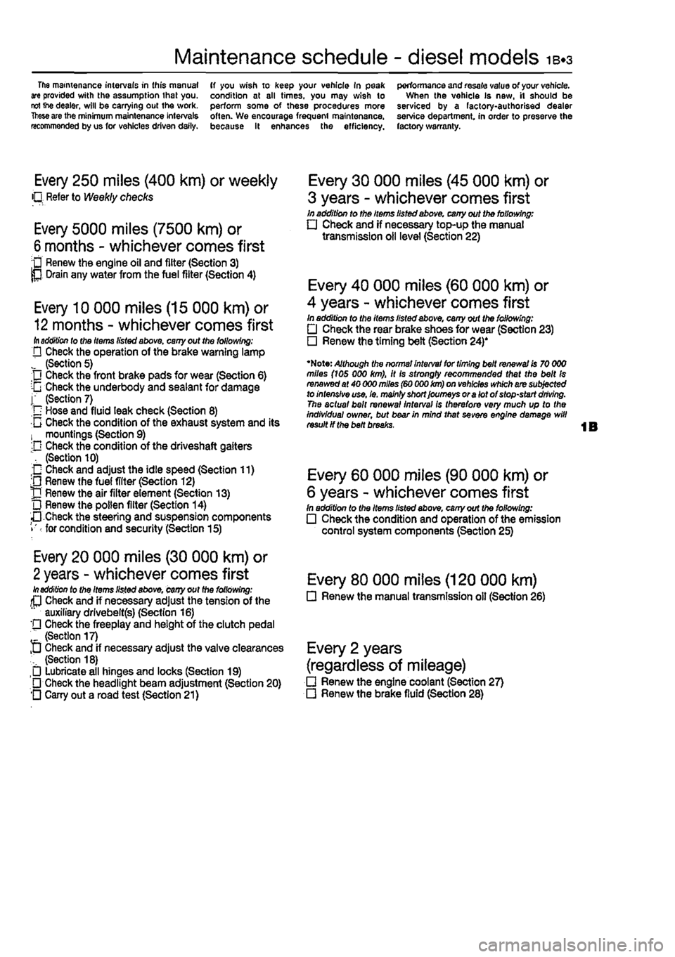
Maintenance schedule - diesel models 1B.3
The mamtenance intervals in this manual are provided with the assumption that you. reI ihe dealer, will be carrying out the work.
These
are the minimum maintenance intervals recommended by us for vehicles driven daily.
ff you wish to keep your vehicle In peak condition at all times, you may wish to perform some of these procedures more often. We encourage frequent maintenance, because it enhances the efficiency.
performance and resale value of your vehicle. When the vehicle Is new, it should be serviced by a factory-authorised dealer service department, in order to preserve the factory warranty.
Every 250 miles (400 km) or weekly O Refer to Weekly checks
Every 5000 miles (7500 km) or
6
months - whichever comes first • Renew the engine oil and filter (Section 3) P Drain any water from the fuel filter (Section 4)
Every 10 000 miles (15 000 km) or
12
months - whichever comes first ill addition lo tho Items listed above, cany out the following; D Check the operation of the brake warning lamp J (Section 5) Check the front brake pads for wear (Section 6) :-G Check the underbody and sealant for damage j" (Section 7) n Hose and fluid leak check (Section 8) 0 Check the condition of the exhaust system and its 1 mountings (Section 9) -D Check the condition of the driveshaft gaiters ", (Section 10) O Check and adjust the idle speed (Section 11) ;0 Renew (he fuel filter (Section 12) J] Renew the air filter element (Section 13) L) Renew the pollen filter (Section 14) •• Check the steering and suspension components • for condition and security (Section 15)
Every 20 000 miles (30 000 km) or
2
years - whichever comes first In addition to the Items listed above, cany out the following: (P Check and if necessary adjust the tension of the auxiliary drlvebeltfs) (Section 16) '• Check the freeplay and height of the clutch pedal " (Section 17) D Check and if necessary adjust the valve clearances (Section 18) Lubricate all hinges and locks (Section 19) • Check the headlight beam adjustment (Section 20) O Cany out a road test (Section 21)
Every 30 000 miles (45 000 km) or
3 years - whichever comes first In addition to the Items listed above, cany out the following: • Check and if necessary top-up the manual transmission oil level (Section 22)
Every 40 000 miles (60 000 km) or
4 years - whichever comes first In addition to the items listed above, cany out the following: • Check the rear brake shoes for wear (Section 23) • Renew the timing belt (Section 24)'
•Note: Although the normal interval for timing belt renewal is 70 000 miles (ids 000 km), it is strongly recommended that the belt Is renewed at 40 000 miles (60 000 km) on vehicles which are subjected to intensive use, le. mainly short Journeys or a lot of stop-start driving. The actual bait renewal interval Is therefore very much up to the Individual owner, but bear in mind that sevefe engine damage will result if the belt breaks.
Every 60 000 miles (90 000 km) or
6 years - whichever comes first In addition to the Items listed above, cany out the following: • Check the condition and operation of the emission control system components (Section 25)
Every 80 000 miles (120 000 km) • Renew the manual transmission oil (Section 26)
Every 2 years
(regardless of mileage) • Renew the engine coolant (Section 27) • Renew the brake fluid (Section 28)
Page 47 of 225
Every 20 000 miles - diesel models ib.h
18
Valve clearance check and
adjustment
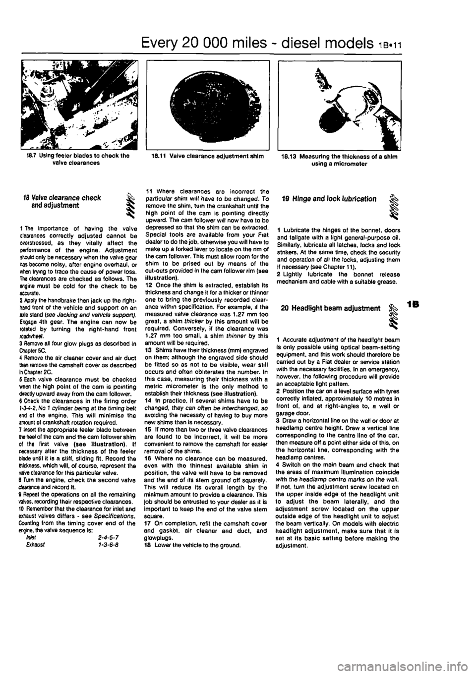
1 The Importance of having the valve clearances correctly adjusted cannot be Distressed, as they vitally affect the performance of the engine. Adjustment should only be necessary when the valve gear nas become noisy, after engine overhaul, or when trying to trace the cause of power loss. The clearances are checked as follows. The engine must be cold for the check to be ttcurate. 2 Apply the handbrake then jack up the right-hand front of the vehicle and support on an axle stand (see Jacking and vehicle support). Engage 4th gear. The engine can now be rotated by turning the right-hand front roadwfteei. 3 Remove ail four glove plugs as described In Chapter 5C. 4 Remove the air cleaner cover and air duct
then
remove the camshaft cover as described
in
Chapter 2C. 6 Each valve clearance must be checked wnen the high point of the cam is pointing directly upward away from the cam follower. 6 Check the clearances in the firing order 1-3-4-2, No 1 cylinder being at the timing belt end of the engine. This will minimise the amount of crankshaft rotation required. 7 Insert the appropriate feeler blade between
the heel
of the cam and the cam follower shim of the First valve (see Illustration). If necessary alter the thickness of the feeler blade until it is a stiff, sliding fit. Record the thickness, which will, of course, represent the
vafve
clearance tor Ihis particular valve. 8 Turn the engine, check the second valve devance and record it. t Repeat the operations on all the remaining valves. recording their respective clearances. 10 Remember that the clearance for inlet and exhaust valves differs - see Specifications. Counting from the timing cover end of the
engine,
the valve sequence is: Wef 2-4-5-7 Etfiat/sf 7-3-6-8
11 Where clearances are incorrect the particular shim will have to be changed. To remove the shim, turn the crankshaft until the high point of the cam is pointing directly upward. The cam follower will now have to bo depressed so that the shim can be extracted. Special tools are available from your Fiat dealer to do the job. otherwise you will have to make up a forked lever to locate on the rim of ihe cam follower. This must allow room for the shim to be prised out by means of the cut-outs provided in the cam follower rim (see illustration). 12 Once Ihe shim is extracted, establish Its thickness and change it for a thicker or thinner one to bring the previously recorded clear-ance within specification, For example, if the measured valve clearance was 1.27 mm too great, a shim thicker by this amount will be required. Conversely, if the clearance was 1.27 mm too small, a shim thinner by this amount will be required. 13 Shims have their thickness (mm) engraved on ihem; although the engraved side should be fitted so as not to be visible, wear still occurs and often obliterates the number. In this case, measuring their thickness with a metric micrometer is the only method to establish their thickness (see illustration). 14 In practice, if several shims have to be changed, they can often be interchanged, so avoiding the necessity of having to buy more new shims than is necessary. 15 If more than two or three valve clearances are found to be incorrect, it will be more convenient to remove the camshaft lor easier removal of the shims. 16 Where no clearance can be measured, even with the Ihinnest available shim in position, the valve will have to be removed and the end of its stem ground off squarely. This will reduce its overall length by the minimum amount to provide a clearance. This job should be entrusted to your dealer as it is important to keep the end of the valve stem square. 17 On completion, refit the camshaft cover and gasket, air cleaner and duct, and glosvplugs. 18 Lower the vehicle to the ground.
19 Hinge and lock lubrication
I
1 Lubricate the hinges of the bonnet, doors and tailgate with a light general-purpose oil. Similarly, lubricate all latches, locks and lock stnkers. At the same time, check the security and operation of all the locks, adjusting them if necessary (see Chapter 11). 2 Lightly lubricate the bonnet release mechanism and cable with a suitable grease.
20 Headlight beam adjustment
I
1 Accurate adjustment of the headlight beam Is only possible using optical beam-setting equipment, and this work should therefore be carried out by a Fiat dealer or service station with the necessary facilities. In an emergency, however, the following procedure will provide an acceptable light pattern. 2 Position the car on a level surface with tyres correctly inflated, approximately 10 metres in front of, and at right-angles to, a wall or garage door. 3 Draw a horizontal tine on the wall or door at headlamp centre height. Draw a vertical line corresponding to the centre line of the car. then measure off a point either side of this, on the horizontal line, corresponding with the headlamp centres. 4 Switch on the main beam and check that the areas of maximum Illumination coincide with the headlamp centre marks on the wall. If not, turn the adjustment screw located on the upper Inside edge of the headlight unit to adjust the beam laterally, and the adjustment screw located on the upper outside edge of the headlight unit to adjust the beam vertically. On models with electric headlight adjustment, make sure that it Is set at its basic setting before making the adjustment,
Page 49 of 225
Maintenance procedures - diesel models 1B.13
Every 60 000 miles (90 000 km) or 6 years
Refer to Chapter 40. A full chock of the 26 Emissions control systems emissions control systems must be made by a check Fiat dealer.
Every 80 000 miles (120 000 km)
26 Manual transmission ,v->> oil renewal K
1 Pak the vehicle on a level surface, if possible over an inspection pit or on a ramp as the filer/level and drain plugs are accessed from
under the
engine compartment, ff necessary tack up Ihe vehicle and support on axle stands (see Jacking and
vehicle
support). 2
Wipe
clean the area around the filler/! a vol and vain plugs, which are situated on the front and bottom of the transmission (see Illustration}.
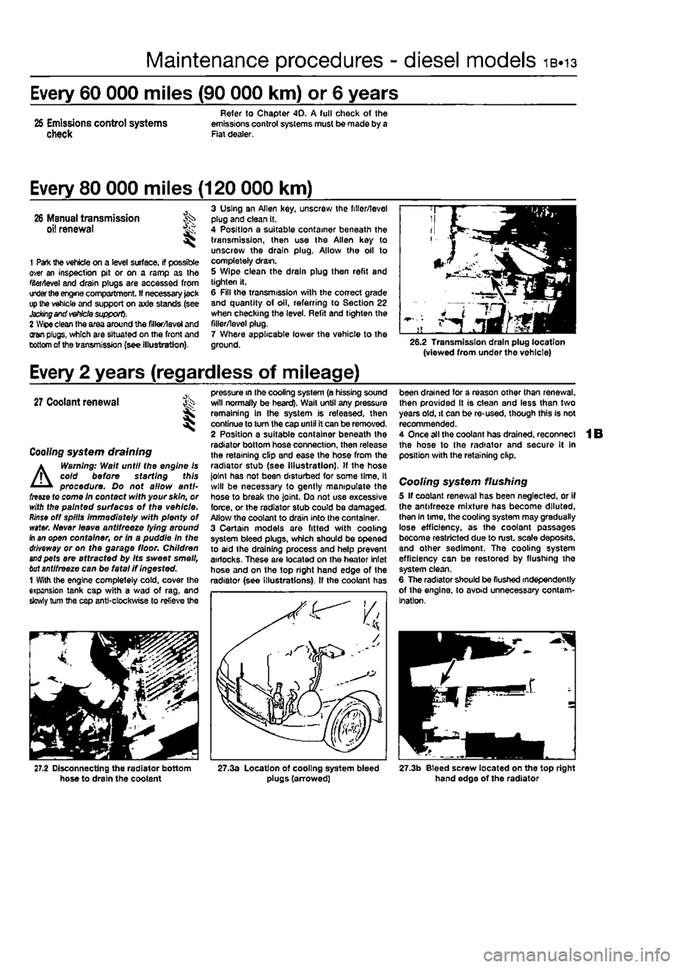
3 Using an Allen key, unscrew the fillor/level plug and clean it. 4 Position a suitable container beneath the transmission, then use the Allen key to unscrew the drain plug. Allow the oil to completely dram. 5 Wipe clean the drain plug then refit and tighten It. 6 Fill the transmission with the correct grade and quantity of oil, referring to Section 22 when checking the level. Refit and tighten the filler/level plug. 7 Where applicable lower the vehicle to the ground. 26.2 Transmission drain plug location (viewed from undor tho vohlcle)
Every 2 years (regardless of mileage)
27
Coolant renewal St I
Coo//ng system draining
A
Warning: Wait until the engine is coid before starting this procedure. Do not allow anti-fnue to come in contact with your skin, or with the painted surfaces of the vehicle.
Rinse
off spills immediately with plenty of water. Never leave antifreeze lying around fh an open container, or in a puddle in the driveway or on the garage floor. Children
and
pets are attracted by Its sweet smell,
bat
antifreeze can be fatal if ingested. 1 With the engine completely cold, cover the expansion tank cap with a wad of rag, and slowly turn the cap anti-clockwise to relieve the
pressure in the cooling system (a hissing sound will normally be heard). Wail until any pressure remaining in the system is released, then continue to turn the cap until it can be removed. 2 Position a suitable container beneath the radiator bottom hose connection, then release the retaining clip and ease the hose from the radiator stub (see Illustration), If the hose joint has not been disturbed for some time, it will be necessary to gently manipulate the hose to break the joint. Do not use excessive force, or the radiator stub could be damaged. Allow the coolant to drain into the container. 3 Certain models are fitted with cooling system bleed plugs, which should be opened to aid the draining process and help prevent airlocks. These are located on the heator Inlet hose and on the top right hand edge of the radiator (see Illustrations), ff the coolant has
been drained for a reason other than renewal, then provided It is clean and less than two years old, it can be re-used, though this is not recommended. 4 Once all the coolant has drained, reconnect the hose to the radiator and secure it in position with the retaining clip.
Cooling system flushing 5 If coolant renewal has been neglected, or if the antifreeze mixture has become diluted, then In time, the cooling system may gradually lose efficiency, as the coolant passages become restricted due to rust, scale deposits, and other sediment. The cooling system efficiency can be restored by flushing tho system clean. 6 The radiator should be (lushed independently of the engine, to avoid unnecessary contam-ination.
27.2 Disconnecting the radiator bottom hose to drain the coolant 27.3a Location of cooling system bleed plugs (arrowed) 27.3b Bleed screw located on the top right hand edge of the radiator
Page 50 of 225
ib.14 Every 2 years - diesel models
Radiator flushing 7 To flush the radiator disconnect the top and bottom hoses and any other relevant hoses from the radiator, with reference to Chapter 3. 8 Insert a garden hose into the radiator top inlet. Direct a flow of dean water through the radiator, and continue Hushing until clean water emerges from the radiator bottom outlet. 9 II after a reasonable period, the water still does not run clear, the radiator can be flushed with a good proprietary cooling system cleaning agent. It is important that their manufacturer's instructions are followed carefully. If Ihe contamination is particularly bad, insert the hose in the radiator bottom outlet, and reverse-flush the radiator.
Engine flushing 10 To flush tho engine, remove the thermostat as described in Chapter 3. 11 With the bottom hose disconnected, direct a clean flow of water through the engine, and continue Hushing until clean water emerges from the radiator bottom hose. 12 On completion of flushing, refit the thermostat and reconnect the hose with reference to Chapter 3.
Cooling system filling 13 Before attempting to fill the cooling system, make sure that all hoses and clips are in good condition, and that the clips are tight. Note that an antifreeze mixture must be used all year round, to prevent corrosion of the engine components (see following sub* Section). 14 Remove the expansion tank filler cap. and fill the system by slowly pouring the coolant Into Ihe expansion tank to prevent airlocks from forming. Ensure that all bleed plugs/screws are open. 15 If the coolant is being renewed, begin by pouring in a couple of litres of water, followed by the correct quantity of antifreeze, then top* up with more water. 18 Once ihe level in the expansion tank starts to rise, squeeze the radiator top and bottom hoses to help expel any trapped air in
the system. Once all the air is expelled, top-up the coolant level to the MAX mark and refit the expansion tank cap. Close all bleed plugs. 17 Start Ihe engine and run il until it reaches normal operating temperature, then stop the engine and allow It to cool. 18 Check for leaks, particularly around disturbed components. Check the coolant level In the expansion tank, and top-up if necessary. Note that the system must be cold before an accurate level Is indicated In the expansion tank. If the expansion tank cap Is removed while the engine is still warm, cover the cap with a thick cloth, and unscrew the cap slowly to gradually relieve the system pressure (a hissing sound will normally be heard). Wait until any pressure remaining in the system Is released, then continue to turn the cap untH it can be removed.
Antifreeze mixture 19 The antifreeze should always be renewed at the specified intervals. This is necessary not only to maintain the antifreeze properties, but also to prevent corrosion which would otherwise occur as the corrosion Inhibitors become progressively less effective. 20 Always use an ethylene-glycol based antifreeze which is suitable for use in mixed-metal cooling systems. The quantity of antifreeze and levels of protection are indicated in the Specifications. 21 Before adding antifreeze, the cooling system should be complelely drained, preferably flushed, and all hoses checked for condition and security. 22 After filling with antifreeze, a label should be attached to the expansion tank, stating the type and concentration of antifreeze used, and the dale installed. Any subsequent topping-up should bs made with the same type and concentration of antifreeze. 23 Do not use engine antifreeze In the windscreen/tailgate washer system, as it will cause damage to the vehicle paintwork. A screenwash additive should be added to the washer system in the quantities stated on the bottle.
28 Brake fluid renewal
A
Warning: Brake hydraulic fluid can harm your eyas and damage painted surfaces, so use extreme caution when handling and pouring It. Do not use fluid that has been standing open for some time, as It absorbs moisture from the air. Excess moisture can causa a dangerous loss of braking effectiveness. 1 The procedure is similar to that for the bleeding of the hydraulic system as described In Chapter 9. except that the brake fluid reservoir should be emptied by siphoning, using a clean poultry baster or similar before starting, and allowance should be made for the old fluid to be expelled when bleeding a section of the circuit. 2 Working as described in Chapter 9, open Ihe first bleed screw in the sequence, and pump the brake pedal gently until nearly all the old fluid has been emptied from the master cylinder reservoir.
ffffTOgf Old hydraulic fluid Is
lifcjllitt*
Invariably much darker In [HINT] colour than the new, making /{easy to distinguish the two.
3 Top-up to the MAX level with new fluid, and continue pumping until only the new fluid remains in the reservoir, and new fluid can be seen emerging from (he bleed screw. Tighten the screw, and top the reservoir level up to Ihe MAX level line. 4 Work through all the remaining bleed screws In the sequence until new fluid can be seen al all of them. Be careful to keep the master cylinder reservoir topped-up 10 above the MIN level al all limes, or air may enter the system and greatly increase the length of the task. 5 When the operation is complete, check thai all bleed screws are securely tightened, and that their dust caps are refitted. Wash off ail traces of split fluid, and recheck the master cylinder reservoir fluid level. 6 Check the operation of the brakes before taking the car on the road,
Page 74 of 225
2C*2 Diesel engine in-car repair procedures
1 General information
Using this Chapter Chapter 2 is divided Into four Parts; A. 8, C and 0. Repair operations that cart be carried out with the engine in the vehicle are described In Part A, SOHC (B-valve) petrol engines. Part B, DOHC (16-valve) petrol engines and Part C. diesel engines, Part D covers the removal of the engine/transmission as a unit, and describes the engine dismantling and overhaul procedures. In Parts A. 8 and C. the assumption Is made that the engine is installed in Ihe vehicle, with all anciliaries connected If the engine has been removed for overhaul, the preliminary dismantling information which precedes each operation may be ignored.
Engine description Both normally aspirated (non-turbo) and turbocharged diesel engines are fitted to the Punto range. The engines together with their codes are given in the Specifications at the start of lhis Chapter. The engines are water-cooled, single-overhead camshaft. In-line lour cylinder units with cast-iron cylinder blocks and aluminium-alloy cylinder heads. The engine is mounted transversely at the front of the vehicle, with the transmission bolted to the left-hand side of the engine. The cylinder head carries the camshaft which is driven by a toothed timing belt. It also houses the inlet and exhaust valves which are closed by single coll valve springs and run in valve guides pressed into the cylinder head. The valves are operated by cam followers fitted over each valve, and the clearances are adjusted by shims positioned between the followers and the camshaft lobes. The camshaft is supported by four bearings • the end bearings are machined in the cylinder head and the remaining bearings have caps bolted to the cylinder head. The cylinder head contains integral oiiways which supply and lubricate the camshaft and followers and it also Incorporates renewable swirl chambers. The crankshaft Is supported by five main bearings, and endfloat Is controlled by a thrust bearing fitted on the rear main bearing. All diesel engines are fitted with a brake servo vacuum pump dnven from the left-hBnd end of the camshaft. Engine coolant is circulated by a pump, driven by the auxiliary drivebeit. For details of the cooling system refer to Chapter 3. Lubricant is circulated under pressure by a pump, driven from the front of the crankshaft. Oil is drawn from the sump through a strainer, and then forced through an externally-mounted, replaceable screw-on filter. From there, it is distributed to the cylinder head.
where il lubncates the camshaft journals and followers, and also to the crankcase, where it lubricates the main bearings, connecting rod big- and small-ends, gudgeon pins and cylinder bores. Oil jets are fitted to the base of each cylinder bore - these spray oil onto the underside of the pistons, lo Improve cooling. An oil cooler is also fitted to reduce the temp-erature of oil before it re-enters the engine.
Repair operations possible with the engine in the car The following work can be carried out with the engine in the can a) Compression pressure - testing b) Auxiliary drivebeit - removal and refitting (refer to Chapter rej c) Valve clearances • checking and adjustment (refer to Chapter 1B) d) Camshaft cover - removal and refitting e) Tim/ng belt and covers • removal and refitting 0 Timing belt tensioner and sprockets -removal and refitting g) Cylinder head - removal and refitting' h) Camshaft and cam followers - removal end refitting' I) Camshaft oil seal - renewal j) Crankshaft oil seals - renewal k) Flywheel • removal, inspection and refitting I) Engine mountings - inspection and renewal m)Sump • removal and refitting n) Oil pump and pick-up tube assembly -removal, inspection and refitting 'Cylinder head dismantling procedures are detalfed In Chapter 2D, with details of camshaft and cam follower removal. Note: It ts possible to remove the pistons and connecting rods (after removing the cylinder nead and sump) without removing the engine. However, this is not recommended. Work of this nature is more easily and thoroughly completed with the engine on tho bench as described in Chapter 2D.
2 Location of
TDC
on ^ No
1
cylinder ||
General information 1 The camshaft and fuel Injection pump are driven by the crankshaft, by means of sprockets and a timing belt. All three sprockets rotate in phase with each other and this provides the correct valve and injection pump timing as the engine rotates. When the timing bell is removed during servicing or repair, it is possible for the camshaft, injection pump and crankshaft to rotate independently of each other and the correct timing Is then lost.
2 It
Location of TDC on cylinder No
1
6 Remove the air inlet ducting as described ft Chapter 4C, Section 2. 7 Remove the heater glow plugs with reference to Chapter 5C. Due to the high compression ratio of diesel engines this Is necessary to allow the engine to be turned by hand. 8 Unscrew the mounting bolts and move the coolant expansion tank to one side for access to the timing covers. Release the hose from the clips on Ihe camshaft cover. 9 Release the toggle clips and remove the upper timing cover (see illustration),
2.9 Removing the upper timing cover
Page 91 of 225
2D*10 Engine removal and overhaul procedures
1 General information
Included In (his Part of Chapter 2 are details of removing the engine/transmission from the car and general overhaul procedures for tho cylinder head, cylinder block/crankca9e and all other engine internal components. The information given ranges from advice concerning preparation for an overhaul and the purchase of replacement parts, to detailed step-by-step procedures covering removal, inspection, renovation and refitting of engine Internal components. After Section 5, all instructions are based on the assumption that the engine has been removed from the car. For Information concerning in-car engine repair, as well as the removal and refitting of those external components necessary for full overhaul, refer to Part A, 8 or C of this Chapter (as applicable) and to Section 5. Ignore any preliminary dismantling operations described in Part A. B or C that are no longer relevant onca the engine has been removed from ihe car.
2 Engine overhaul -general information
1 It Is not always easy to determine when, or if, an engine should be completely overhauled, as a number of lectors must be considered. 2 High mileage Is not necessarily an Indication that an overhaul Is needed, while low mileage does not preclude the need for an overhaul. Frequency of servicing Is probably the most important consideration. An engine which has had regular and frequent oil and filter changes, as well as other required maintenance, should give many thousands of miles of reliable service. Conversely, a neglected engine may require an overhaul very early In its life. 3 Excessive oil consumption Is an Indication that piston rings, vaivo seals and/or valve guides are in need of attention. Make sure that oil leaks are not responsible before deciding that the rings and/or guides are worn Perform a compression test, as described In Parts A or B (petrol engines) or C (diesel engines) of this Chapter, to determine the likely cause of the problem. 4 Check the oil pressure with a gauge fitted In place of the oil pressure switch. If it Is extremely low. the main and big-end bearings, and/or the oil pump, are probably worn out. 5 Loss of power, rough running, knocking or metallic engine noises, excessive valve gear noise, and high fuel consumption may also point to Ihe need for an overhaul, especially if
they are all present at the same time. If a complete service does not remedy the situation, major mechanical work is the only solution. 6 An engine overhaul involves restoring ell Internal parts to the specification of a new engine. During an overhaul, the cylinders are rebored (where applicable), the pistons and the piston rings are renewed. New main and big-end bearings are generally fitted; If necessary, the crankshaft may be reground. to restore the journals. 7 The valves are also servrced as well, since they are usually In less-than-perfect condition at this point. While the engine is being overhauled, other components, such as the starter and alternator, can be overhauled as well. The end result should be an as-new engine that will give many trouble-free miles. Note: Critical cooling system components such as the hoses, thermostat and coolant pump should be renewed when an engine is overhauled. The radiator should be checked carefully, to ensure that it is not clogged or leaking. A/so. it Is a good Idea to renew the ofI pump whenever the engine i$ overhauled.
8 Before beginning the engine overhaul, read through tho entire procedure, to familiarise yourself with the scope and requirements of the job. Overhauling an engine is not difficult If you follow carefully all of the instructions, have the necessary tools and equipment, and pay close attention to all specifications. It can, however, be time-consuming. Plan on the car being off the road for a minimum of two weeks, especially If pans must be taken to an engineering wo'kd for repair or reconditioning.
9 Check on the availability of parts and make sure that any necessary special tools and equipment are obtained in advance. Most work can be done with typical hand lools, although a number of precision measuring tools are required (or Inspecting parts to determine if they must be renewed. Often the engineering works will handle the inspection of parts and offer advice concerning reconditioning and renewal, Note: Always wait unt'l the engine has been completely dismantled, and until all components (especially the cylinder block/crankcase and the crankshaft) have been inspected, before deciding what service and repair operations must be performed by an engineering works. The condition of these components will be the major factor to consider when determining whether to overhaul the original engine, or to buy a reconditioned unit. Do not. fh ere tore, purchase parts or have overhaul work done on other components until they have been thoroughly Inspected. As a general rule, time is the primary cost of an overhaul, so it does not pay to fit worn or sub-standard parts.
10 As a final note, to ensure maximum life and minimum trouble from a reconditioned engine, everything must be assembled wilh care, in a spotlessly-clean environment.
3 Engine and transmission removal -methods
and
precautions
1 If you have decided that the engine must be removed for overhaul or major repair work, several preliminary steps should be taken. 2 Locating a suitable place to work is extremely important. Adequate work space, along with storage space for the car, will be needed. If a workshop or garage Is not available, at the very least, a flat, level, clean work surface Is required. 3 Cleaning the engine compartment and engine/transmission before beginning the removal procedure wilt help keep tools clean and organised. 4 An engine hoist or A-frame will also be necessary. Make sure the equipment is rated In excess of the combined weight of the engine and transmission, Safety Ib of primary Importance, considering the potential hazards involved in lifting the engine/transmission out of the car. 5 If this is Ihe first time you have removed
an
engine, an assistant Bhould Ideally be available. Advice and aid from someone more experienced would also be helpful. There are many instances when one person cannot simultaneously perform all of the operations required when lifting the engine out of Ihe vehicle. 6 Plan the operation ahead of time. Before starting work, arrange for the hire of or obtain all of the tools and equipment you will need. Some of the equipment necessary to perform engine/transmission removal and Installation safely and wilh relative ease On addition to an engine hoist) Is as follows: a heavy duly trolley jack, complete sets of spanners and sockets as described in the reference section of this manual, wooden blocks, and plenty of rags and cleaning solvent for mopping up spitted oil, coolant and fuel. If the hoist must be hired, make sure that you arrange for it In advance, and perform all of the operations possible without it beforehand. This will save you money and time.
7 Plan for the car to be out of use for quite a while. An engineering works will be required to perform some of the work which the do-it-yourselfer cannot accomplish without special equipment. These places often have a busy schedule, so it would be a good idea to consul! them before removing the engine, in order to accurately estimate the amount of time required to rebuild or repair components that may need work, 9 Always be extremely careful when removing and refitting the engine/transmission. Serious injury can result from careless actions. Plan ahead and take your time, and a job of this nature, although major, can be accomplished successfully.