steering wheel FIAT PUNTO 1999 176 / 1.G User Guide
[x] Cancel search | Manufacturer: FIAT, Model Year: 1999, Model line: PUNTO, Model: FIAT PUNTO 1999 176 / 1.GPages: 225, PDF Size: 18.54 MB
Page 38 of 225
1B.2
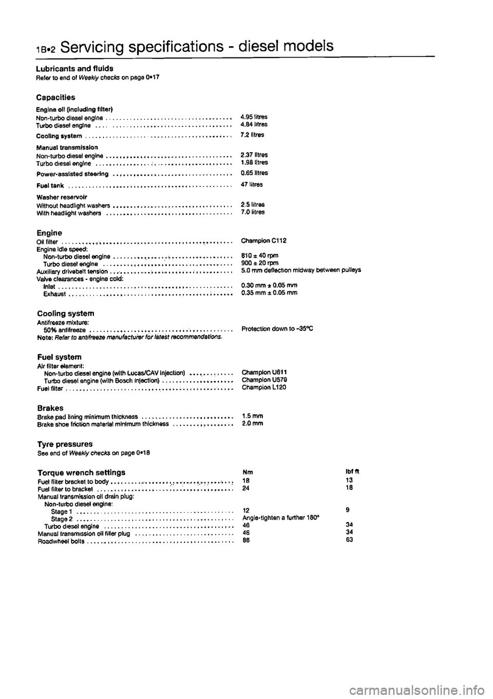
Servicing specifications - diesel models
Lubricants and fluids Refer to end of Weekly checks on page 0*17
Capacities Engine oil (including filter) Non-turbo diesei engine 4.95 litres Turbo diesel engine 4.84 litres Cooling system 7.2 litres
Manual transmission Non-turbo diesel engine 2.37 litres Turbo diesei engine t .98 litres Power-assisted steering 0.65 litres
Fuel tank 47 litres Washer reservoir Without headlight washers 2.5 litres With headlight washers 7.0 litres
Engine Oil fitter Engine Idle speed: Non-turbo diesel engine Turbo diesel engine Auxiliary drivebelt tension ...... Valve clearances • engine cold: Inlet Exhaust
Champion C112
8l0«40rpm 900 ± 20 rpm 5.0 mm deflection midway between pulleys
0.30 mm * 0.05 mm 0.35 mm ± 0.05 mm
Cooling system Antifreeze mixture: 50% antifreeze Protection down to-35°C Note: Refer to antifreeze manufactuivr for latest recommendations.
Fuel system Air filter element: Non-turbo diesel engine (with Lucas/CAV Injection) Champion U611 Turbo diesel engine (with Bosch Injection) Champion U579 Fuel filter Champion L120
Brakes Brake pad lining minimum thickness 1-5 mm Brake shoe friction material minimum thickness 2.0 mm
Tyre pressures See end of Weekly checks on page 0*18
Torque wrench settings Fuel filter bracket to body ..... « Fuel filter to bracket i........ Manual transmission oil drain plug: Non-turbo diesel engine: Stage 1 Stage 2 Turbo diesel engine Manual transmission oil filler plug Roadwheel bolts
Nm Ibfft 18 13 24 18
12 9 Angle-tighten a further 180® 46 34 46 34
Page 43 of 225
Maintenance procedures - diesel models ib.?
Every 10 000 miles (15 000 km) or 12 months
5 Brake warning lamp operation check 1
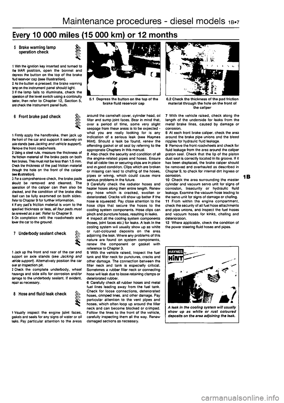
1 With Ihe ignition Key inserted and turned to the MAR position, open the bonnet and depress the button on the top of the brake
fluid
reservoir cap (see illustration). I
As
the button is pressed, the brake warning
lamp
on the instrument panel should light. 3 If Ihe lamp fails to illuminate, check the operation of the level switch using a continuity taster, then refer to Chapter t2, Section 5,
and
check the Instrument panel bulb.
6 Front brake pad check ^
I
1 firmly apply Ihe handbrake, then jack up the front of the car and support it securely on arie stands (see Jacking and vehicle support). Remove the front roadwheels. 2 Using a steel rule, measure the thickness of
the
friction material of the brake pads on both brakes. This must not be less than 1.5 mm. Ctefc the thickness of the pad friction material through the hole on the front of the caliper
|see
lustration), 3
For a
comprehensive check, the brake pads should be removed and cleaned. The operation of the caliper can then also bo checked, and the condition of the brake disc iteeil can be fully examined on both sides. Refer to Chapter 9 for further Information. 4 If any pad's friction material Is worn to the specified thickness or less, all lour pads must to renewed as a set. Refer to Chapter 9. 5 On completion refit the roadwheels and lower the car to the ground.
7 Underbody sealant check f^
1 Jack up the front and rear of the car and support on axle stands (see Jacking and
vehicle
support). Alternatively position the car over
an
Inspection pit. 2 Check the complete underbody, wheel housings and side sills for corrosion and/or damage to the underbody sealant. If evident,
rapairi
8
Hose
and fluid leak check
1 Visually inspect the engine Joint faces. g3skets and seals for any signs of water or oil leaks. Pay particular attention to the areas
5.1 Depress tho button on the top of the brake fluid reservoir cap
around the camshaft cover, cylinder head, oil filter and sump joint faces. Bear in mind that, over a period of time, some very slight seepage from these areas is to be expected -what you are really looking for is any indication of a serious leak (see Haynes Hint). Should a teak be found, renew the offending gasket or oil seal by referring to the appropriate Chapters In this manual, 2 Also check the security and condition of all the engine-related pipes and hoses. Ensure thai all cable-ties or securing clips are In place and in good condition. Clips which are broken or missing can lead to chafing of the hoses, pipes or wiring, which could cause more serious problems In the future. 3 Carefully check the radiator hoses and heater hoses along their entire length. Renew any hose which is cracked, swollen or deteriorated. Cracks will show up better If the hose is squeezed. Pay close attention to the hose clips that secure the hoses to the cooling system components. Hose clips can pinch and puncture hoses, resulting in leaks. 4 Inspect all the cooling system components (hoses. )olnt faces etc.) for leaks. A leak in the cooling system will usually show up as white or rust-coloured deposits on the area adjoining the leak, Where any problems of this nature are found on system components, renew the component or gasket with reference to Chapter 3. 5 With the vehicle raised, inspect the fuel tank and filler neck for punctures, cracks and other damage, The connection between the filler neck and tank is especially critical. Sometimes a rubber filler neck or connecting hose will leak due to loose retaining clamps or deteriorated rubber. 6 Carefully check all rubber hoses and metal fuel lines leading away from the fuel tank. Check for loose connections, deteriorated hoses, crimped lines, and other damage. Pay particular attention to the vent pipes and hoses, which often loop up around the filler neck and can become blocked or crimped. Follow the lines to the front of the vehicle, carefully Inspecting them all the way. Renew damaged sections as necessary.
6.2 Check the thickness of the pad friction material through the hote on the front of the caliper
7 With the vehicle raised, check along the length of the underside for leaks from the metal brake lines, caused by damage or corrosion. 8 At each front brake caliper, check the area around the brake pipe unions and the bleed nipples for hydraulic fluid leakage, 9 Remove the front roadwheels and chock for fluid leakage from the area around the caliper piston seal. Check that the tip of the piston dust seal is correctly located in its groove. If it has been displaced, the brake caliper should be removed and overhauled as described in Chapter 9, to check for internal dirt Ingress or corrosion. 10 Check the area surrounding the master cylinder and vacuum servo unit for signs of corrosion, Insecurity or hydraulic fluid leakage. Examine the vacuum hose leading to the servo unit for signs of damage or chafing. 11 From within the engine compartment, check the security of all fuel hose attachments and pipe unions, and Inspect the fuel hoses and vacuum hoses for kinks, chafing and deterioration. 12 Where applicable, check the condition of the power steering fluid hoses and pipes.
A leak in the cooling system will usually show up as white or rust coloured deposits on the area adjoining the leak.
Page 44 of 225
ib-8 Every 10 000 miles - diesel models
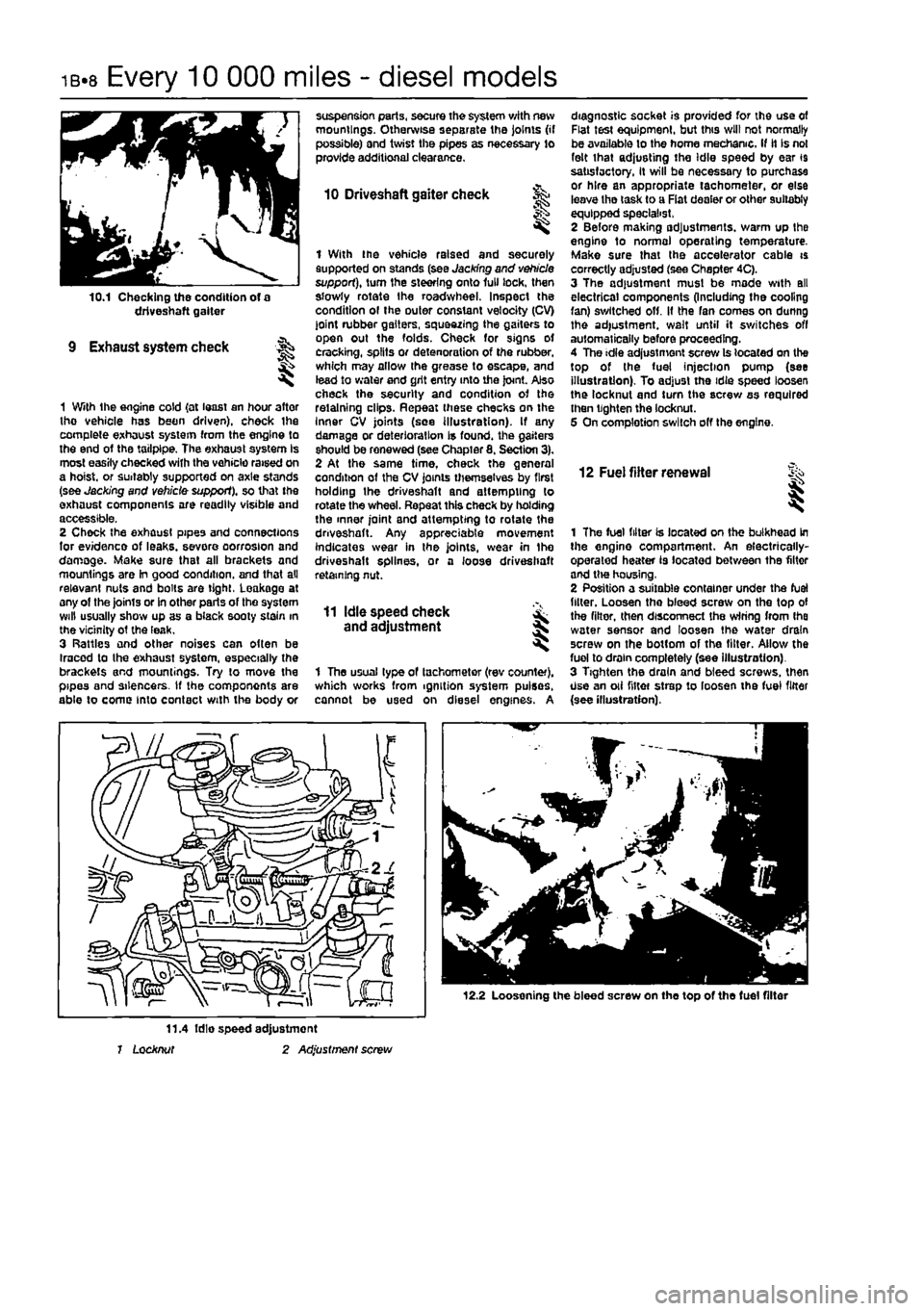
10.1 Checking the condition of a driveshaft gaiter
9 Exhaust system check
1 With the engine cold {at least an hour after tho vehicle has been driven), check ihe complete exhaust system from the engine to the end of the tailpipe. The exhaust system Is most easily checked with the vehicle raised on a hoist, or suitably supported on axle stands (see Jacking and vehicle support), so that the exhaust components are readily visible and accessible. 2 Check the exhaust pipes and connections for evidence of leaks, severe oorrosion and damage. Make sure that all brackets and mountings are In good condition, and that all relevant nuts and bolts are tight, Leakage at any of the joints or in other parts of tho system will usually show up as a black sooty stain in the vicinity ot the leak. 3 Rattles and other noises can often be Iracod to the exhaust system, especially the brackets and mountings. Try to move the pipes and silencers. If the components are able to come into contact with the body or
suspension parts, secure the system with new mountings. Otherwise separate the joints (if possible) and twist the pipes as necessary to provide additional clearance.
10 Driveshaft gaiter check
I
1 With the vehicle raised and securely supported on stands (see Jacking and vehicle support), turn the steering onto lull lock, then slowly rotate the roadwheel. Inspect the condition ol the outer constant velocity (CV) joint rubber gaiters, squeezing the gaiters to open out the folds. Check for signs ot cracking, splits or detenoration of the rubber, which may allow the grease to escape, and lead to water and grit entry into the joint. Also check the security and condition of the retaining clips. Repeat these checks on the Inner CV joints (see illustration). If any damage or deterioration is found, the gaiters should be renewed (see Chapter 8. Section 3). 2 At the same time, check the general condition of the CV joints themselves by first holding the driveshaft and attempting to rotate the wheel. Repeat this check by holding the inner joint and attempting to rotate the driveshaft. Any appreciable movement indicates wear in the joints, wear in Ihe driveshaft splines, or a loose driveshaft retaining nut.
11 Idle speed check and adjustment
1 The usual type of tachometer (rev counter), which works from ignition system pulses, cannot be used on diesel engines. A
diagnostic socket is provided for the use of Flat test equipment, but this will not normally be available to the home mechanic. If it Is not felt that adjusting the Idle speed by ear 19 satisfactory, It will be necessary to purchase or hire an appropriate tachometer, or else leave tho task to a Fiat dealer or other suitably equipped specialist, 2 Before making adjustments, warm up the engine to normal operating temperature. Make sure that the accelerator cable is correctly adjusted (see Chapter 4C). 3 The adjustment must be made with all electrical components (Including the cooling fan) switched off. It the fan comes on dunng the adjustment, wait until it switches off automatically before proceeding. 4 The idle adjustment screw Is located on the top of the fuel injection pump (see illustration). To adjust the idie speed loosen the locknut and turn the screw as required then tighten the locknut. 5 On completion switch off the engine.
12 Fuel filter renewal i
1 The fuel filter is located on the bulkhead in the engine compartment. An electrically-operated heater is located between the filter and tlw housing, 2 Position a suitable container under the fuel filler. Loosen tho bleed screw on the top of the filter, then disconnect the wiring from Ihe water sensor and loosen the water drain screw on the bottom of the filter. Allow the fuel to drain completely (see illustration). 3 Tighten the drain and bleed screws, then Use an oii niter strep to loosen the fuel filter {see illustration).
12.2 Loosening the bleed screw on the top of the fuel filter
11.4 fdie speed adjustment 1 Locknut 2 Adjustment screw
Page 45 of 225
Every 10 000 miles - diesel models ib«9
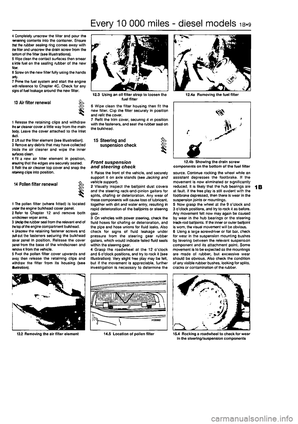
4 Completely unscrew the filter and pour the remaining contents into the container. Ensure (hat the rubber sealing ring comes away with
me
fitter and unscrew the drain screw from the
bottom
of tho filter (see illustrations). 5 Wipe clean the contact surfaces then smear
a
ittfe fuel on the sealing rubber of the new Nter. 6 Screw on the new filter fully using the hands orty. 7 Prime the fuel system and start the engine wth reference to Chapter 4C. Check for any signs of fuel leakage around the new filter.
13 Air fitter renewal
t Release the retaining clips and withdraw
Ihe
air cleaner cover a little way from the main body. Leave the cover attached to the inlet duct. 2 Lift out the filter element (see illustration). 3 Remove any debris that may have collected Inside the air cleaner and wipe the Inner surfaces clean. 4 Fit a new air filter element in position, ensuring that the edges are securely seated. 6 Refit the air cleaner top cover and snap the retaining clips into position.
14 Pollen filter renewal
t
1 The pollen filter (where fitted) Is located under the engine bulkhead cover pane). 2 Refer to Chapter 12 and remove both windscreen wiper arms. 3 Undp tho rubber seal from the relevant end of
the top
of the engine compartment bulkhead. 4 Unscrew the retaining fastener screws and Duiout the fasteners securing the bulkhead eovar panel in position. Release the cover panel from the base of the windscreen and remove it from the vehicle. 5 Pivot the pollen filter cover upwards and away then release the retaining clips and withdraw the filter from Its housing (see lustration).
12.3 Using an olt filter strap to loosen the fuel filter 6 Wipe clean the filter housing then fit the new filter, Clip the filter securely In position and refit the cover. 7 Refit the trim cover, secunng it >n position with the fasteners, and seat Ihe rubber seal on the bulkhead.
12.4a Removing the fuel filter
15 Steering and §S> suspension check ^
Front suspension and steering check 1 Raise the front of the vehicle, and securely support it on axle stands (see Jacking and vehicle support). 2 Visually Inspect the balljoint dust covers and the steering rack-and-pinion gaiters for splits, chafing or deterioration. Any wear of Ihese components will cause loss of lubricant, together with dirt and water entry, resulting in rapid deterioration of the balljoints or steering gear. 3 On vehicles with power steering, check the fluid hoses for chafing or deterioration, and the pipe and hose unions for fluid leaks. Also check for signs of fluid leakage under pressure from the steering gear rubber gaiters, which would indicate failed fluid seals within the steenng gear. 4 Grasp the roadwheel at the 12 o'clock and 6 o'clock positions, and try to rock it (see illustration). Very slight free play may be felt, but if the movement is appreciable, further investigation is necessary to determine the
fplllll iHpjiiisisps fa^aJw a LJgr >
H58B92
12.4b Showing the drain screw components on the bottom of the fuel filter source. Continue rocking the wheel while an assistant depresses the footbrake. If the movement Is now eliminated or significantly reduced, it is likely that the hub bearings are at fault. If the free ptay is still evident with the footbrake depressed, then there Is wear In the suspension joints or mountings. 5 Now grasp the wheel at the 9 o'clock and 3 o'clock positions, and try to rock it as before. Any movement felt now may again be caused by wear in the hub bearings or the steering track-rod balljoints. If the inner or outer balljoint Is worn, the visual movemont will be obvious. 6 Using a large screwdriver or flat bar. check for wear in the suspension mounting bushes by levering between the relevant suspension component and its attachment point. Some movement is to be expected as the mountings are made of rubber, but excessive wear should be obvious. Also check the condition of any visible rubber bushes, looking for splits, cracks or contamination of the rubber.
13.2 Removing the air filter element 14.5 Location of pollen filter 15.4 Rocking a roadwheel to check for wear in the steering/suspension components
Page 46 of 225
ib-io Every 10 000 miles - diesel models
7 With the car standing on Its wheels, have an assistant turn the steering wheel back and forth about an eighth of a turn each way. There should be very hide. If any, lost movement between the steering wheel and roadwheels. If this is not the case, closely observe the joints and mountings previously described, but in addition, check the steering column universal joints for wear, and the rack-and-plnion steering gear itself.
Suspension strut/ shock absorber check 8 Check for any signs of fluid leakage around the suspension strut/shock absorber body, or from the rubber gaiter around the piston rod, Should any fluid be noticed, the suspension strut/shock absorber is defective Internally, and should be renewed. Note: Suspension struts/shock absorbers should always be renewed in pairs on the same axle.
9 The efficiency of the suspension strut/shock] absorber may be checked by bouncing 0*1 vehicle at each comer. Generally speaking. th»| body will return to its normal position and 8top| after being depressed. If It rises and returns cn| a rebound, the suspension strut/shocH absorber is probably suspect. Examine also* the suspension strut/shock absorber uppeij and lower mountings for any signs of wear.
Every 20 000 miles (30 000 km) or 2 years
18 Auxiliary drivebeltfs) % check and renewal
Note: Fiat specify the use of a spec/a/ toot to correctly set the drivebelt fens/on. if access to this equipment cannot be obtained, an approximate setting can be achieved using the method described beiow. If the method described Is used, the tension should be checked using the spec/a/ too! at the earliest possible opportunity. 1 Depending on equipment fitted, one, two or three auxiliary drivebeits may be fitted. The alternator, power steering pump and air conditioning compressor, as applicable, are each driven by an individual drivebelt. Checking 2 Disconnect the battery negative terminal (refer to Disconnecting the battery In the Reference Section of this manual). 3 Firmly apply the handbrake, then Jack up the Iront of the car and support it securely on exie stands (see Jacking and vehicle support). 4 Remove the right-hand wheel. 5 Remove the Inner cover(s) from under the right-hand wheelarch for access to the right-hand side of the engine. 6 Using a socket on the crankshaft sprocket bolt, rotate the crankshaft so that the full length of the auxiliary drivebelt(s) can be examined. Look for cracks, splitting and fraying on the surface of the belt: check also for signs of glazing (shiny patches) and
16.10a Loosening the alternator drivebelt adjustment bolt
separation of the belt plies. If damage or wear Is visible, the bell should be renewed, 7 If the condition of the belt Is satisfactory, check tho drivebelt tension as described below.
Renewal
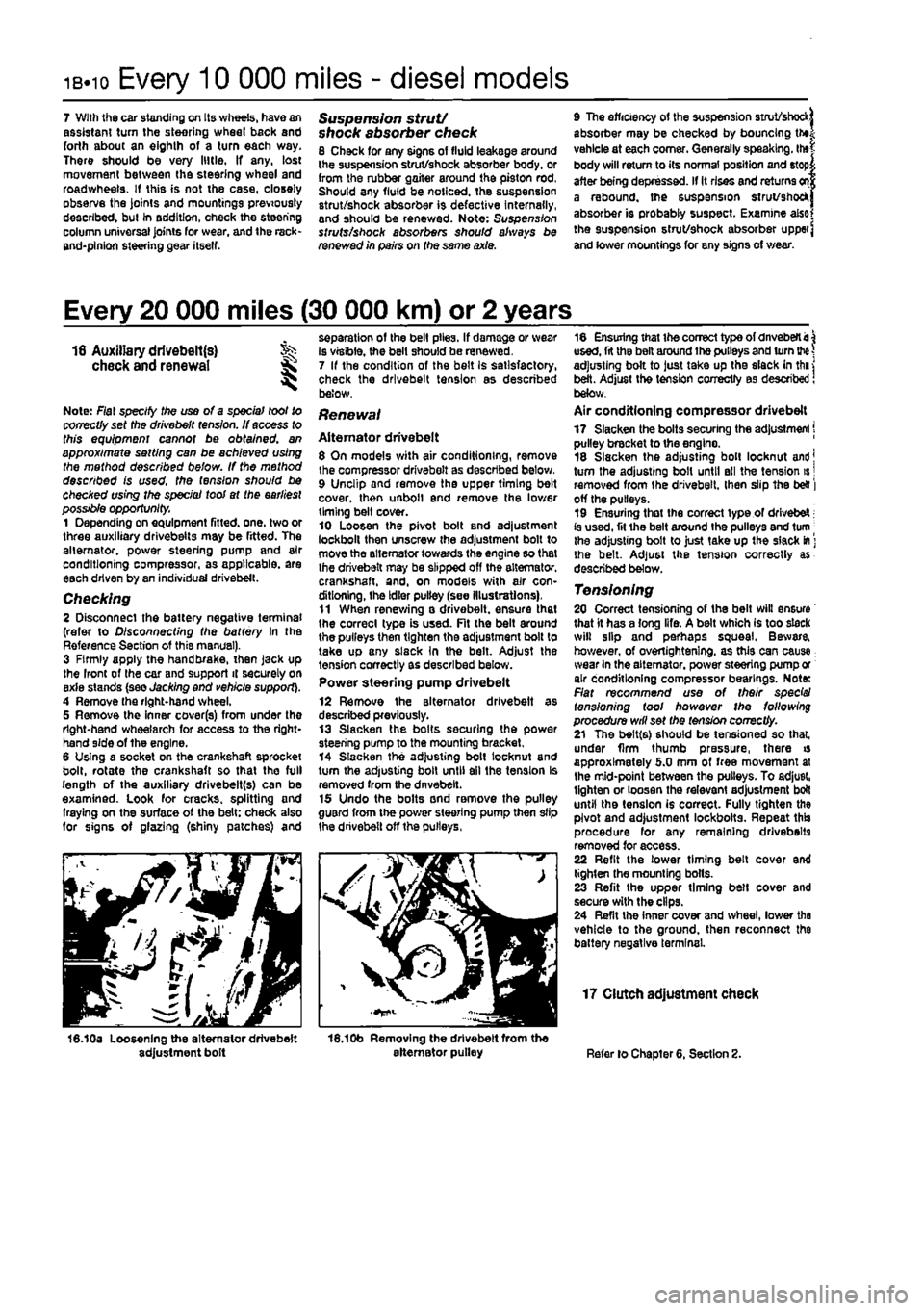
Alternator drivebelt 8 On models with air conditioning, remove the compressor drivebelt as described below, 9 Unclip and remove the upper timing belt cover, then unbolt end remove the lower timing belt cover. 10 Loosen the pivot bolt and adjustment lockbolt then unscrew the adjustment bolt to move the alternator towards the engine so that the drivebelt may be slipped off the alternator, crankshaft, and, on models with air con-ditioning, the Idler pulley (see Illustrations), 11 When renewing a drivebelt. ensure that the correct type is used. Fit the belt around the pulleys then tighten the adjustment bolt to take up any slsck In the belt. Adjust the tension correctly as described below. Power steering pump drivebelt
12 Remove the alternator drivebelt as described previously. 13 Slacken the bolts securing the power steering pump to the mounting bracket. 14 Slacken the adjusting bolt locknut and turn the adjusting bolt until ail the tension Is removed from the dnvebelt. 15 Undo the bolts and remove the pulley guard from the power steering pump then slip the drivebelt off the pulleys,
16.10b Removing the drivebelt from the alternator pulley
18 Ensuring that the correct type of dnveberti^ used, fit the belt around the pulleys and turn
the
adjusting bolt to just take up the slack in thi j belt. Adjust the tension correctly as described! below. Air conditioning compressor drivebelt 17 Slacken the bolts securing the adjustment j pulley bracket to the engine. 18 Slacken the adjusting bolt locknut and] turn the adjusting bolt until ell the tension is | removed from the drivebelt. then slip the be& | off the pulleys. 19 Ensuring that the correct type of drivebeX; is used, fit ihe belt around the pulleys and turn | the adjusting bolt to just take up the slack
m
] the belt. Adjust the tension correctly as described below.
Tensioning 20 Correct tensioning of the belt will ensure that it has a long life. A belt which is too slack will slip and perhaps squeal. Beware, however, of overiightenlng. as this can cause wear in the alternator, power steering pump or air conditioning compressor bearings. Note: Flat recommend use of their spec's/ tensioning tool however the following procedure will set the tension correctly. 21 The belt(s) should be tensioned so that, under firm thumb pressure, there is approximately 5.0 mm of free movement at the mid-point between the pulleys. To adjust, tighten or loosen the relevant adjustment bolt until the tension is correct. Fully tighten the pivot and adjustment lockbotts. Repeat this procedure for any remaining drivebeits removed for access. 22 Refit the lower timing belt cover end tighten the mounting bolts. 23 Refit the upper timing belt cover and secure with the clips. 24 Refit the inner cover and wheel, lower the vehicle to the ground, then reconnect the battery negative terminal.
17 Clutch adjustment check
Refer lo Chapter 6, Section 2.
Page 48 of 225
1B«12 Every 20 000 miles - diesel models
21 Road test
Instruments and electrical equipment 1 Check the operation of atl instruments and electrical equipment. 2 Make sure that all instruments read correctly, and switch on all electrical equipment rn turn, to check that It functions properly. Steering and suspension 3 Check for any abnormalities in the steering, suspension, handling or road feel. 4 Drive the vehicle, and check that there are no unusual vibrations or noises. 5 Check that the steering feete positive, with no excessive sloppiness, or roughness, and check for any suspension noises when cornering and driving over bumps. Drivetrain 6 Check (he performance of the engine, clutch, transmission and driveshafts.
7 Listen for any unusual noises from the engine, clutch and transmission. 8 Make sure that the engine runs smoothly when Idling, and that there is no hesitation when accelerating. 9 Check that the clutch action is smooth and progressive, that tho drive is taken up smoothly, and that the pedal travel Is not excessive. Also listen for any noises when the clutch pedal is depressed. 10 Check that all gears can be engaged smoothly without noise, and that the gear lever action Is not abnormally vague or notchy. 11 Listen for a metallic clicking sound from ihe front of the vehicle, as the vehicle « driven slowly In a circle with the steering on full-lock. Carry out this check In both directions, if a clicking noise is heard, this Indicates wear in a driveshaft |oinl, in which case renew the joint if necessary.
Check the braking system 12 Make sure that the vehicle does not pull to one side when braking, and that the wheels do not lock prematurely when braking hard.
13 Check that there Is no vibration through the steering when braking. 14 Check that the handbrake operates correctiy without excessive movement of th« lever, end that it holds the vehicle stationery on a slope. 15 Test the operation of the brake servo unit as follows. With the engine off, depress the footbrake four or five times to exhaust the vacuum. Hold the brake pedal depressed, then start the engine. As the engine starts, there should be a noticeable give In the brake pedal as vacuum builds up. Allow the engine to run for at least two minutes, and then switch it off. If the brake pedal is depressed now, it should be possible to detect a hiss from the servo es the pedal is depressed. After about four or five applications, no fimher hissing should be heard, and the pedal should feel considerably harder. Note: The vacuum for the servo unit is provided by the vacuum pump mounted on the left-hand end of t/ie cylinder head.
Every 30 000 miles (45 000 km) or 3 years
22 Manual transmission oil level check ;5§
1 Park the vehicle on a level surface. If possible over an inspection pit or on a ramp as the filler/level plug is best reached from under Ihe engine compartment. The oil level must be checked before the car Is driven, or at least 5 minutes after the engine has been switched off. If the oil is checked Immediately after driving the car. some of the oil will remain distnbuted around the transmission compo-nents, resulting In an inaccurate level reading. 2 Wipe clean the area around the filler/level plug, which is situated on tho front of the
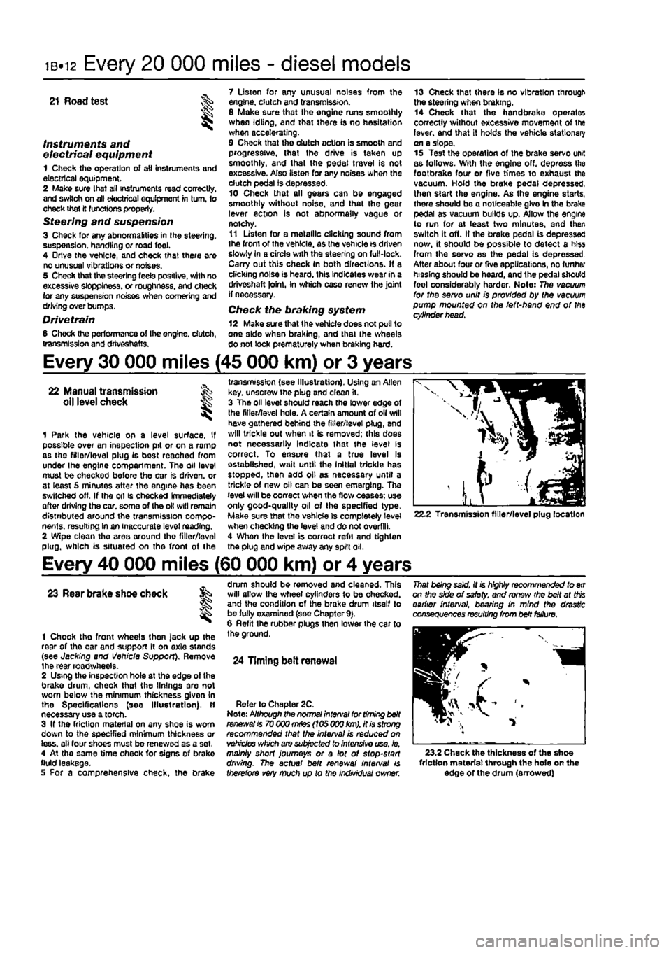
transmission (see illustration). Using an Allen key. unscrew the plug and clean it. 3 The oil level should reach the lower edge of the filler/level hole. A certain amount of oil will have gathered behind the filler/level plug, and will trickle out when it is removed; this does not necessarily Indicate that the level Is correct. To ensure that a true level Is established, wait until the Initial trickle has stopped, then add oil as necessary until a trickle of new oil can be seen emerging. The level will be correct when the flow ceases; use only good-quality oil of the specified type-Make sure that the vehicle Is completely level when checking the level and do not overfill. 4 When the level is correct refit and tighten the plug and wipe away any spilt oil.
22.2 Transmission filler/level plug location
Every 40 000 miles (60 000 km) or 4 years
23 Rear brake shoe check
1 Chock the front wheels then jack up the rear of the car and support It on axle stands (see Jacking and Vehicle Support), Remove the rear roadwhecla. 2 Using the inspection hole at the edge ot the brake drum, check that the linings are not worn below the minimum thickness given In the Spec ifi cat Ions (see Illustration). If necessary use a torch. 3 If the friction material on any shoe is worn down to the specified minimum thickness or iess. all four shoes must be renewed as a set, 4 At the same time check for signs of brake fluid leakage. 5 For a comprehensive check, the brake
drum should be removed and cleaned. This will allow the wheel cylinders to be checked, and the condition of the brake drum itself to be fully examined (see Chapter 9). 8 Refit the rubber plugs then lower the car to the ground.
24 Timing belt renewal
Refer to Chapter 2C. Note: Although the normal interval for timing belt
ranees/a!
is 70 000
mHes
(105 000
km),
it is strong recommended that the interval is reduced on vehicles which are subjected to intensive use, ie, mainly short journeys or a lot of stop-start driving. The actual belt renewal interval is therefore very much up to tho individual owner.
That being said, it is highly recommended to err on the side of safety, and renew (he belt at
this
earlier interval, bearing in mind the drastic consequences resulting from belt fetfure.
23.2 Check the thickness of the shoe friction material through the hole on the edge of the drum (arrowed)
Page 80 of 225
2C*2 Diesel engine in-car repair procedures
Refitting 6 Locate a new gasket on the cylinder head and make sure tt Is correctly seated. 7 Lower the cover onto the gasket making sure the gasket Is not displaced, 8 Insert the mounting bolts and tighten them securely In a progressive sequence. Position Ihe support brackets as noted during removal. 9 Clip ihe coolant hoses in position then refil the air ducting.
7 Camshaft oil seal -renewal
8 Crankshaft oil seals -renswal I
9 Cylinder head -
removal
and refitting
1 Remove the timing belt and camshaft sprocket as descnbed in Sections 4 and 5. 2 Using a suitable hooked instrument, remove tho oil seal from the cylinder head taking care nol to damage the surface of the camshafl. Alternatively drill a small hole In tho oil seal and Insert a self-topping screw - the seal can then be removed by pulling on the screw with a pair of pliers. 3 Clean the seating In the cylinder head and tho end of the camshaft To prevent damage to the new oil seal as It is being fitted, wrap some adhesive tape around the end ol the camshaft and lightJy oil it. 4 Dip tho new ail s«al In oil then locate it over Ihe camshaft making sure that the sealing lips are facing inwards. 5 Using a suitable tubular drift, drive the oil seal squarely into the cylinder h*ad. Remove the adhesive tap© 6 Refit the camshaft sprocket and timing belt with reference to Sections 6 and 4.
Front (right-hand side) oil seal t The front oil seal is located in the oil pump casing on the front of the crankshaft. Remove the timing belt as described in Section 4 and the crankshaft sprocket as described in Section 5, 2 Using a suitable hooked instrument, remove the oil seal from the oil pump casing taking care not to damage the surface of the crankshaft. Alternatively drill a small hole In the oil soal and insert a self-tapping screw - the seal can then be removed by pulling on the screw with a pair of pliers. 3 Clean the seating in the oH pump and the surface of the crankshaft. To prevent damage to the new off seal as It Is being fitted, wrap some adhesive tape around the end of tha crankshaft and lightly oil it. 4 Oip the new oii seal In oil then otter it up to the oil pump casing making sure that the sealing Hps are facing inwards,
8.Ba Rear oil soal and housing
5 Using a suitable tubular drift, driva the oil sea! squarely into the casing. Remove the adhesive tape. 6 Refit the crankshaft sprocket and timing belt with reference to Sections 5 and 4.
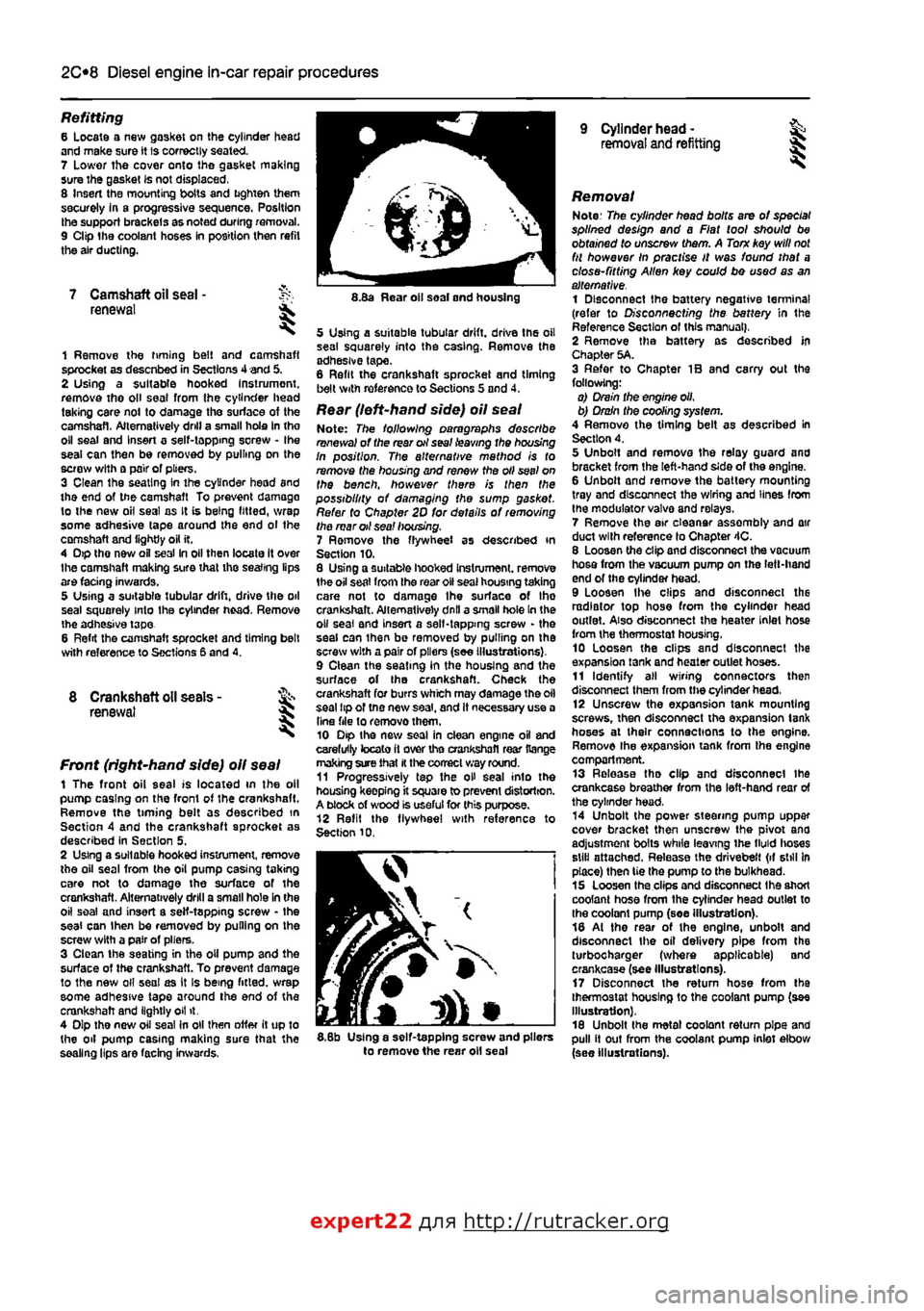
Rear (left-hand side) oil seal Note: The following paragraphs describe renewal of the rear oil seal leaving the housing In position. The alternative mathod is to remove the housing and renew the oil seel on the bench, however there is then the possibility of damaging the sump gasket. Refer to Chapter 2D for details of removing the mar oil sea! housing. 7 Ramove the flywheel as described in Section 10. 8 Using a suitable hooked Instrument. remove 1he oil seat from the roar oil seal housing taking care not to damage Ihe surface of Ihe crankshaft. Alternatively dnll a small hole In the o» seal and insert a self-tapping screw - the seal can ihan be removed by pulling on the screw with a pair of pliers (see Illustrations), 9 Clean the seating in the housing and the surface of the crankshaft. Check the crankshaft for burrs which may damage the oil seal tip of tno new saal, and It necessary use a Una file to removothem. 10 Dip the new soal in clean engine oil and carefully tocato it over tho crankshafl rear Range making sure that
H
the correct way round. 11 Progressively tap the oH seal into the housing keepfng it square to prevent distortion. A block of wood is useful for this purpose. 12 Refit the flywheel with reference to Section 10.
I
5.8b Using a self-tapping screw and pliers to remove the rear oil seal
Removal Note: The cylinder head bolts are of special splined design and a Fiat tool should be obtained to unscrew them. A Torn key will
not
fit however In practise It was found that a close-fitting Allen key could bo used as an alternative. 1 Disconnect the battery negative terminal (refer to Disconnecting the battery in the Reference Section of this manual), 2 Remove tha battery as described In Chapter 5A. 3 Refer to Chapter IB and carry out the following: o) Drain the engine oil, b) Drain the cooling system. 4 Remove the timing belt as described in Section 4. 5 Unbolt and remova the relay guard and bracket from the left-hand side of the engine. 6 Unbolt and remove the battery mounting tray and disconnect the wiring and lines from the modulator valva and relays. 7 Remove the air eleanar assembly and air duct with reference lo Chapter 4C. 8 Loosen the clip and disconnect the vacuum hosa from the vacuum pump on the left-hand end of the cylinder head. 9 Loosen Ihe clips and disconnect the radiator top hose from the cylinder head outlet. Also disconnect the heater inlet hose from the thermostat housing, 10 Loosen the clips and disconnect the expansion tank and heater outlet hoses. 11 Identify all wiring connectors then disconnect them from the cylinder head, 12 Unscrew the expansion tank mounting screws, then disconnect tha expansion tank hoses at their connections to the engine. Remove the expansion tank from tha engine compartment. 13 Release tha clip and disconnect ihe crankcase breather from the left-hand rear of the cylinder head. 14 Unbolt the power steering pump uppar cover bracket then unscrew the pivot ana adjustment bolts while leaving ihe tMd lioses still attached. Release the drivebelt (if still In place) then tie the pump to the bulkhead. 15 Loosen tha clips and disconnect Ihe short coolant hose from the cylinder head outlet to the coolant pump (soe illustration). 18 At the rear of the engine, unbolt and disconnect the oil delivery pipe from the turbocharger (where applicable) and crankcase (see Illustrations). 17 Disconnect the return hose from tha thermostat housing to the coolant pump (see Illustration), 18 Unbolt the metal coolant return pipe and pull it out from the coolant pump inlet elbow (see Illustrations).
expert22 flna http://rutracker.org
Page 92 of 225
2D*10 Engine removal and overhaul procedures
Engine and transmission -removal, separation, connection and refitting
Note: The engine Is lowered from the engine compartment as a complete unit with the transmission; tho two are then separated for overhaul.
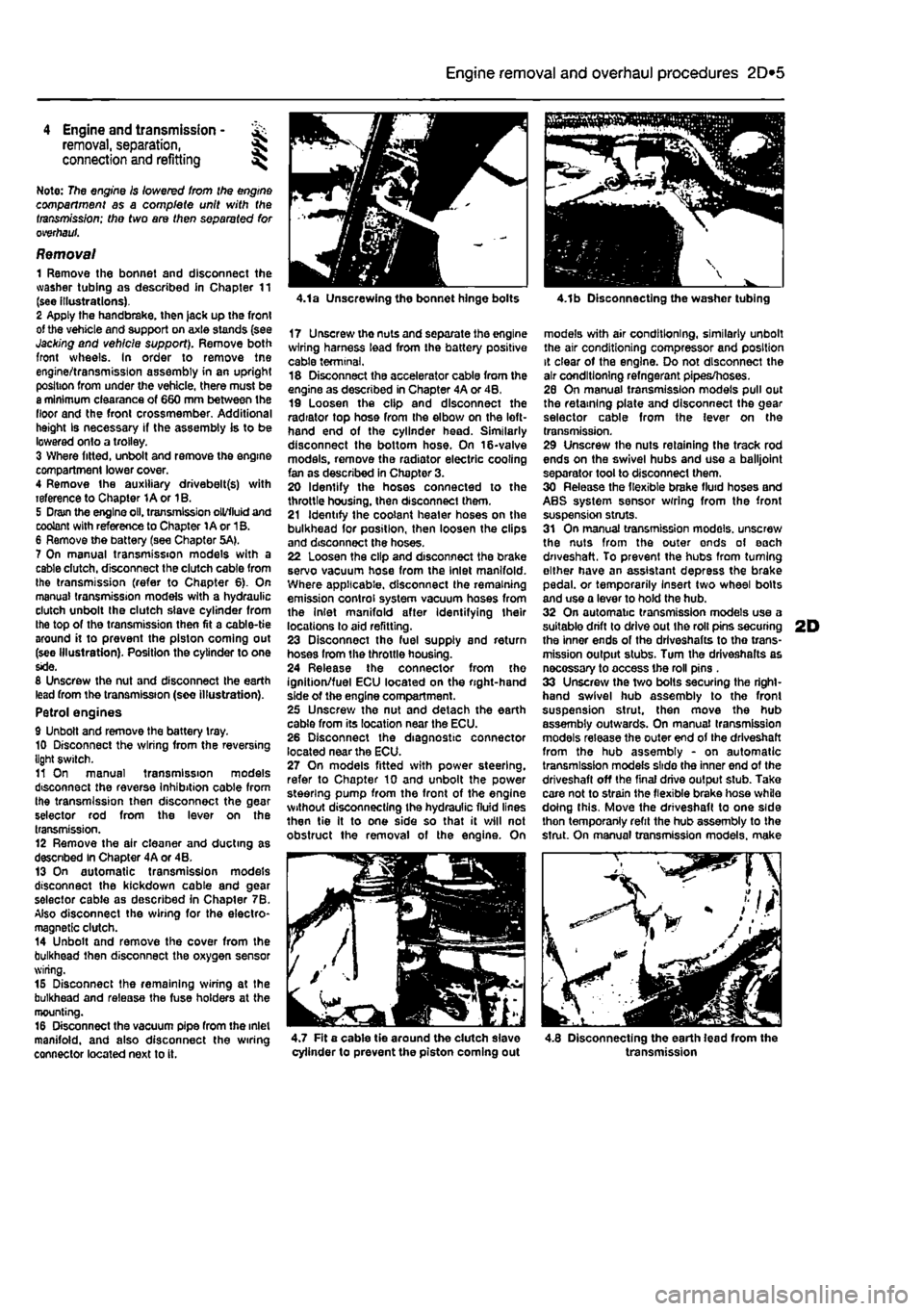
Removal 1 Remove the bonnet and disconnect the washer tubing as described in Chapter 11 (see illustrations). 2 Apply the handbrake, then jack up the front of the vehicle and support on axle stands (see Jacking and vehicle support). Remove both front wheels. In order to remove tne engine/transmission assembly in an upright position from under the vehicle, there must be a minimum clearance of 660 mm between the floor and the front crossmember. Additional height Is necessary if the assembly is to be lowered onto a trolley. 3 Where fitted, unbolt and remove the engine compartment lower cover. 4 Remove the auxiliary drivebelt(s) with reference to Chapter 1A or 1B. 5 Dram the engine oil. transmission oil/fluid and coolant with reference to Chapter 1A or 1B. 6 Remove the battery (see Chapter 5A). 7 On manual transmission models with a cable dutch, disconnect the clutch cable from the transmission (refer to Chapter 6). On manual transmission models with a hydraulic clutch unbolt the clutch slave cylinder from the top of the transmission then fit a cable-tie around it to prevent the piston coming out (see Illustration). Position the cylinder to one side. 8 Unscrew the nut and disconnect the earth lead from the transmission (see illustration). Petrol engines 9 Unbolt and remove the battery tray. 10 Disconnect the wiring from the reversing light switch. 11 On manual transmission models disconnect the reverse Inhibition cable from the transmission then disconnect the gear selector rod from the lever on the transmission. 12 Remove the air cleaner and ducting as descnbed In Chapter 4A or 4B. 13 On automatic transmission models disconnect the kickdown cable and gear selector cable as described in Chapter 7B. Also disconnect the wiring for the electro-magnetic clutch. 14 Unbolt and remove the cover from the bulkhead then disconnect the oxygen sensor wiring. 15 Disconnect the remaining wiring at the bulkhead and release the fuse holders at the mounting. 16 Disconnect the vacuum pipe from the inlet manifold, and also disconnect the wiring connector located next to it.
4.1a Unscrewing the bonnet hinge bolts
17 Unscrewthenutsandseparatetheengine wiring harness lead from the battery positive cable terminal. 18 Disconnect the accelerator cable from the engine as described in Chapter 4A or 4B, 19 Loosen the clip and disconnect the radiator top hose from the elbow on the left-hand end of the cylinder head. Similarly disconnect the bottom hose. On 16-valve models, remove the radiator electric cooling fan as described in Chapter 3. 20 Identify the hoses connected to the throttle housing, then disconnect them. 21 Identify the coolant heater hoses on the bulkhead for position, then loosen the clips and disconnect the hoses. 22 Loosen the clip and disconnect the brake servo vacuum hose from the Inlet manifold. Where applicable, disconnect the remaining emission control system vacuum hoses from the Inlet manifold after Identifying their locations to aid refitting. 23 Disconnect tho fuel supply and return hoses from the throttle housing. 24 Release the connector from the ignition/fuel ECU located on the right-hand side of the engine compartment. 25 Unscrew the nut and detach the earth cable from its location near the ECU. 26 Disconnect the diagnostic connector located near the ECU. 27 On models fitted with power steering, refer to Chapter 10 and unbolt the power steering pump from the front of the engine without disconnecting the hydraulic fluid lines then tie It to one side so that it will not obstruct the removal of the engine. On
4.1b Disconnecting the washer tubing
models with air conditioning, similarly unbolt the air conditioning compressor and position it clear of the engine. Do not disconnect the air conditioning refngerant pipes/hoses. 26 On manual transmission models pull out the retaining plate and disconnect the gear selector cable from the lever on the transmission. 29 Unscrew the nuts retaining the track rod ends on the swivel hubs and use a balljoint separator tool to disconnect them. 30 Release the flexible brake fluid hoses and ABS system sensor wrring from the front suspension struts. 31 On manual transmission models, unscrew the nuts from the outer ends of each driveshaft. To prevent the hubs from turning either have an assistant depress the brake pedal, or temporarily Insert two wheel bolts and use a lever to hold the hub. 32 On automatic transmission models use a suitable drift to drive out Ihe roll pins securing 2D the inner ends of the drlveshafts to tho trans-mission output stubs. Turn the driveshalts as necossary to access the roll pins . 33 Unscrew the two bolts securing the right-hand swivel hub assembly to the front suspension strut, then move the hub assembly outwards. On manual transmission models release the outer end of the driveshaft from the hub assembly - on automatic transmission models slide the inner end of the driveshaft off the final drive output stub. Take care not to strain the flexible brake hose while doing this. Move the driveshaft to one side thon temporanly refit the hub assembly to the strut. On manual transmission models, make
^ - / //
4.7 Fit a cable tie around the dutch slave cylinder to prevent the piston coming out 4.8 Disconnecting the earth lead from the transmission
Page 98 of 225
2D*10 Engine removal and overhaul procedures
05 Remove the brush holder assembly from the automatic transmission as described in Chapter 7B, Section 4. The brushes bear on the slip rings at the rear of the electro-magnetic clutch housing and they may be damaged when the transmission is removed. 86 Unscrew and remove the transmission-to-engine bolts then carefully draw the transmission away from the engine, resting It securely on wooden blocks. Collect the locating dowels If they are loose enough to be extracted, 87 If the oil pump driveshaft remains engaged with the crankshaft, remove it and reert Into the transmission to protect It from damage.
Connection 86 If the engine and transmission have not been separated, go to paragraph 104. Manual transmission models 89 Smear a little high-melting-point grease
on
the splines of the transmission input shaft. Do not use an excessive amount as there Is the risk of contaminating the clutch friction plate. 90 Carefully offer up the transmission to the engine cylinder block, guiding the input shaft through the clutch friction plate. 91 Refit the transmission-to-engine bolts and
the
single nut. hand^jghtenlng 1hem to secure the transmission in position. Note: Do not hghten them to force the engine and transmission together. Ensure that the beilhousing and cylinder block mating faces will butt together evenly without obstruction, before finally tightening the bolts and nut securely. Automatic transmission models 92 Check that the oil pump driveshaft is correctly engaged with the oil pump in the transmission. 93 Carefully offer up the transmission to Ihe rear of the engine and insert the oil pump driveshaft In the centre of the electro-magnetic clutch housing. Locate the transmission on the locating dowels then Insert the bolts and tighten them securely. 94 Refit the brush holder assembly to the automatic transmission with reference to Chapter 7B, Section 4. Petrol engines 96 Refit the transmission lower cover and tighten the bolts. 96 Locate the support bracket on the lower cover, then insert the bolts hand-tight. Also Insert the bolts securing the bracket lo the rear of Ihe cylinder block. With all the bolts Inserted, tighten them securely. 97 Refit the earth leads and tighten the bolts. Diesel engines 98 Refit the rpm sensor and tighten the bolts. 99 Insert the Intermediate shaft through the bracket then locate the dust boot on it and insert the Inner end in the transmission.
100 Refit and tighten the bolts securing the Intermediate shaft to the bracket on the rear of the cylinder block. 101 Refit the transmission lower cover and tighten the bolts. Ail models 102 Refit the starter motor (see Chapter 5A). 103 Refit the wiring harness to the components on the engine/transmission assembly making sure it is routed correctly.
Refitting 104 Locate the engine/transmission assembly beneath the engine compartment and attach the hoist to the lifting eyes. 105 Carefully lift the assembly up into the engine compartment taking care not to damage the surrounding components. 106 Reconnect the left-hand engine/trans-mission mounting to the body and tighten the bolts. 107 Reconnect Ihe right-hand engine mounting to the body and tighten the bolts. 108 Working beneath the vehicle, refit the rear engine mounting and tighten the bolts. 109 Disconnect the hoist from the engine and transmission lifting eyes and remove the hoist from under the vehicle. 110 The remainder of the refitting procedure is the direct reverse of the removal procedure, noting the following points:
a) Ensure that alf sections of the wiring harness follow their original routing; use new cable-ties to secure the harness In position, keeping it away from sources
of
heat and abrasion. b) On vehicles with manual transmission check and if necessary adjust the gearchenge cable and rod with reference to Chapter 7A. c) On vehicles with automatic transmission use new ro//p/ns fo secure the driveshafts to the transmission output stubs. Also check and if necessary adjust the kickdown end selector cables with reference to Chapter 78. d) Ensure that afi hoses are correctly routed and are secured with the correct hose clips, where applicable. If the hose clips cannot be used again; proprietary worm drive clips should be fitted
In
their place. e) Refill the cooling system as described in Chapter 1A or 18. f) Refill the engine with appropriate grades and quantities of oil (Chapter
1A
or 1B). g) Refit and adjust the auxiliary drivebelt(s) wfth reference fo Chapter 1A or 1B. h) Check and If necessary adjust the accelerator cable with reference to Chapter
AA,
48 or
AC.
i) When the engine is started for the first time, check for
air,
coolant, lubricant and fuel leaks from manifolds, hoses etc. If
the
engine has been overhauled, read
the
notes In Section 13 before attempting to starlit.
5 Engine overhaul • dismantling sequence
1 It is much easier to dismantle and work on the engine if it is mounted on a portable engine stand. These stands can often be hired from a tool hire shop. Before the engine is mounted on a stand, the flywheel should be removed, so that the stand bolts can be tightened Into the end of the cylinder block/crankcase. 2 If a stand Is not available, it Is possible to dismantle the engine with it blocked up on a sturdy workbench, or on the floor, Be very careful not to tip or drop the engine when working without a stand. 3 If you intend to obtain a reconditioned engine, all anclllarles must be removed first, to be transferred to the replacement engine (just as they will If you are doing a complete engine overhaul yourself). These components Include the following:
Petroi engines a) Power steering pump if removed with the engine (Chapter
10).
b) Alternator fmcluding mounting brackets) and starter motor (Chapter
SA).
c) The Ignition system and HT components including ail sensors, HT leads and
spark
plugs (Chapters 1A and
SB).
d) The fuel injection system components (Chapters A A and
AB).
e) All electrical switches, actuators and sensors, and the engine wiring harness (Chapters 4A, AB, SB). f) Inlet and exhaust manifolds (Chapters 4A, AB end
AD).
g) Engine oil dipstick and tube. h) Engine mountings (Chapter
2A).
i) Flywheef/driveptate (Chapter
2A).
j) Clutch components (Chapter
6)
- manual transmission. k) Electro-magnetic clutch components (Chapter 7B) - automatic transmission. I) Cooling system components (Chapter
3).
Diesei engines a) Power steering pump //removed with the engine (Chapter
10).
b) Alternator (Including mounting brackets) and starter motor (Chapter 5A). c) The glow plugfpre-heatlng system components (Chapter
SC).
d) Ait fuel system components, including the fuel injection pump, all sensors and actuators (Chapter
AC).
e) The vacuum pump. f) Ail electrical switches, actuators and sensors, and the engine wiring harness (Chapter 4C and 5C). g) Inlet and exhaust manifolds and, where applicable, the turbocharger (Chapter
AC
and 4D). h) The engine oil level dipstick and its tube. i) Engine mountings (Chapter
2C).
Page 158 of 225
6*1
Chapter 6
Clutch
Contents
Clutch - adjustment Clutch assembly - removal, inspection and refitting Clutch cable • removal and refitting Clutch hydraulic system - bleeding
Degrees of difficulty
2 Clutch master cylinder • removal and refitting 5 7 Clutch release mechanism - removal, Inspection and refitting 8 3 Clutch slave cylinder - removal and refitting 6 4 General information 1
Easy, suitable for
novice with little experience oi^
Faidy easy,
suitable for beginner
with
^
some
experience
Fairly difficult, suitable
for
competent ^
DIY
mechanic ^
Difficiit, suitable for ^ experienced DIY JR mechanic ^
V<*y difficult,
jk
suitable
for expert
DIY
« or professional ^
Specifications
General Type
Clutch pedal travel (cable-operated mechanism)
Friction plate diameter 8-valve petrol engines 16-valve petrol engines Diesel engines
Torque wrench setting Pressure plate retaining bolts
Single dry plate with diaphragm spring, cable- or hydraullcally-operated according to model 140.0 ± 5.0 mm
181.5 mm 190.0 mm 200.0 mm
Nm Ibf ft 16 12
1 General information
Vehicles with manual transmission are fitted with a pedal operated single dry plate clutch system. When the clutch pedal is depressed, effort is transmitted to the clutch release mechanism either mechanically by means of a cable, or hydraullcally by means of a master
2.5 Clutch cable adjustment
cylinder and slave cylinder. The release mechanism transfers effort to Ihe pressure plate diaphragm spring, which withdraws the pressure plate from the flywheel and releases the driven plate-Where applicable, the hydraulic fluid employed in the clutch system is the same as that used in the braking system, hence fluid is supplied to the master cylinder from a tapping on the brake fluid reservoir. The clutch hydraulic system must be sealed before work Is carried out on any of its components and then on completion, topped up and bled to remove any air bubbles.
2 Clutch - % adjustment §§ ^
Note: This procedure applies to models fitted with a cable-operated dutch
release
mechanism. No adjustment is possible on models with the hydrauHcaSy-operated system. 1 The clutch adjustment Is checked by measuring the clutch pedal travel. If a new cable has been fitted, settle it in position by depressing the clutch pedal at least thirty times. 2 Ensure that there are no obstructions
beneath the clutch pedal then measure the distance from the centre of the clutch pedal pad to the base of the steering wheel with the pedal In the at-rest position. Depress the clutch pedal fully to the floor, and measure the distance from the centre of the clutch pedal pad to the bata of the steering wheel. 3 Subtract the first measurement from the second to obtain the clutch pedal travel. If this is not with the range given in the Specifications at the start of this Chapter, adjust the clutch as follows. 4 The clutch cable Is adjusted by means of the adjuster nut on the transmission end of the cable. Access to the nut is from under the vehicle. Apply the handbrake then jack up the front of the vehicle and support on axle stands (see Jacking and vehicle support). 5 Working under the left-hand side of the engine compartment, slacken the locknut from the end of the clutch cable. Adjust the position of the adjuster nut. then depress the clutch pedal ten times and re-measure the dutch pedal travel. Repeat this procedure until the clutch pedal travel is as specified (see illustration). 6 Once the adjuster nut Is correctly positioned, and the pedal travel Is correctly set, securely tighten the cable locknut then lower the vehicle to the ground.