spark FIAT PUNTO 1999 176 / 1.G Owner's Guide
[x] Cancel search | Manufacturer: FIAT, Model Year: 1999, Model line: PUNTO, Model: FIAT PUNTO 1999 176 / 1.GPages: 225, PDF Size: 18.54 MB
Page 155 of 225

Ignition system - petrol models 5B®3
Chapter 1A tor further information. Also check tnat tha accelerator cable is correctly adjusted
as
described in the relevant part of Chapter 4. If the engine is running very roughly, check the compression pressures and the valve clearances as descnbed In the relevant parts of Chapters 1 and 2. 2
H
these checks fall to reveal the cause of the problem, the vehicle should be taken to a suitably equipped Fiat dealer for testing. A wiring block connector Is Incorporated in the engine management circuit Into which a special electronic diagnostic tester can be plugged. The tester will locate the fault quickly and simply alleviating the need to test all the system components Individually which is a time consuming operation that carries a high risk of damaging the ECU. 3 The only Ignition system checks which can
oe
earned out by the home mechanic are those cescribed in Chapter 1A, relating to the spark plugs, and the ignition coll test descnbed In this Chapter. If necessary, the system wiring and wiring connectors can oe checked as descnbed in Chapter 12, Section 2, ensuring that the ECU wiring connector(s) have first
been
disconnected.
3 Ignition HT coil - ^ removal, testing and refitting
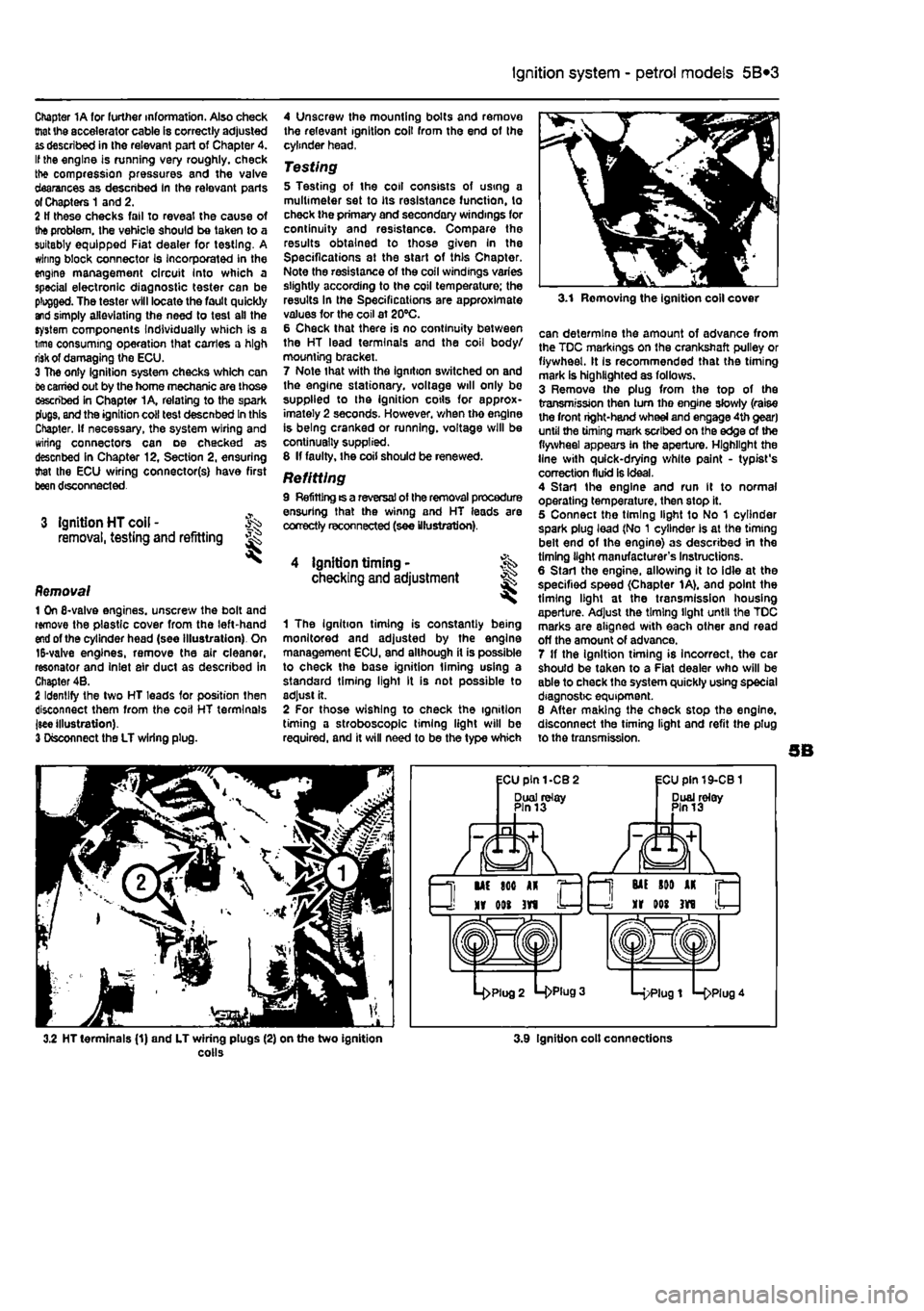
Removal 1 On 6-valve engines, unscrew the boll and remove the plastic cover from the left-hand
end
of the cylinder head (see Illustration). On 15-valve engines, remove the air cleaner, resonator and Inlet air duct as described in Chapter 4B. 2 Identify the two HT leads for position then disconnect them from the coil HT terminals jsee illustration). 3 Disconnect the LT wiring plug.
4 Unscrew the mounting bolts and remove the relevant ignition coil from the end of the cylinder head,
Testing 5 Testing of the coil consists of using a multimeter set to its resistance function, to check the primary and secondary windings for continuity and resistance. Compare the results obtained to those given In the Specifications at the start of this Chapter. Note the resistance of the coil windings varies slightly according to the coil temperature; the results In the Specifications are approximate values for the coil at 20°C. 6 Check that there is no continuity between the HT lead terminals and the coil body/ mourning bracket. 7 Note that with the ignition switched on and the engine stationary, voltage will only be supplied to the ignition cotls for approx-imately 2 seconds. However, when tho engine is being cranked or running, voltage will be continually supplied. 8 If faulty, the coil should be renewed.
Refitting 9 Refitting ts a reversal of the removal procedure ensuring that the winng and HT leads are correctly reconnected (see illustration).
4 ignition timing • checking and adjustment
1 The Ignition timing is constantly being monitored and adjusted by the engine management ECU, and although it is possible to check the base ignition liming using a standard timing light It is not possible to adjust it. 2 For those wishing to check the ignition timing a stroboscope timing light will be required, and it will need to be the type which
3.1 Removing the ignition coll cover
can determine the amount of advance from the TDC markings on the crankshaft pulley or flywheel. It Is recommended that the timing mark is highlighted as follows. 3 Remove the plug from the top of the transmission then turn tho engine slowly (raise the front right-hand wheel and engage 4th gear) until the timing mark scribed on the edge of the flywheel appears in the aperture. Highlight the line with quick-drying white paint - typist's correction fluid is ideal. 4 Start the engine and run It to normal operating temperature, then stop it. 5 Connect the timing light to No 1 cylinder spark plug lead (No 1 cylinder Is at the timing belt end of the engine) as described in the timing light manufacturer's Instructions. 6 Start the engine, allowing it to idle at the specified speed (Chapter 1A), and point the timing light at the transmission housing aperture. Adjust the timing light until the TDC marks are aligned with each other and read off the amount of advance. 7 If the ignition timing is incorrect, the car should be taken to a Fiat dealer who will be able to check the system quickly using special diagnostic equipment. 8 After making the check stop the engine, disconnect the timing light and refit the plug to the transmission.
3.2 HT terminals (1) and LT wiring plugs (2) on the two ignition colls 3.9 Ignition colt connections