ECU FIAT QUBO 2009 1.G Owners Manual
[x] Cancel search | Manufacturer: FIAT, Model Year: 2009, Model line: QUBO, Model: FIAT QUBO 2009 1.GPages: 202, PDF Size: 4.78 MB
Page 8 of 202
7
SAFETY
STARTING
AND DRIVING
WARNING
LIGHTS AND
MESSAGES
IN AN
EMERGENCY
MAINTENANCE
AND CARE
TECHNICAL
SPECIFICATIONS
INDEX
DASHBOARD
AND CONTROLS
THE FIAT CODE SYSTEM
This is an electrical engine locking system
which increases protection against at-
tempted theft of the vehicle. It is auto-
matically activated when the ignition key
is extracted.
Each time the vehicle is started turning the
ignition key to MAR, the Fiat CODE sys-
tem control unit sends a recognition code
to the engine control unit to deactivate
the inhibitor.
If, during ignition, the code is not correctly
recognized, a warning light Yis lit on the
instrument panel.
In this case, turn the key to STOPand
then back to MAR. Try with the other
keys provided if the problem persists. If
the engine will not start up after this op-
eration, run the emergency start proce-
dure (see chapter “In an emergency”) and
then contact the Fiat Dealership.
IMPORTANT Each key has its own code
which must be stored by the system ECU.
Contact the Fiat Dealership to have new
keys (up to eight) stored with the code.THE WARNING LIGHT
Y(or symbol on the display)
GOES ON DURING TRAVEL
❒If the warning light
Y(or symbol on the
display) turns on, the system is running
a self-test (for example for a voltage
drop). The first time you stop the vehi-
cle, turn the ignition key to STOPand
then to MAR. If no failure is detected,
the warning light
Ydoes not light up.
❒If the warning light
Y(or symbol on
the display) remains steadily lit, repeat
the procedure above leaving the key in
the STOPposition for over 30 sec-
onds. If the problem persists, contact
the Fiat Dealership.
❒If the warning light
Y(or symbol on
the display) stays on, the code is not ac-
knowledged. In this case, return the key
to STOPand then to MAR; try with
the other keys provided if the problem
persists. If the engine will not start up
after this operation, run the emergency
start procedure (see chapter “In an
emergency”) and then contact the Fiat
Dealership.
SYMBOLS
Special coloured labels have been attached
near or on some of the components of
your vehicle. These labels bear symbols
that draw your attention to the precau-
tions required when handling the compo-
nent in question.
The inner surface of the engine bonnet
includes a label with the different symbols
used.
The electronic components
inside the key may be dam-
aged if the key is subjected to
violent shocks.
001-035 QUBO GB 1ed:001-035 Fiorino GB 1ed 3-12-2009 15:58 Pagina 7
Page 36 of 202
35
SAFETY
STARTING
AND DRIVING
WARNING
LIGHTS AND
MESSAGES
IN AN
EMERGENCY
MAINTENANCE
AND CARE
TECHNICAL
SPECIFICATIONS
INDEX
DASHBOARD
AND CONTROLS
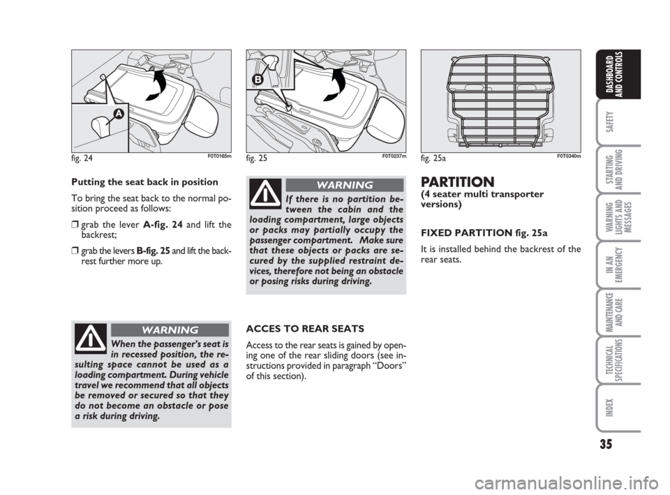
fig. 24F0T0165mfig. 25F0T0237m
Putting the seat back in position
To bring the seat back to the normal po-
sition proceed as follows:
❒grab the lever A-fig. 24and lift the
backrest;
❒grab the levers B-fig. 25and lift the back-
rest further more up.
When the passenger’s seat is
in recessed position, the re-
sulting space cannot be used as a
loading compartment. During vehicle
travel we recommend that all objects
be removed or secured so that they
do not become an obstacle or pose
a risk during driving.
WARNING
If there is no partition be-
tween the cabin and the
loading compartment, large objects
or packs may partially occupy the
passenger compartment. Make sure
that these objects or packs are se-
cured by the supplied restraint de-
vices, therefore not being an obstacle
or posing risks during driving.
WARNING
ACCES TO REAR SEATS
Access to the rear seats is gained by open-
ing one of the rear sliding doors (see in-
structions provided in paragraph “Doors”
of this section).
fig. 25aF0T0340m
PARTITION(4 seater multi transporter
versions)
FIXED PARTITION fig. 25a
It is installed behind the backrest of the
rear seats.
001-035 QUBO GB 1ed:001-035 Fiorino GB 1ed 3-12-2009 15:59 Pagina 35
Page 54 of 202
53
SAFETY
STARTING
AND DRIVING
WARNING
LIGHTS AND
MESSAGES
IN AN
EMERGENCY
MAINTENANCE
AND CARE
TECHNICAL
SPECIFICATIONS
INDEX
DASHBOARD
AND CONTROLS
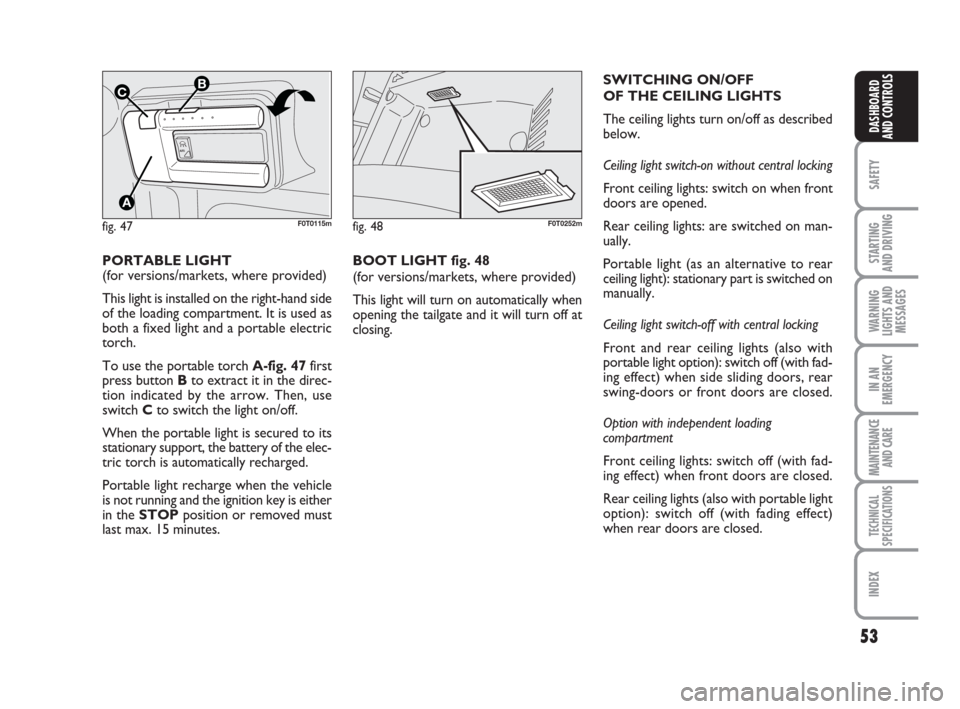
PORTABLE LIGHT
(for versions/markets, where provided)
This light is installed on the right-hand side
of the loading compartment. It is used as
both a fixed light and a portable electric
torch.
To use the portable torch A-fig. 47first
press button Bto extract it in the direc-
tion indicated by the arrow. Then, use
switch Cto switch the light on/off.
When the portable light is secured to its
stationary support, the battery of the elec-
tric torch is automatically recharged.
Portable light recharge when the vehicle
is not running and the ignition key is either
in the STOPposition or removed must
last max. 15 minutes.
fig. 47
A
UT
O
B
A
C
F0T0115mfig. 48F0T0252m
BOOT LIGHT fig. 48
(for versions/markets, where provided)
This light will turn on automatically when
opening the tailgate and it will turn off at
closing.SWITCHING ON/OFF
OF THE CEILING LIGHTS
The ceiling lights turn on/off as described
below.
Ceiling light switch-on without central locking
Front ceiling lights: switch on when front
doors are opened.
Rear ceiling lights: are switched on man-
ually.
Portable light (as an alternative to rear
ceiling light): stationary part is switched on
manually.
Ceiling light switch-off with central locking
Front and rear ceiling lights (also with
portable light option): switch off (with fad-
ing effect) when side sliding doors, rear
swing-doors or front doors are closed.
Option with independent loading
compartment
Front ceiling lights: switch off (with fad-
ing effect) when front doors are closed.
Rear ceiling lights (also with portable light
option): switch off (with fading effect)
when rear doors are closed.
036-082 QUBO GB 1ed:_ 3-12-2009 11:55 Pagina 53
Page 65 of 202

64
SAFETY
STARTING
AND DRIVING
WARNING
LIGHTS AND
MESSAGES
IN AN
EMERGENCY
MAINTENANCE
AND CARE
TECHNICAL
SPECIFICATIONS
INDEX
DASHBOARD
AND CONTROLS
BOOT
BOOT OPENING
FROM OUTSIDE
The tailgate (when unlocked) can only be
opened from outside using the powered
handle A-fig. 71located beneath the
shackle.
If doors are unlocked the boot can be
opened at any time.
To open it, one of the front doors shall be
opened or doors shall be unlocked using
the remote control or the key without re-
mote control.
fig. 71
A
F0T0250m
Never exceed the maximum
allowed load in the boot (see
section “Technical Specifications”).
Make sure that the objects are well
arranged in the boot so that they will
not be projected forwards following
sudden braking.
WARNING
If you travel in areas with
few filling stations and you
want to transport fuel in a spare tank,
respect applicable laws and exclu-
sively use a type-approved suitably
secured tank. However, the risks in
case of collision increase.
WARNING
fig. 72
A
F0T0285m
EMERGENCY OPENING
FROM INSIDE
In case of emergency the boot can be
opened from inside the vehicle as de-
scribed below.
❒Open the sliding side door and fold the
rear seats over completely;
❒working inside the luggage compart-
ment, press lever A-fig. 72and open
the tailgate.
036-082 QUBO GB 1ed:_ 3-12-2009 11:55 Pagina 64
Page 68 of 202
67
SAFETY
STARTING
AND DRIVING
WARNING
LIGHTS AND
MESSAGES
IN AN
EMERGENCY
MAINTENANCE
AND CARE
TECHNICAL
SPECIFICATIONS
INDEX
DASHBOARD
AND CONTROLS
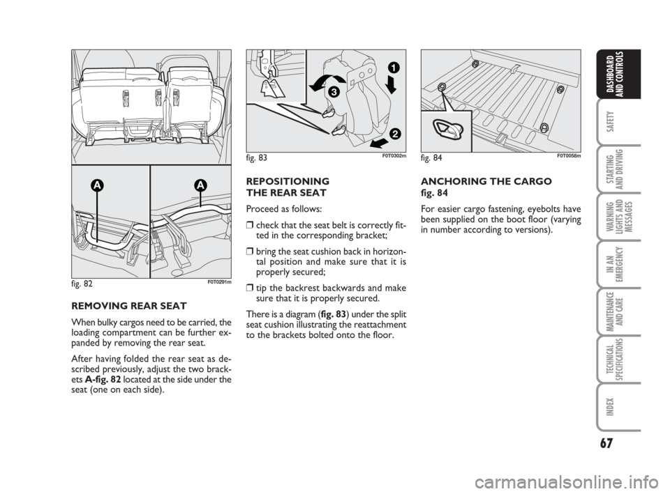
REMOVING REAR SEAT
When bulky cargos need to be carried, the
loading compartment can be further ex-
panded by removing the rear seat.
After having folded the rear seat as de-
scribed previously, adjust the two brack-
ets A-fig. 82located at the side under the
seat (one on each side).REPOSITIONING
THE REAR SEAT
Proceed as follows:
❒check that the seat belt is correctly fit-
ted in the corresponding bracket;
❒bring the seat cushion back in horizon-
tal position and make sure that it is
properly secured;
❒tip the backrest backwards and make
sure that it is properly secured.
There is a diagram (fig. 83) under the split
seat cushion illustrating the reattachment
to the brackets bolted onto the floor.
fig. 82
AA
F0T0291m
fig. 84F0T0058m
ANCHORING THE CARGO
fig. 84
For easier cargo fastening, eyebolts have
been supplied on the boot floor (varying
in number according to versions).
fig. 83
2
3
1
F0T0302m
036-082 QUBO GB 1ed:_ 3-12-2009 11:55 Pagina 67
Page 86 of 202
85
STARTING
AND DRIVING
WARNING
LIGHTS AND
MESSAGES
IN AN
EMERGENCY
MAINTENANCE
AND CARE
TECHNICAL
SPECIFICATIONS
INDEX
DASHBOARDAND CONTROLS
SAFETY
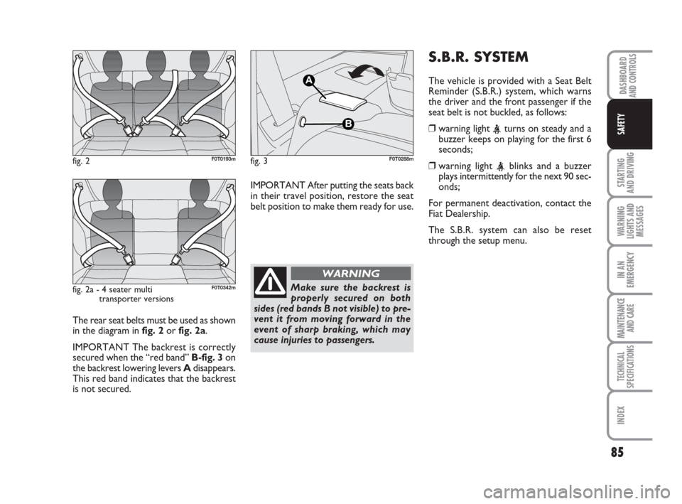
The rear seat belts must be used as shown
in the diagram in fig. 2 orfig. 2a.
IMPORTANT The backrest is correctly
secured when the “red band” B-fig. 3on
the backrest lowering levers Adisappears.
This red band indicates that the backrest
is not secured. IMPORTANT After putting the seats back
in their travel position, restore the seat
belt position to make them ready for use.
fig. 2F0T0193m
Make sure the backrest is
properly secured on both
sides (red bands B not visible) to pre-
vent it from moving forward in the
event of sharp braking, which may
cause injuries to passengers.
WARNING
fig. 3
A
B
F0T0288m
S.B.R. SYSTEM
The vehicle is provided with a Seat Belt
Reminder (S.B.R.) system, which warns
the driver and the front passenger if the
seat belt is not buckled, as follows:
❒warning light
seconds;
❒warning light
onds;
For permanent deactivation, contact the
Fiat Dealership.
The S.B.R. system can also be reset
through the setup menu.
fig. 2a - 4 seater multi
transporter versionsF0T0342m
083-100 QUBO GB 1ed:083-100 Fiorino GB 1ed 3-12-2009 11:58 Pagina 85
Page 90 of 202
89
STARTING
AND DRIVING
WARNING
LIGHTS AND
MESSAGES
IN AN
EMERGENCY
MAINTENANCE
AND CARE
TECHNICAL
SPECIFICATIONS
INDEX
DASHBOARDAND CONTROLS
SAFETY
CARRYING
CHILDREN SAFELY
For optimal protection in the event of a
crash, all passengers must be seated and
wear adequate restraint systems.
This is even more important for children.
This prescription is compulsory in all EC
countries according to EC Directive
2003/20/EC.
A child’s head is larger and heavier in pro-
portion to his/her body and the child’s
muscular and bone structures are not ful-
ly developed. For this reason, they require
restraint systems which are different from
those used by adults to protect them in
the event of an accident.The research results in relation to the best
protection for children is illustrated in Eu-
ropean standard CEE-R44 which divides
the restraint systems into five groups in
addition to making their use compulsory:
Group 0 up to 10 kg in weight
Group 0+ up to 13 kg in weight
Group 1 9-18 kg in weight
Group 2 15-25 kg in weight
Group 3 22-36 kg in weight
As it may be noted, the groups overlap
partly and, in fact, in commerce it is pos-
sible to find devices that cover more than
one weight group.All restraint devices must bear the type-
approval data along with the control mark
on a label that must be firmly secured to
the child seat and must never be removed.
Over 1.50 m in height, from the point of
view of restraint systems, children are
considered as adults and have to wear the
standard seat belts.
Lineaccessori Fiat includes child restraint
systems for each weight group. These de-
vices are recommended as they have been
specifically designed for Fiat cars/vehicles.
083-100 QUBO GB 1ed:083-100 Fiorino GB 1ed 3-12-2009 11:58 Pagina 89
Page 92 of 202
91
STARTING
AND DRIVING
WARNING
LIGHTS AND
MESSAGES
IN AN
EMERGENCY
MAINTENANCE
AND CARE
TECHNICAL
SPECIFICATIONS
INDEX
DASHBOARDAND CONTROLS
SAFETY
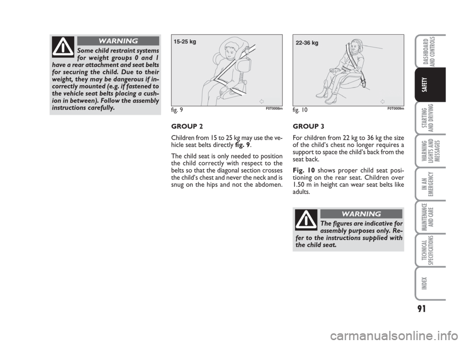
GROUP 2
Children from 15 to 25 kg may use the ve-
hicle seat belts directly fig. 9.
The child seat is only needed to position
the child correctly with respect to the
belts so that the diagonal section crosses
the child’s chest and never the neck and is
snug on the hips and not the abdomen.GROUP 3
For children from 22 kg to 36 kg the size
of the child’s chest no longer requires a
support to space the child’s back from the
seat back.
Fig. 10shows proper child seat posi-
tioning on the rear seat. Children over
1.50 m in height can wear seat belts like
adults.
fig. 9F0T0008mfig. 10F0T0009m
The figures are indicative for
assembly purposes only. Re-
fer to the instructions supplied with
the child seat.
WARNING
Some child restraint systems
for weight groups 0 and 1
have a rear attachment and seat belts
for securing the child. Due to their
weight, they may be dangerous if in-
correctly mounted (e.g. if fastened to
the vehicle seat belts placing a cush-
ion in between). Follow the assembly
instructions carefully.
WARNING
083-100 QUBO GB 1ed:083-100 Fiorino GB 1ed 3-12-2009 11:58 Pagina 91
Page 95 of 202
94
STARTING
AND DRIVING
WARNING
LIGHTS AND
MESSAGES
IN AN
EMERGENCY
MAINTENANCE
AND CARE
TECHNICAL
SPECIFICATIONS
INDEX
DASHBOARDAND CONTROLS
SAFETY
fig. 12F0T0145m
fig. 11F0T0010m
Fit the child seat when the
vehicle is stationary. The
child seat is correctly anchored to the
brackets when you hear the click. Fol-
low the instructions for assembly, dis-
assembly and positioning that the
manufacturer must supply with the
child seat.
WARNINGRemember that only Universal Isofix child
seats bearing the type-approval text “ECE
R44/03 Universal Isofix” can be used.
Universal Isofix “Duo Plus” child seat is
available from Lineaccessori Fiat.
For any further details regarding installa-
tion/use, refer to the “Instructions Man-
ual” that must be provided by the Manu-
facturer of the child restraint system.
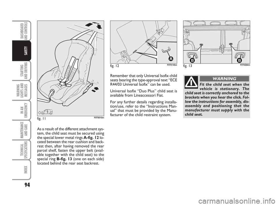
As a result of the different attachment sys-
tem, the child seat must be secured using
the special lower metal rings A-fig. 12lo-
cated between the rear cushion and back-
rest then, after having removed the rear
parcel shelf, fasten the upper belt (avail-
able together with the child seat) to the
special ring B-fig. 13(one on each side)
located behind the rear seat backrest.
fig. 13
BBF0T0284m
083-100 QUBO GB 1ed:083-100 Fiorino GB 1ed 3-12-2009 11:58 Pagina 94
Page 126 of 202
125
SAFETY
MAINTENANCE
AND CARE
TECHNICAL
SPECIFICATIONS
INDEX
DASHBOARDAND CONTROLS
STARTING
AND DRIVING
WARNING
LIGHTS AND
MESSAGES
IN AN
EMERGENCY
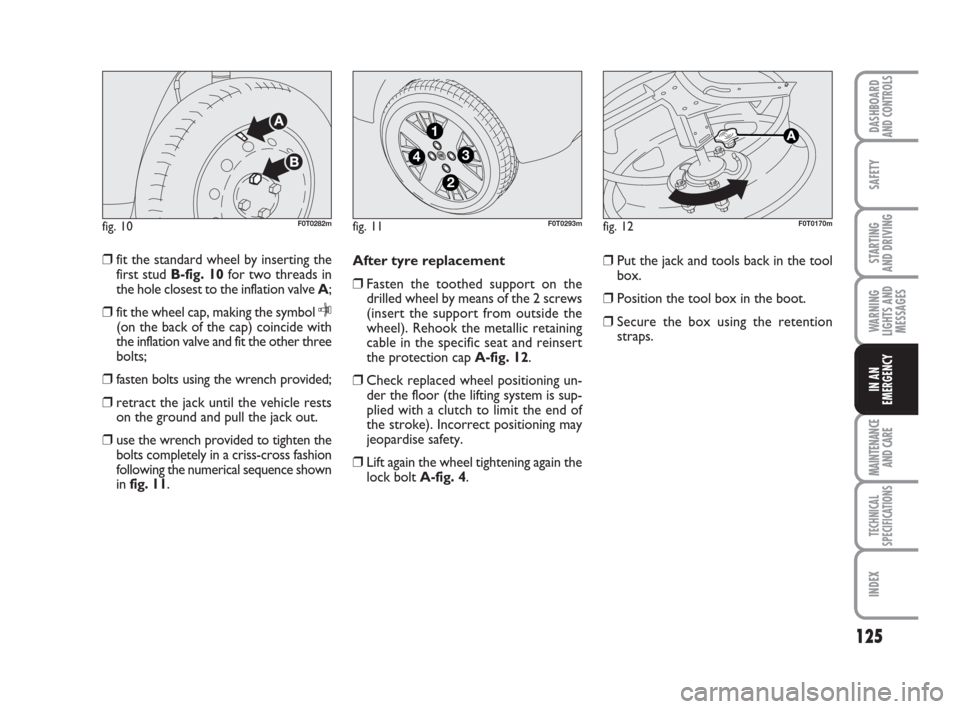
❒fit the standard wheel by inserting the
first stud B-fig. 10for two threads in
the hole closest to the inflation valve A;
❒fit the wheel cap, making the symbol
C(on the back of the cap) coincide with
the inflation valve and fit the other three
bolts;
❒fasten bolts using the wrench provided;
❒retract the jack until the vehicle rests
on the ground and pull the jack out.
❒use the wrench provided to tighten the
bolts completely in a criss-cross fashion
following the numerical sequence shown
in fig. 11.After tyre replacement
❒Fasten the toothed support on the
drilled wheel by means of the 2 screws
(insert the support from outside the
wheel). Rehook the metallic retaining
cable in the specific seat and reinsert
the protection cap A-fig. 12.
❒Check replaced wheel positioning un-
der the floor (the lifting system is sup-
plied with a clutch to limit the end of
the stroke). Incorrect positioning may
jeopardise safety.
❒Lift again the wheel tightening again the
lock boltA-fig. 4.❒Put the jack and tools back in the tool
box.
❒Position the tool box in the boot.
❒Secure the box using the retention
straps.
fig. 10F0T0282mfig. 11
4
1
3
2
F0T0293mfig. 12F0T0170m
119-150 QUBO GB 1ed:123-154 Fiorino GB 1ed 3-12-2009 16:00 Pagina 125