technical data FIAT QUBO 2017 1.G Repair Manual
[x] Cancel search | Manufacturer: FIAT, Model Year: 2017, Model line: QUBO, Model: FIAT QUBO 2017 1.GPages: 260, PDF Size: 4.74 MB
Page 66 of 260
To close the door, turn the key in the lock or press
the
button on the remote control.
WARNING
When closing, shut the right-hand door 2
fig. 66 fully before you close the
left-hand door 1 fig. 66. Never shut the two
doors at the same time.
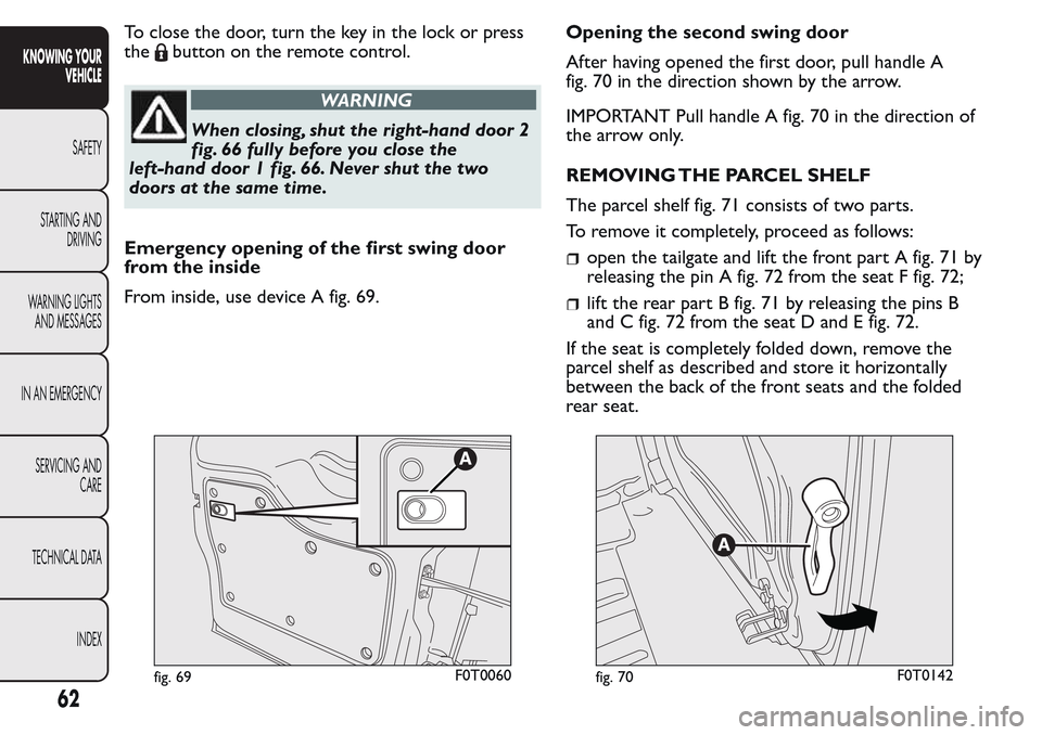
Emergency opening of the first swing door
from the inside
From inside, use device A fig. 69.Opening the second swing door
After having opened the first door, pull handle A
fig. 70 in the direction shown by the arrow.
IMPORTANT Pull handle A fig. 70 in the direction of
the arrow only.
REMOVING THE PARCEL SHELF
The parcel shelf fig. 71 consists of two parts.
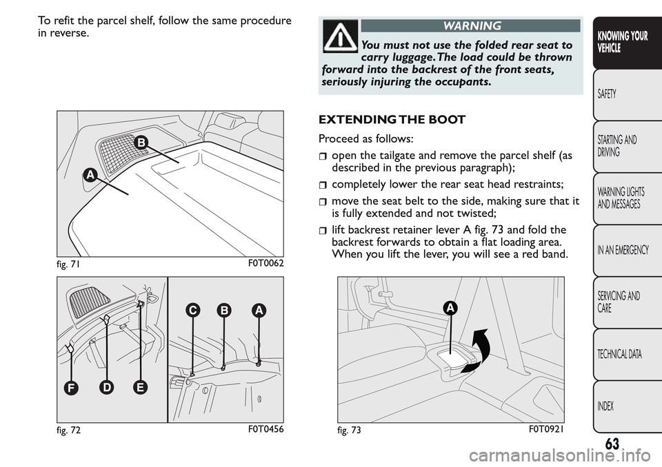
To remove it completely, proceed as follows:
open the tailgate and lift the front part A fig. 71 by
releasing the pin A fig. 72 from the seat F fig. 72;
lift the rear part B fig. 71 by releasing the pins B
and C fig. 72 from the seat D and E fig. 72.
If the seat is completely folded down, remove the
parcel shelf as described and store it horizontally
between the back of the front seats and the folded
rear seat.
fig. 69F0T0060fig. 70F0T0142
62
KNOWING YOUR
VEHICLE
SAFETY
STARTING AND
DRIVING
WARNING LIGHTS
AND MESSAGES
IN AN EMERGENCY
SERVICING AND
CARE
TECHNICAL DATA
INDEX
Page 67 of 260
To refit the parcel shelf, follow the same procedure
in reverse.WARNING
You must not use the folded rear seat to
carr y luggage.The load could be thrown
forward into the backrest of the front seats,
seriously injuring the occupants.
EXTENDING THE BOOT
Proceed as follows:
open the tailgate and remove the parcel shelf (as
described in the previous paragraph);
completely lower the rear seat head restraints;
move the seat belt to the side, making sure that it
is fully extended and not twisted;
lift backrest retainer lever A fig. 73 and fold the
backrest forwards to obtain a flat loading area.
When you lift the lever, you will see a red band.
fig. 71F0T0062
fig. 72F0T0456fig. 73F0T0921
63
KNOWING YOUR
VEHICLE
SAFETY
STARTING AND
DRIVING
WARNING LIGHTS
AND MESSAGES
IN AN EMERGENCY
SERVICING AND
CARE
TECHNICAL DATA
INDEX
Page 68 of 260
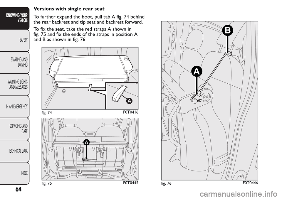
Versions with single rear seat
To further expand the boot, pull tab A fig. 74 behind
the rear backrest and tip seat and backrest forward.
To fix the seat, take the red straps A shown in
fig. 75 and fix the ends of the straps in position A
and B as shown in fig. 76
fig. 74F0T0416
A
fig. 75F0T0445
A
B
fig. 76F0T0446
64
KNOWING YOUR
VEHICLE
SAFETY
STARTING AND
DRIVING
WARNING LIGHTS
AND MESSAGES
IN AN EMERGENCY
SERVICING AND
CARE
TECHNICAL DATA
INDEX
Page 69 of 260
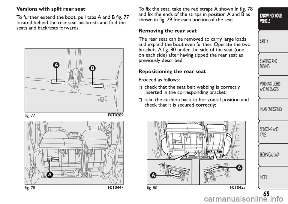
Versions with split rear seat
To further extend the boot, pull tabs A and B fig. 77
located behind the rear seat backrests and fold the
seats and backrests forwards.To fix the seat, take the red straps A shown in fig. 78
and fix the ends of the straps in position A and B as
shown in fig. 79 for each portion of the seat.
Removing the rear seat
The rear seat can be removed to carry large loads
and expand the boot even further. Operate the two
brackets A fig. 80 under the side of the seat (one
on each side) after having tipped the rear seat as
previously described.
Repositioning the rear seat
Proceed as follows:
check that the seat belt webbing is correctly
inserted in the corresponding bracket:
take the cushion back to horizontal position and
check that it is secured correctly;
fig. 77F0T0289
A
fig. 78F0T0447fig. 80F0T0455
65
KNOWING YOUR
VEHICLE
SAFETY
STARTING AND
DRIVING
WARNING LIGHTS
AND MESSAGES
IN AN EMERGENCY
SERVICING AND
CARE
TECHNICAL DATA
INDEX
Page 70 of 260
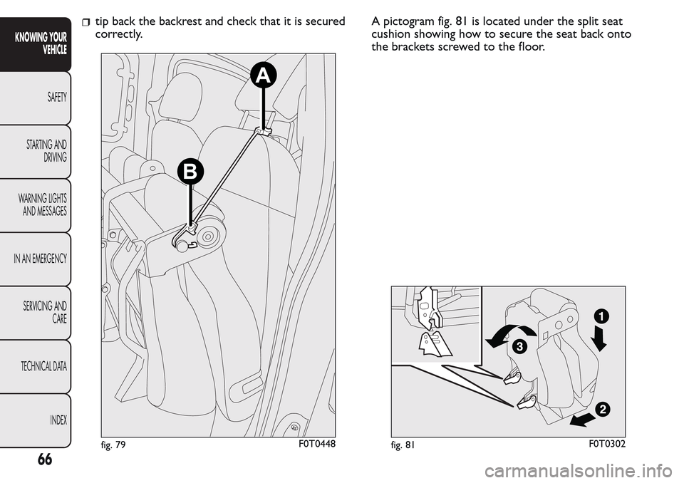
tip back the backrest and check that it is secured
correctly.A pictogram fig. 81 is located under the split seat
cushion showing how to secure the seat back onto
the brackets screwed to the floor.
B
A
fig. 79F0T0448fig. 81F0T0302
66
KNOWING YOUR
VEHICLE
SAFETY
STARTING AND
DRIVING
WARNING LIGHTS
AND MESSAGES
IN AN EMERGENCY
SERVICING AND
CARE
TECHNICAL DATA
INDEX
Page 71 of 260
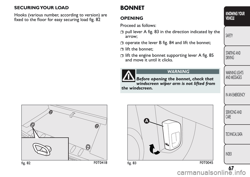
SECURING YOUR LOAD
Hooks (various number, according to version) are
fixed to the floor for easy securing load fig. 82BONNET
OPENING
Proceed as follows:
pull lever A fig. 83 in the direction indicated by the
arrow;
operate the lever B fig. 84 and lift the bonnet;
lift the bonnet;
lift the engine bonnet supporting lever A fig. 85
and move it until it clicks.
WARNING
Before opening the bonnet , check that
windscreen wiper arm is not lifted from
the windscreen.
fig. 82F0T0418fig. 83F0T0045
67
KNOWING YOUR
VEHICLE
SAFETY
STARTING AND
DRIVING
WARNING LIGHTS
AND MESSAGES
IN AN EMERGENCY
SERVICING AND
CARE
TECHNICAL DATA
INDEX
Page 72 of 260
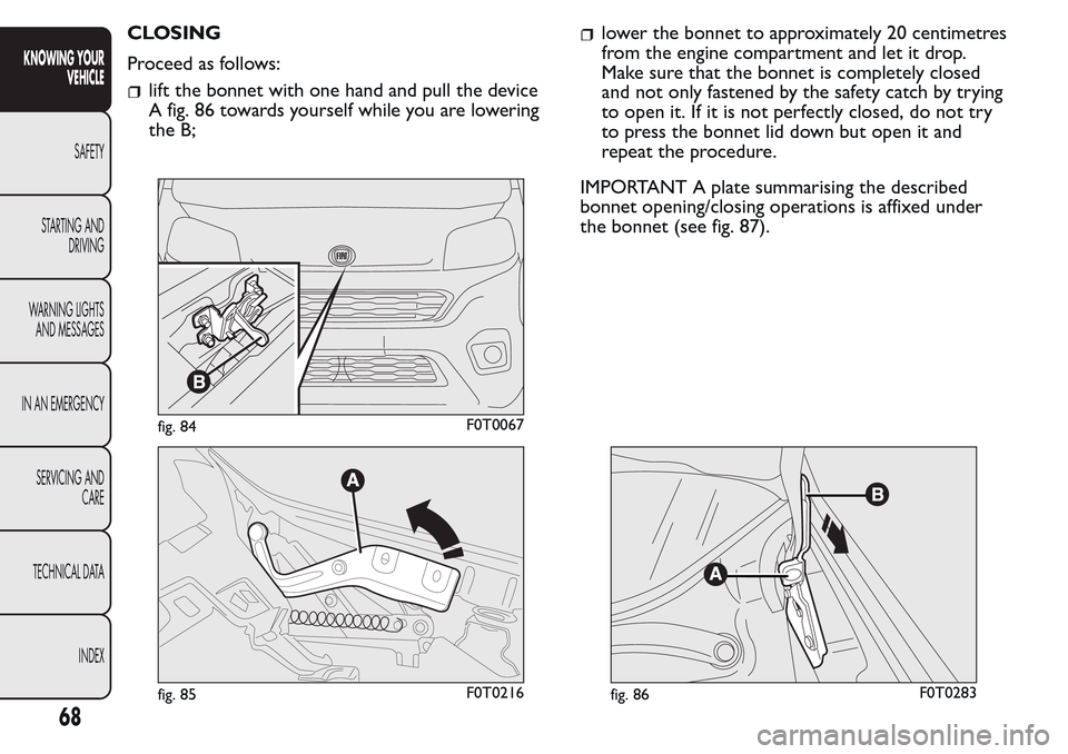
CLOSING
Proceed as follows:
lift the bonnet with one hand and pull the device
A fig. 86 towards yourself while you are lowering
the B;
lower the bonnet to approximately 20 centimetres
from the engine compartment and let it drop.
Make sure that the bonnet is completely closed
and not only fastened by the safety catch by trying
to open it. If it is not perfectly closed, do not try
to press the bonnet lid down but open it and
repeat the procedure.
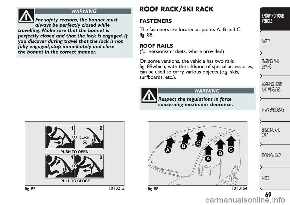
IMPORTANT A plate summarising the described
bonnet opening/closing operations is affixed under
the bonnet (see fig. 87).
fig. 84F0T0067
fig. 85F0T0216fig. 86F0T0283
68
KNOWING YOUR
VEHICLE
SAFETY
STARTING AND
DRIVING
WARNING LIGHTS
AND MESSAGES
IN AN EMERGENCY
SERVICING AND
CARE
TECHNICAL DATA
INDEX
Page 73 of 260
WARNING
For safety reasons, the bonnet must
always be perfectly closed while
travelling. Make sure that the bonnet is
perfectly closed and that the lock is engaged. If
you discover during travel that the lock is not
fully engaged, stop immediately and close
the bonnet in the correct manner.
ROOF RACK/SKI RACK
FASTENERS
The fasteners are located at points A, B and C
fig. 88.
ROOF RAILS
(for versions/markets, where provided)
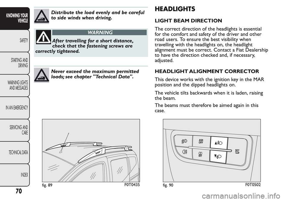
On some versions, the vehicle has two rails
fig. 89which, with the addition of special accessories,
can be used to carry various objects (e.g. skis,
surfboards, etc.).
WARNING
Respect the regulations in force
concerning maximum clearance.
fig. 87F0T0215fig. 88F0T0154
69
KNOWING YOUR
VEHICLE
SAFETY
STARTING AND
DRIVING
WARNING LIGHTS
AND MESSAGES
IN AN EMERGENCY
SERVICING AND
CARE
TECHNICAL DATA
INDEX
Page 74 of 260
Distribute the load evenly and be careful
to side winds when driving.
WARNING
After travelling for a short distance,
check that the fastening screws are
correctly tightened.
Never exceed the maximum permitted
loads; see chapter "Technical Data".
HEADLIGHTS
LIGHT BEAM DIRECTION
The correct direction of the headlights is essential
for the comfort and safety of the driver and other
road users. To ensure the best visibility when
travelling with the headlights on, the headlight
alignment must be correct. Contact a Fiat Dealership
to have the direction checked and, if necessary,
adjusted.
HEADLIGHT ALIGNMENT CORRECTOR
This device works with the ignition key in the MAR
position and the dipped headlights on.
The vehicle tilts backwards when it is laden, raising
the beam.
The beams must therefore be aimed again in this
case.
fig. 89F0T0435fig. 90F0T0502
70
KNOWING YOUR
VEHICLE
SAFETY
STARTING AND
DRIVING
WARNING LIGHTS
AND MESSAGES
IN AN EMERGENCY
SERVICING AND
CARE
TECHNICAL DATA
INDEX
Page 75 of 260
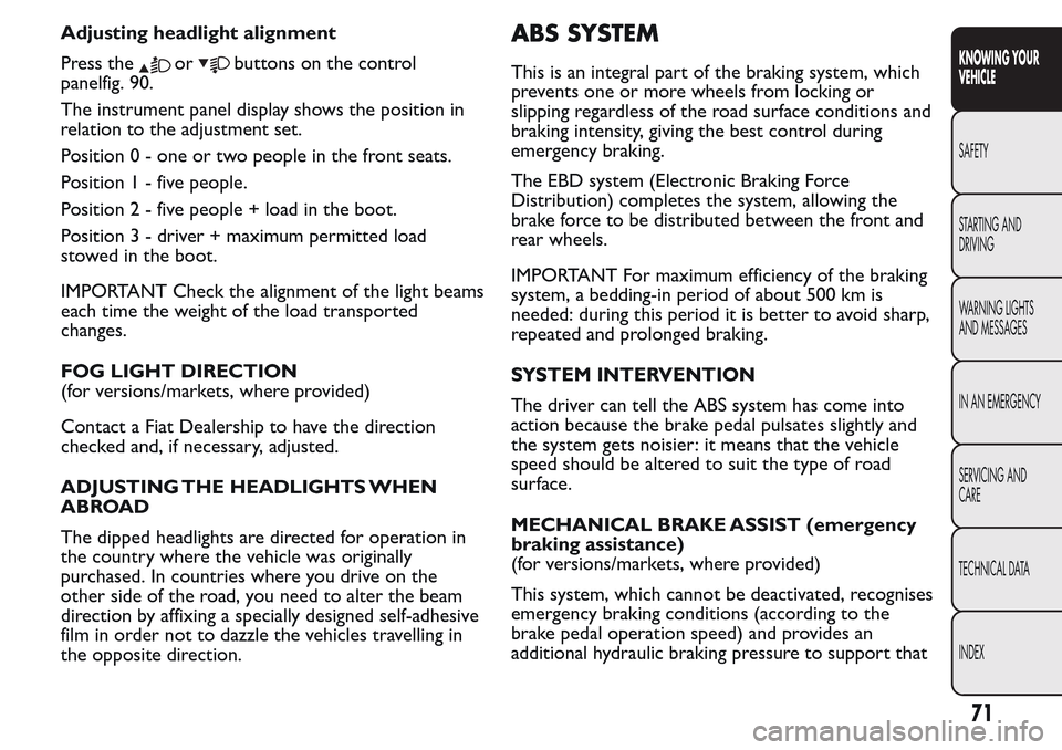
Adjusting headlight alignment
Press the
orbuttons on the control
panelfig. 90.
The instrument panel display shows the position in
relation to the adjustment set.
Position 0 - one or two people in the front seats.
Position1-fivepeople.
Position2-fivepeople + load in the boot.
Position 3 - driver + maximum permitted load
stowed in the boot.
IMPORTANT Check the alignment of the light beams
each time the weight of the load transported
changes.
FOG LIGHT DIRECTION
(for versions/markets, where provided)
Contact a Fiat Dealership to have the direction
checked and, if necessary, adjusted.
ADJUSTING THE HEADLIGHTS WHEN
ABROAD
The dipped headlights are directed for operation in
the country where the vehicle was originally
purchased. In countries where you drive on the
other side of the road, you need to alter the beam
direction by affixing a specially designed self-adhesive
film in order not to dazzle the vehicles travelling in
the opposite direction.
ABS SYSTEM
This is an integral part of the braking system, which
prevents one or more wheels from locking or
slipping regardless of the road surface conditions and
braking intensity, giving the best control during
emergency braking.
The EBD system (Electronic Braking Force
Distribution) completes the system, allowing the
brake force to be distributed between the front and
rear wheels.
IMPORTANT For maximum efficiency of the braking
system, a bedding-in period of about 500 km is
needed: during this period it is better to avoid sharp,
repeated and prolonged braking.
SYSTEM INTERVENTION
The driver can tell the ABS system has come into
action because the brake pedal pulsates slightly and
the system gets noisier: it means that the vehicle
speed should be altered to suit the type of road
surface.
MECHANICAL BRAKE ASSIST (emergency
braking assistance)
(for versions/markets, where provided)
This system, which cannot be deactivated, recognises
emergency braking conditions (according to the
brake pedal operation speed) and provides an
additional hydraulic braking pressure to support that
71
KNOWING YOUR
VEHICLE
SAFETY
STARTING AND
DRIVING
WARNING LIGHTS
AND MESSAGES
IN AN EMERGENCY
SERVICING AND
CARE
TECHNICAL DATA
INDEX