boot FIAT QUBO 2017 1.G Owners Manual
[x] Cancel search | Manufacturer: FIAT, Model Year: 2017, Model line: QUBO, Model: FIAT QUBO 2017 1.GPages: 260, PDF Size: 4.74 MB
Page 15 of 260
IMPORTANT The engine immobilizer function is
ensured by the Fiat CODE which is automatically
activated when the key is extracted from the ignition.
TURNING THE ALARM ON
With the doors and bonnet closed and the ignition
key either turned to STOP or removed, point the
key with the remote control towards the vehicle and
press and release button
.
Except for some markets, the system produces an
acoustic warning (beep) and enables door locking.
A self-diagnostic stage precedes the turning on of the
alarm: if a fault is detected, the system produces
another acoustic signal.
In this case switch off the alarm by pressing
,
check that all the doors, bonnet and tailgate are
closed correctly; then switch the alarm back on by
pressing
.
If a door or the bonnet is not properly shut, it will
be excluded from the testing by the alarm system.
A fault has occurred in system operation if the alarm
produces an acoustic signal even when the doors,
bonnet and boot are correctly closed. Go to a
Fiat Dealership.
IMPORTANT The alarm does not come on when the
central locking is activated using the metal insert in
the key.
IMPORTANT The alarm is configured to comply with
the regulations existing in different countries.TURNING THE ALARM OFF
Press button
on the key with the remote control.
The following operations are performed (excluding
specific markets):
direction indicators flash briefly twice
two short beeps
door are unlocked.
IMPORTANT The alarm is not turned off using the
door are opened using the metal insert in the key.
VOLUMETRIC/ANTILIFTING PROTECTION
The side windows must be completely closed for
correct operation of the protection.
If necessary, the function can be turned off (if, for
example, you are leaving a pet in the car) by pressing
button A fig. 7 on the front courtesy light before
activating turning the alarm on.
The LED on the button will flash for several seconds
when the function is turned off. The volumetric/
antitilting protection must be deactivated each time
the instrument panel is switched off.
BREAK-IN ATTEMPT INDICATION
The warning light
comes on or the symbol
appears on the display with a specific message (see
"Warning lights and messages" when the panel lights
up according to vehicle version) to indicate a
break-in attempt.
11
KNOWING YOUR
VEHICLE
SAFETY
STARTING AND
DRIVING
WARNING LIGHTS
AND MESSAGES
IN AN EMERGENCY
SERVICING AND
CARE
TECHNICAL DATA
INDEX
Page 64 of 260
The tailgate can be opened at any time if the doors
are unlocked.
To open it, enable the handle, opening one of the
front doors or unlocking the doors with the remote
control or using the key without remote control.
The tailgate unlocks also by pressing the
button
on the remote control.
To close the tailgate use handle B fig. 64.
Do not tr y to close the tailgate by
pressing on the side shock absorbers C
fig. 64. Also be careful not to knock the
side shock absorbers when you load the boot , to
avoid damaging them.
EMERGENCY OPENING FROM THE INSIDE
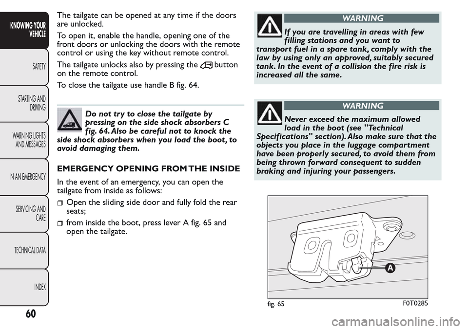
In the event of an emergency, you can open the
tailgate from inside as follows:
Open the sliding side door and fully fold the rear
seats;
from inside the boot, press lever A fig. 65 and
open the tailgate.
WARNING
If you are travelling in areas with few
filling stations and you want to
transport fuel in a spare tank, comply with the
law by using only an approved, suitably secured
tank. In the event of a collision the fire risk is
increased all the same.
WARNING
Never exceed the maximum allowed
load in the boot (see "Technical
Specifications" section). Also make sure that the
objects you place in the luggage compar tment
have been properly secured, to avoid them from
being thrown forward consequent to sudden
braking and injuring your passengers.
fig. 65F0T0285
60
KNOWING YOUR
VEHICLE
SAFETY
STARTING AND
DRIVING
WARNING LIGHTS
AND MESSAGES
IN AN EMERGENCY
SERVICING AND
CARE
TECHNICAL DATA
INDEX
Page 67 of 260
To refit the parcel shelf, follow the same procedure
in reverse.WARNING
You must not use the folded rear seat to
carr y luggage.The load could be thrown
forward into the backrest of the front seats,
seriously injuring the occupants.
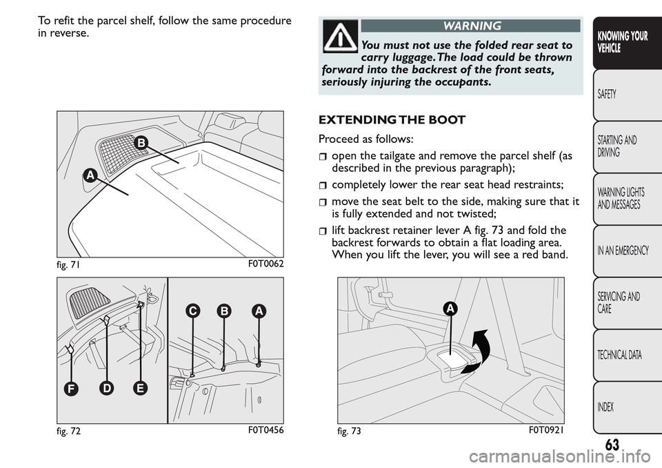
EXTENDING THE BOOT
Proceed as follows:
open the tailgate and remove the parcel shelf (as
described in the previous paragraph);
completely lower the rear seat head restraints;
move the seat belt to the side, making sure that it
is fully extended and not twisted;
lift backrest retainer lever A fig. 73 and fold the
backrest forwards to obtain a flat loading area.
When you lift the lever, you will see a red band.
fig. 71F0T0062
fig. 72F0T0456fig. 73F0T0921
63
KNOWING YOUR
VEHICLE
SAFETY
STARTING AND
DRIVING
WARNING LIGHTS
AND MESSAGES
IN AN EMERGENCY
SERVICING AND
CARE
TECHNICAL DATA
INDEX
Page 68 of 260
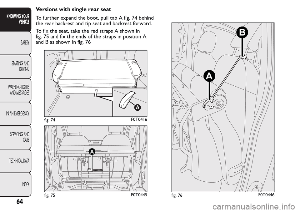
Versions with single rear seat
To further expand the boot, pull tab A fig. 74 behind
the rear backrest and tip seat and backrest forward.
To fix the seat, take the red straps A shown in
fig. 75 and fix the ends of the straps in position A
and B as shown in fig. 76
fig. 74F0T0416
A
fig. 75F0T0445
A
B
fig. 76F0T0446
64
KNOWING YOUR
VEHICLE
SAFETY
STARTING AND
DRIVING
WARNING LIGHTS
AND MESSAGES
IN AN EMERGENCY
SERVICING AND
CARE
TECHNICAL DATA
INDEX
Page 69 of 260
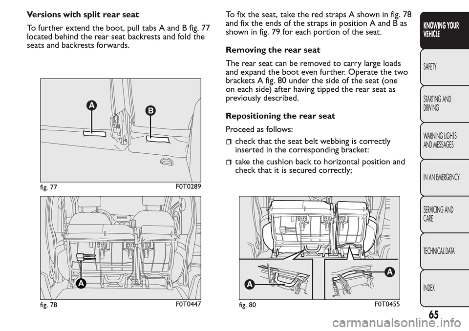
Versions with split rear seat
To further extend the boot, pull tabs A and B fig. 77
located behind the rear seat backrests and fold the
seats and backrests forwards.To fix the seat, take the red straps A shown in fig. 78
and fix the ends of the straps in position A and B as
shown in fig. 79 for each portion of the seat.
Removing the rear seat
The rear seat can be removed to carry large loads
and expand the boot even further. Operate the two
brackets A fig. 80 under the side of the seat (one
on each side) after having tipped the rear seat as
previously described.
Repositioning the rear seat
Proceed as follows:
check that the seat belt webbing is correctly
inserted in the corresponding bracket:
take the cushion back to horizontal position and
check that it is secured correctly;
fig. 77F0T0289
A
fig. 78F0T0447fig. 80F0T0455
65
KNOWING YOUR
VEHICLE
SAFETY
STARTING AND
DRIVING
WARNING LIGHTS
AND MESSAGES
IN AN EMERGENCY
SERVICING AND
CARE
TECHNICAL DATA
INDEX
Page 75 of 260
Adjusting headlight alignment
Press the
orbuttons on the control
panelfig. 90.
The instrument panel display shows the position in
relation to the adjustment set.
Position 0 - one or two people in the front seats.
Position1-fivepeople.
Position2-fivepeople + load in the boot.
Position 3 - driver + maximum permitted load
stowed in the boot.
IMPORTANT Check the alignment of the light beams
each time the weight of the load transported
changes.
FOG LIGHT DIRECTION
(for versions/markets, where provided)
Contact a Fiat Dealership to have the direction
checked and, if necessary, adjusted.
ADJUSTING THE HEADLIGHTS WHEN
ABROAD
The dipped headlights are directed for operation in
the country where the vehicle was originally
purchased. In countries where you drive on the
other side of the road, you need to alter the beam
direction by affixing a specially designed self-adhesive
film in order not to dazzle the vehicles travelling in
the opposite direction.
ABS SYSTEM
This is an integral part of the braking system, which
prevents one or more wheels from locking or
slipping regardless of the road surface conditions and
braking intensity, giving the best control during
emergency braking.
The EBD system (Electronic Braking Force
Distribution) completes the system, allowing the
brake force to be distributed between the front and
rear wheels.
IMPORTANT For maximum efficiency of the braking
system, a bedding-in period of about 500 km is
needed: during this period it is better to avoid sharp,
repeated and prolonged braking.
SYSTEM INTERVENTION
The driver can tell the ABS system has come into
action because the brake pedal pulsates slightly and
the system gets noisier: it means that the vehicle
speed should be altered to suit the type of road
surface.
MECHANICAL BRAKE ASSIST (emergency
braking assistance)
(for versions/markets, where provided)
This system, which cannot be deactivated, recognises
emergency braking conditions (according to the
brake pedal operation speed) and provides an
additional hydraulic braking pressure to support that
71
KNOWING YOUR
VEHICLE
SAFETY
STARTING AND
DRIVING
WARNING LIGHTS
AND MESSAGES
IN AN EMERGENCY
SERVICING AND
CARE
TECHNICAL DATA
INDEX
Page 132 of 260
SAVING FUEL
Some useful tips are given below for fuel saving and
reducing harmful emissions of CO2 and other
pollutants (nitrogen oxides, unburnt hydrocarbons,
Particulate Matter (PM) etc.).
GENERAL CONSIDERATIONS
The general factors that affect fuel consumption are
listed below.
Vehicle maintenance
Have checks and adjustments carried out in
accordance with the “Scheduled Servicing Plan”.
Ty r e s
Check the tyre pressure at least once every four
weeks: if the pressure is too low, consumption levels
increase as resistance to rolling is higher.
Unnecessary loads
Do not travel with an overloaded boot. The weight
of the vehicle (especially when driving in town)
and its trim greatly affect fuel consumption
and stability.
Roof rack/ski rack
Remove the roof rack or the ski rack from the roof
after use. These accessories reduce the aerodynamic
coefficient of the vehicle and have a negative effecton fuel consumption. It is better to use a trailer to
transport particularly bulky objects.
Electric devices
Only use electrical devices for the amount of time
needed. The heated rear window, additional
headlights, windscreen/rear window wipers and
heater fan need a considerable amount of energy,
therefore increasing fuel consumption (by up to 25%
in the urban cycle).
Climate control system
The air conditioner leads to higher fuel consumption
(on average up to +20%). If the temperature outside
is not too extreme, try and use the air vents.
Spoilers
The use of non-certified spoilers may adversely affect
aerodynamics and fuel consumption.
128
KNOWING YOUR
VEHICLE
SAFETY
STARTING AND
DRIVING
WARNING LIGHTS
AND MESSAGES
IN AN EMERGENCY
SERVICING AND
CARE
TECHNICAL DATA
INDEX
Page 142 of 260
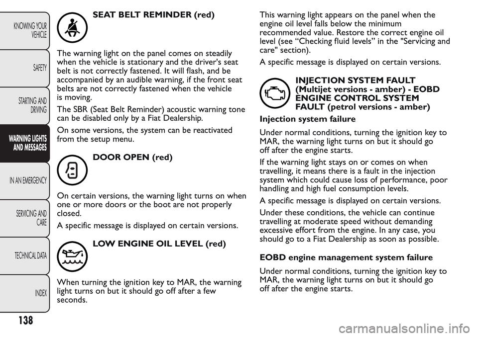
SEAT BELT REMINDER (red)
The warning light on the panel comes on steadily
when the vehicle is stationary and the driver's seat
belt is not correctly fastened. It will flash, and be
accompanied by an audible warning, if the front seat
belts are not correctly fastened when the vehicle
is moving.
The SBR (Seat Belt Reminder) acoustic warning tone
can be disabled only by a Fiat Dealership.
On some versions, the system can be reactivated
from the setup menu.
DOOR OPEN (red)
On certain versions, the warning light turns on when
one or more doors or the boot are not properly
closed.
A specific message is displayed on certain versions.
LOW ENGINE OIL LEVEL (red)
When turning the ignition key to MAR, the warning
light turns on but it should go off after a few
seconds.This warning light appears on the panel when the
engine oil level falls below the minimum
recommended value. Restore the correct engine oil
level (see “Checking fluid levels” in the "Servicing and
care" section).
A specific message is displayed on certain versions.
INJECTION SYSTEM FAULT
(Multijet versions - amber) - EOBD
ENGINE CONTROL SYSTEM
FAULT (petrol versions - amber)
Injection system failure
Under normal conditions, turning the ignition key to
MAR, the warning light turns on but it should go
off after the engine starts.
If the warning light stays on or comes on when
travelling, it means there is a fault in the injection
system which could cause loss of performance, poor
handling and high fuel consumption levels.
A specific message is displayed on certain versions.
Under these conditions, the vehicle can continue
travelling at moderate speed without demanding
excessive effort from the engine. In any case, you
should go to a Fiat Dealership as soon as possible.
EOBD engine management system failure
Under normal conditions, turning the ignition key to
MAR, the warning light turns on but it should go
off after the engine starts.
138
KNOWING YOUR
VEHICLE
SAFETY
STARTING AND
DRIVING
WARNING LIGHTS
AND MESSAGES
IN AN EMERGENCY
SERVICING AND
CARE
TECHNICAL DATA
INDEX
Page 153 of 260
indicate that the vehicle has broken down using
the devices required by the law in the current
country (e.g. warning triangle, hazard lights, etc.);
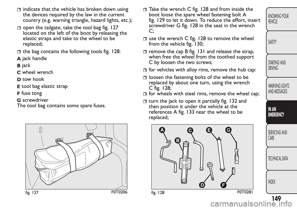
open the tailgate, take the tool bag fig. 127
located on the left of the boot by releasing the
elastic straps and take to the wheel to be
replaced;
the bag contains the following tools fig. 128:
Ajack handle
Bjack
Cwheel wrench
Dtow hook
Etool bag elastic strap
Ffuse tong
Gscrewdriver
The tool bag contains some spare fuses.
Take the wrench C fig. 128 and from inside the
boot loose the spare wheel fastening bolt A
fig. 129 to let it down. To reduce the effort, insert
screwdriver G fig. 128 in the seat in the wrench
C;
use the wrench C fig. 128 to remove the wheel
from the vehicle fig. 130;
remove the cap B fig. 131 and release the strap,
when free the wheel from the toothed support
C by loosen the two screws;
for vehicles with alloy rims, remove the hub cap:
loosen the fastening bolts of the wheel to be
replaced by about one turn, using the wrench
C fig. 128;
for wheels with steel rims, remove the wheel cap;
turn the jack to open it partially fig. 132 and
then position it under the vehicle at the
references A fig. 133 near the wheel to be
replaced;
fig. 127F0T0206fig. 128F0T0281
149
KNOWING YOUR
VEHICLE
SAFETY
STARTING AND
DRIVING
WARNING LIGHTS
AND MESSAGES
IN AN
EMERGENCY
SERVICING AND
CARE
TECHNICAL DATA
INDEX
Page 156 of 260
tighten the bolts using the spanner provided;
for vehicles with alloy rim, fit the hub cap;
turn the jack handle to lower the vehicle, and
remove the jack;
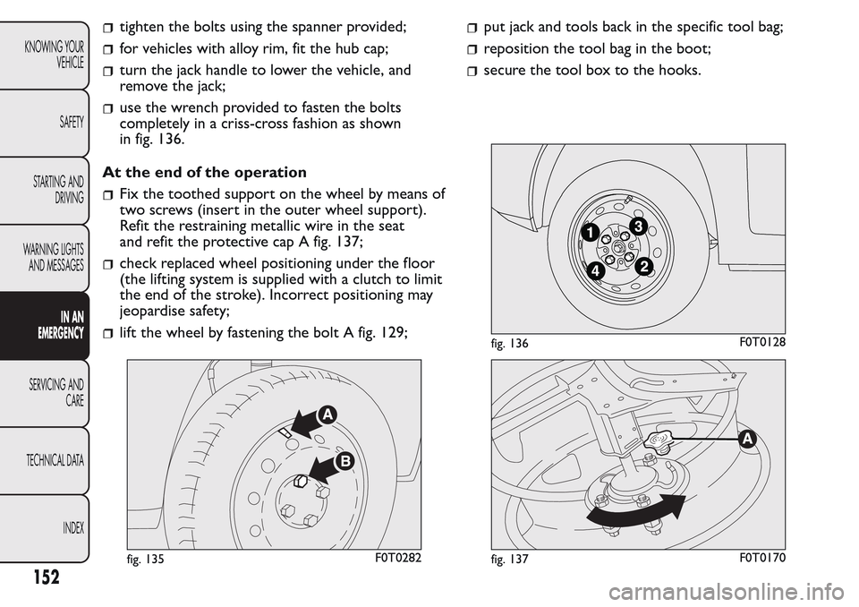
use the wrench provided to fasten the bolts
completely in a criss-cross fashion as shown
in fig. 136.
At the end of the operation
Fix the toothed support on the wheel by means of
two screws (insert in the outer wheel support).
Refit the restraining metallic wire in the seat
and refit the protective cap A fig. 137;
check replaced wheel positioning under the floor
(the lifting system is supplied with a clutch to limit
the end of the stroke). Incorrect positioning may
jeopardise safety;
lift the wheel by fastening the bolt A fig. 129;
put jack and tools back in the specific tool bag;
reposition the tool bag in the boot;
secure the tool box to the hooks.
fig. 135F0T0282
fig. 136F0T0128
fig. 137F0T0170
152
KNOWING YOUR
VEHICLE
SAFETY
STARTING AND
DRIVING
WARNING LIGHTS
AND MESSAGES
IN AN
EMERGENCY
SERVICING AND
CARE
TECHNICAL DATA
INDEX