display FIAT SCUDO 2010 Owner handbook (in English)
[x] Cancel search | Manufacturer: FIAT, Model Year: 2010, Model line: SCUDO, Model: FIAT SCUDO 2010Pages: 210, PDF Size: 3.32 MB
Page 45 of 210

44
SAFETY
DEVICES
CORRECT USE
OF THE
VEHICLE
WARNING
LIGHTS AND
MESSAGES
IN AN
EMERGENCY
VEHICLE
MAINTENANCE
TECHNICAL
SPECIFICATIONS
INDEX
DASHBOARD
AND
CONTROLS
Switching the climate control
system off (A/C) A
Press button Ato turn the system off.
When turned off the system conditions
are the following:
❒set temperature displays off;
❒air recirculation is on;
❒conditioner compressor off;
❒fan off.
Heated rear window can be turned on or
off also when the system is off.
IMPORTANT The system will store the
temperatures set before turning off and
will resume them when pressing any but-
ton (except heated rear window); if the
function corresponding to the button
pressed is off it will be turned on; if on it
will be kept active.
Press AUTOto turn the system in au-
tomatic mode.ADDITIONAL HEATER
(where provided)
This device shall be used to speed up pas-
senger compartment warming when it is
very cold.
The additional heater turns off automati-
cally after reaching the required comfort
conditions.
Automatic two-zone climate
control system
The additional heater will switch on au-
tomatically after turning the ignition key
to MAR.Manual Heater and Climate
control system
The additional heater will switch on au-
tomatically by turning knob M or Ito the
last red sector and turning the fan on
(knob D) to the first speed at least.
IMPORTANT Heater works only with
low outside temperature and engine
coolant temperature.
IMPORTANT Heater will not turn on if
the battery voltage is not sufficient.
Page 50 of 210
49
SAFETY
DEVICES
CORRECT USE
OF THE
VEHICLE
WARNING
LIGHTS AND
MESSAGES
IN AN
EMERGENCY
VEHICLE
MAINTENANCE
TECHNICAL
SPECIFICATIONS
INDEX
DASHBOARD
AND CONTROLS
Follow me home (where provided)
This function allows the illumination of the
space in front of the vehicle for a preset
period of time (45 seconds). To activate
it the ignition key shall be at Sor removed
and the left stalk shall be pushed towards
the dashboard within 2 minutes from
when the engine is turned off.
If the vehicle is fitted with automatic de-
vice for turning on side lights and dipped
beams, the follow me home function will
activate automatically when opening the
doors.AUTOMATIC HEADLIGHTS
SENSOR (daylight sensor)
(where provided)
It detects the changes of the external light
intensity of the vehicle according to the
light sensitivity set: the greater the sensi-
tivity is, the smaller the amount of exter-
nal light necessary to control the switch-
ing-on of the external headlights will be.
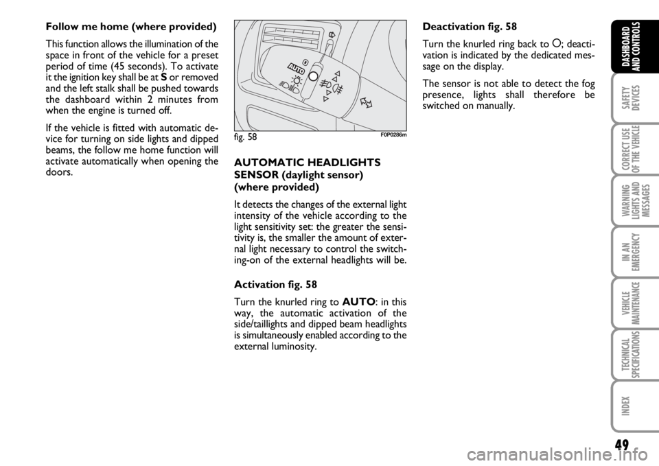
Activation fig. 58
Turn the knurled ring to AUTO: in this
way, the automatic activation of the
side/taillights and dipped beam headlights
is simultaneously enabled according to the
external luminosity.
fig. 58F0P0286m
Deactivation fig. 58
Turn the knurled ring back to å; deacti-
vation is indicated by the dedicated mes-
sage on the display.
The sensor is not able to detect the fog
presence, lights shall therefore be
switched on manually.
Page 53 of 210
52
SAFETY
DEVICES
CORRECT USE
OF THE
VEHICLE
WARNING
LIGHTS AND
MESSAGES
IN AN
EMERGENCY
VEHICLE
MAINTENANCE
TECHNICAL
SPECIFICATIONS
INDEX
DASHBOARD
AND
CONTROLS
Operating the windscreen washer with
the rain sensor activated the normal wash-
ing cycle is performed at the end of which
the rain sensor resumes its normal auto-
matic function.
So as to deactivate the rain sensor, put the
windscreen wiper command in the I, 1or
2positions. The deactivation is accompa-
nied by a message on the display.
To activate the rain sensor you have to
move the stalk to another position and
then back to AUTO.The rain sensor is able to recognize and
automatically adjust itself in the presence
of the following particular conditions:
❒impurities on the controlled surface
(salt, dirt, etc...);
❒streaks of water produced by worn
wiper blades;
❒difference between day and night (hu-
man eye is more bothered by wet glass
at night).Pulling the stalk towards the steering
wheel (unstable position), regardless of
the position of the knurled ring, operates
the windscreen washer and if the dipped
or high beams are on, also the headlight
washer (where provided).
Windscreen wiper will then perform three
wiping strokes.
Do not activate the rain sen-
sor when washing the vehi-
cle at automatic car-wash stations.
WARNING
When cleaning or washing
the windscreen make sure the
rain sensor is off.
WARNING
Do not activate the rain sen-
sor if the windscreen is icy.
WARNING
Page 59 of 210

58
SAFETY
DEVICES
CORRECT USE
OF THE
VEHICLE
WARNING
LIGHTS AND
MESSAGES
IN AN
EMERGENCY
VEHICLE
MAINTENANCE
TECHNICAL
SPECIFICATIONS
INDEX
DASHBOARD
AND
CONTROLS
F0P0343m F0P0338mF0P0330m
F0P0332mF0P0344m F0P0351m
F0P0334m
F0P0334mF0P0339m F0P0340m
Function Selection
Position the knob at the LIMITposition.
The restrictor is selected but it is not yet
active. The display indicates the last speed
programmed.
Speed Programming
This programming function can be carried
out without activating the restrictor, but
with the engine running.
In order to memorise a speed superior to
the previous one:
❒press the Set +key.
A slight pressure increases the speed by 1
km/h.
A constant pressure increases the speed
by steps of 5 km/h.
In order to memorise a speed less than
the previous one:
❒press the Set -key.
A slight pressure reduces the speed by 1
km/h.
A constant pressure reduces the speed by
steps of 5 km/h. Activation/deactivation (OFF)
By pressing the button the first time, it ac-
tivates the restrictor; a second time de-
activates it (OFF).
Page 65 of 210
If, after a crash no fuel leaks are found and
the vehicle can be started again, reset the
fuel cut-off switch as follows:
❒turn the key to S;
❒remove the ignition key; refit the key
into the ignition switch and then start
the engine.
FUEL CUT-OFF SWITCH
It is a safety switch controlled by air bag
electronic control unit that in the event of
a serious crash (in any direction) comes
into operation by cutting off fuel and turn-
ing off the engine as a consequence.
Fuel cut-off switch activation is indicated
by a dedicated message on the reconfig-
urable multifunction display.If, after a crash, you smell fu-
el or see leaks from the fuel
system, do not reset the switch to
avoid fire risk.
WARNING
64
SAFETY
DEVICES
CORRECT USE
OF THE
VEHICLE
WARNING
LIGHTS AND
MESSAGES
IN AN
EMERGENCY
VEHICLE
MAINTENANCE
TECHNICAL
SPECIFICATIONS
INDEX
DASHBOARD
AND
CONTROLS
Page 78 of 210
77
SAFETY
DEVICES
CORRECT USE
OF THE
VEHICLE
WARNING
LIGHTS AND
MESSAGES
IN AN
EMERGENCY
VEHICLE
MAINTENANCE
TECHNICAL
SPECIFICATIONS
INDEX
DASHBOARD
AND CONTROLS
ROOF RACK/SKI RACK
PRESETTING
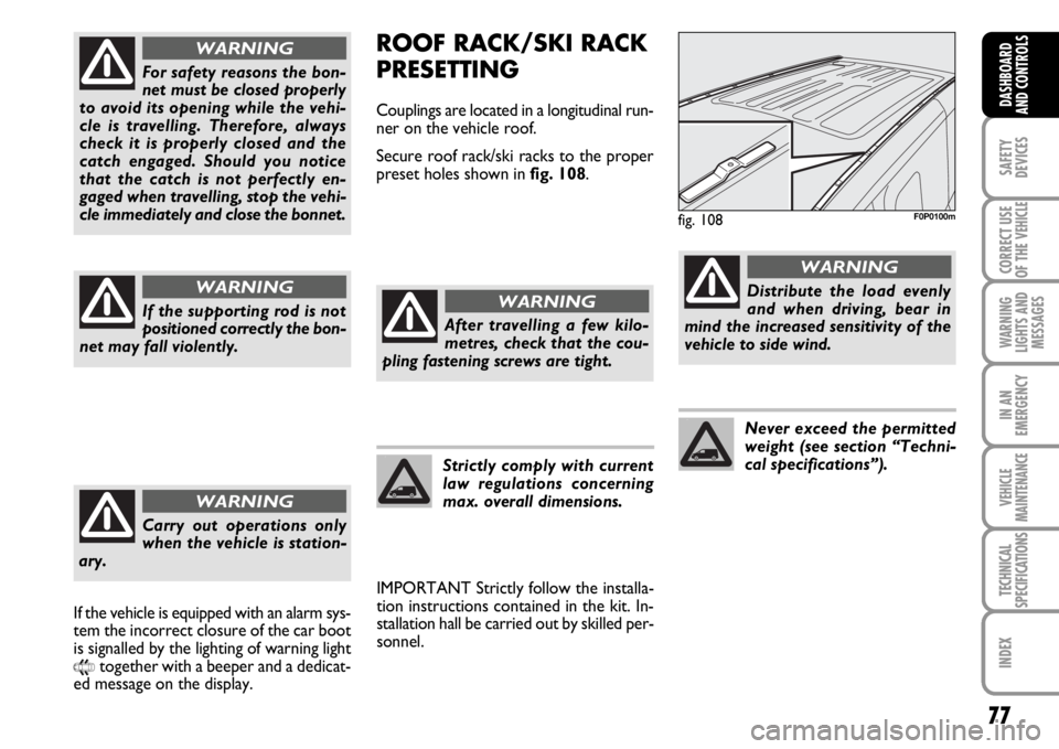
Couplings are located in a longitudinal run-
ner on the vehicle roof.
Secure roof rack/ski racks to the proper
preset holes shown in fig. 108.
IMPORTANT Strictly follow the installa-
tion instructions contained in the kit. In-
stallation hall be carried out by skilled per-
sonnel.
fig. 108F0P0100m
After travelling a few kilo-
metres, check that the cou-
pling fastening screws are tight.
WARNING
Strictly comply with current
law regulations concerning
max. overall dimensions.
Distribute the load evenly
and when driving, bear in
mind the increased sensitivity of the
vehicle to side wind.
WARNING
Never exceed the permitted
weight (see section “Techni-
cal specifications”).
For safety reasons the bon-
net must be closed properly
to avoid its opening while the vehi-
cle is travelling. Therefore, always
check it is properly closed and the
catch engaged. Should you notice
that the catch is not perfectly en-
gaged when travelling, stop the vehi-
cle immediately and close the bonnet.
WARNING
If the supporting rod is not
positioned correctly the bon-
net may fall violently.
WARNING
Carry out operations only
when the vehicle is station-
ary.
WARNING
If the vehicle is equipped with an alarm sys-
tem the incorrect closure of the car boot
is signalled by the lighting of warning light
9together with a beeper and a dedicat-
ed message on the display.
Page 84 of 210
83
SAFETY
DEVICES
CORRECT USE
OF THE
VEHICLE
WARNING
LIGHTS AND
MESSAGES
IN AN
EMERGENCY
VEHICLE
MAINTENANCE
TECHNICAL
SPECIFICATIONS
INDEX
DASHBOARD
AND CONTROLS
FAILURE INDICATIONS
ABS failure
ABS failure is indicated by the turning on
of warning light
>on the instrument pan-
el together with the message on the mul-
tifunction display (where provided), (see
section “Warning lights and messages”).
In this case the braking system is still effi-
cient, though without the aid of the ABS
system. Drive carefully to the closest Fiat
Dealership to have the system checked.BRAKE ASSIST
(emergency braking assistance
integral with ESP) (where provided)
The system, which cannot be cut out, rec-
ognizes emergency braking (on the ground
of the brake pedal operation speed) and
considerably increases the pressure in the
brake circuit.
Brake Assist is deactivated on vehicles
equipped with ESP, in the event of ESP sys-
tem failure (indicated by the switching on
of warning light
™).
When the ABS cuts in, and
you feel the brake pedal pul-
sating, do not remove your foot, but
keep it pressed; in doing so you will
stop in the shortest amount of space
possible under the current road con-
ditions.
WARNING
EBD failure
EBD failure is indicated by the turning on
of warning lights
>, xand STOP on the
instrument panel together with the mes-
sage on the multifunction display (where
provided), (see section “Warning lights
and messages”).
In this case with sharp braking the rear
wheels might lock too early, with the pos-
sibility of skidding. Drive extremely care-
fully to the nearest Fiat Dealership to have
the system checked.
If warning light xalone
comes on (together with the
message on the multifunction display,
where provided), stop the vehicle im-
mediately and contact the nearest Fi-
at Dealership. Fluid leaks from the hy-
draulic system, in fact, can compro-
mise the braking system, both tradi-
tional systems and systems with ABS.
WARNING
Page 86 of 210
85
SAFETY
DEVICES
CORRECT USE
OF THE
VEHICLE
WARNING
LIGHTS AND
MESSAGES
IN AN
EMERGENCY
VEHICLE
MAINTENANCE
TECHNICAL
SPECIFICATIONS
INDEX
DASHBOARD
AND CONTROLS
FAILURE INDICATIONS
In case of an eventual anomaly, the ESP
system automatically disconnects itself and
on the instrument panel the warning light
™is fixed, accompanied by a beeper and
a dedicated message on the display (see
chapter “Warning lights and messages”).
In which case please seek advice, as soon
as possible, from the Fiat Dealership.
Performance of the ESP sys-
tem, in terms of active safe-
ty should not induce the driver to take
pointless and unnecessary risks. The
style of driving must in any case al-
ways be adapted to the conditions of
the road surface, visibility and traffic.
Road safety is always the driver’s re-
sponsibility.
WARNING
ASR SYSTEM (Antislip Regulator)
The ASR system controls the vehicle
drive and cuts in automatically every
time one or both driving wheels slip.
In slipping conditions, two different con-
trol systems are activated:
❒ if slipping involves both driving wheels,
the ASR function intervenes reducing
the power transmitted by the engine;
❒if the slipping involves only one driving
wheel, the ASR system cuts in auto-
matically braking the wheel that is slip-
ping. The action of the ASR system is particu-
larly helpful in the following circumstances:
❒ slipping of the inner wheel due to the
effect of dynamic load changes or ex-
cessive acceleration;
❒ too much power transmitted to the
wheels also in relation to the conditions
of the road surface;
❒ acceleration on slippery, snowy or
frozen surfaces;
❒in the case of loss of grip on a wet sur-
face (aquaplaning).
For correct operation of the
ESP and ASR systems, the
tyres must absolutely be of the same
brand and type on all wheels, in per-
fect conditions and, above all, of
type, brand and size specified.
WARNING
Page 87 of 210
86
SAFETY
DEVICES
CORRECT USE
OF THE
VEHICLE
WARNING
LIGHTS AND
MESSAGES
IN AN
EMERGENCY
VEHICLE
MAINTENANCE
TECHNICAL
SPECIFICATIONS
INDEX
DASHBOARD
AND CONTROLS
MSR system
(engine braking torque control)
It is an integral part of the ASR system that
in case of sudden gear shifting, cuts in pro-
viding torque to the engine thus prevent-
ing excessive driving wheel drive that, spe-
cially in poor grip conditions, can lead to
loss of stability.Switching the system on/off
The ASR system switches on automatically
each time the engine is started.
Switching the ESP system off will auto-
matically switch off the ASR system too.
When travelling, the ASR can be switched
off and on again by pressing switch Alo-
cated on the dashboard fig. 119.
When the ASR is switched off this is
shown by the lighting up of the led
B-fig. 119on the switch and by relevant
message on the multifunction display,
where provided.
If the ASR is switched off when travelling,
it will turn on again automatically the next
time the engine is started.
When travelling on snowy roads with
snow chains, it may be helpful to turn the
ASR off: in fact, in these conditions, slip-
ping of the driving wheels when moving off
makes it possible to obtain better drive.
The performance of the sys-
tem, in terms of active safe-
ty should not induce the driver to take
pointless and unnecessary risks.
The style of driving must in any case
always be adapted to the conditions
of the road surface, visibility and traf-
fic. Road safety is always the driver’s
responsibility.
WARNING
For correct operation of the ASR system,
the tyres must absolutely be of the same
brand and type on all wheels, in perfect
conditions and, above all, of type, brand
and size specified.
FAILURE INDICATIONS
In the event of malfunctioning, the ASR
system is automatically disconnected and
the warning light
™will come with fixed
light on the instrument panel, (see section
“Warning lights and messages”).
In this case contact Fiat Dealership as soon
as possible.
Page 89 of 210
88
SAFETY
DEVICES
CORRECT USE
OF THE
VEHICLE
WARNING
LIGHTS AND
MESSAGES
IN AN
EMERGENCY
VEHICLE
MAINTENANCE
TECHNICAL
SPECIFICATIONS
INDEX
DASHBOARD
AND CONTROLS SICUREZZA
AVVIAMENTO
E GUIDA
SPIE
E MESSAGGI
IN EMERGENZA
MANUTENZIONE
E CURA
DATI TECNICI
INDICE
ALFABETICO
PARKING SENSORS
(where provided)
Parking sensors are located in the rear
bumper fig. 114and their function is to
inform the driver, through an intermittent
buzzer, about the presence of obstacles
behind the vehicle.
In order to deactivate the parking sensors,
press button A-fig. 115present between
the commands on the bridge of the cen-
tral compartment. The deactivation is sig-
nalled by the lighting of the led Bon the
button.
In order to re-activate them, press button
Aagain.
When the distance from the obstacle sit-
uated behind the vehicle diminishes, it cor-
responds with an increase in the frequen-
cy of the beeping.
WARNING The condition of the parking
sensors (activated or deactivated) is mem-
orised upon switching off the engine.BUZZER WARNINGS
When the reverse gear is engaged an in-
termittent acoustic signal is automatically
activated.
The acoustic signal:
❒becomes louder as the distance be-
tween the vehicle and the obstacle de-
creases;
❒becomes continuous when the distance
between the vehicle and the obstacle is
less than 30 cm and stops immediately
if the distance raises;
❒is constant if the distance is unvaried;
if this situation concerns the side sen-
sors, the buzzer will stop after about
3 seconds to avoid, for example, warn-
ing indications in the event of manoeu-
vres along walls.FAILURE INDICATIONS
Parking sensor failures, if any, will be in-
dicated when engaging reverse by the
buzzer and the turning on of led
B-fig. 115together with the message on
the display.
fig. 114F0P0605mfig. 115F0P0106m