FIAT SCUDO 2010 Owner handbook (in English)
Manufacturer: FIAT, Model Year: 2010, Model line: SCUDO, Model: FIAT SCUDO 2010Pages: 210, PDF Size: 3.32 MB
Page 71 of 210
70
SAFETY
DEVICES
CORRECT USE
OF THE
VEHICLE
WARNING
LIGHTS AND
MESSAGES
IN AN
EMERGENCY
VEHICLE
MAINTENANCE
TECHNICAL
SPECIFICATIONS
INDEX
DASHBOARD
AND
CONTROLS
Do not leave the vehicle
parked on a steep slope with
the sliding door open. An involuntary
knock could release the door and
make it slide.
WARNING
When leaving the vehicle
parked with the sliding doors
open, always check they are proper-
ly locked into place.
WARNING
The catch system is designed
to ensure the best comfort in
use. An accidental knock or gust of
wind could release the doors and
make them close.
WARNING
In case the vehicle is sta-
tionary with the rear doors
open at 90°, these hide the rear lights.
In order to signal your position to oth-
er drivers who are travelling in the
same direction and may not have no-
ticed the stationery vehicle, use a tri-
angular signal or any other device
prescribed by the enforced legislation
in your country.
WARNING
REAR DOUBLE
DOORS
The double rear doors are fitted with a
catch which stops the opening at an an-
gle of approximately 90°.
Opening the double doors from the outside
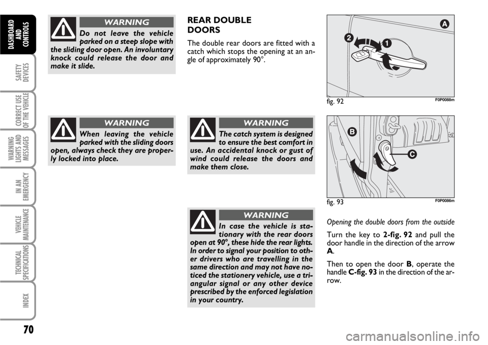
Turn the key to 2-fig. 92 and pull the
door handle in the direction of the arrow
A.
Then to open the door B, operate the
handle C-fig. 93in the direction of the ar-
row.
fig. 93F0P0086m
fig. 92F0P0088m
Page 72 of 210
71
SAFETY
DEVICES
CORRECT USE
OF THE
VEHICLE
WARNING
LIGHTS AND
MESSAGES
IN AN
EMERGENCY
VEHICLE
MAINTENANCE
TECHNICAL
SPECIFICATIONS
INDEX
DASHBOARD
AND CONTROLS
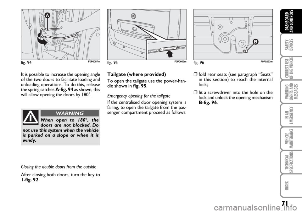
fig. 94F0P0087mfig. 95F0P0602mfig. 96F0P0293m
It is possible to increase the opening angle
of the two doors to facilitate loading and
unloading operations. To do this, release
the spring catches A-fig. 94as shown; this
will allow opening the doors by 180°.
When open to 180°, the
doors are not blocked. Do
not use this system when the vehicle
is parked on a slope or when it is
windy.
WARNING
Closing the double doors from the outside
After closing both doors, turn the key to
1-fig. 92.Tailgate (where provided)
To open the tailgate use the power-han-
dle shown in fig. 95.
Emergency opening for the tailgate
If the centralised door opening system is
failing, to open the tailgate from the pas-
senger compartment proceed as follows:
❒fold rear seats (see paragraph “Seats”
in this section) to reach the internal
lock;
❒fit a screwdriver into the hole on the
lock and unlock the opening mechanism
B-fig. 96.
Page 73 of 210

72
SAFETY
DEVICES
CORRECT USE
OF THE
VEHICLE
WARNING
LIGHTS AND
MESSAGES
IN AN
EMERGENCY
VEHICLE
MAINTENANCE
TECHNICAL
SPECIFICATIONS
INDEX
DASHBOARD
AND
CONTROLS
CENTRALISED
OPENING/CLOSURE
From the outside
Use the remote-control set in order to
lock/unlock the vehicle.
From the inside fig. 97
By pressing once on button A, it
allows the centralised locking of the
doors.
By pressing a second time it allows the un-
locking.
The command is not active when the ve-
hicle has been blocked from the outside
with the remote-control set or with the
key.
∫
Anti-aggression safety device
The system automatically locks the doors
as soon as the vehicle reaches approx. 10
km/h.
Activation/deactivation
With the key in the Mposition, press for
button Afor a long time to activate or de-
activate the function.
Loading compartment
(where provided) fig. 98
The pressure on button Ballows the lock-
ing/unlocking of the rear doors.
This function is activated upon delivery of
the vehicle. Upon request, it is possible to
deactivate this opening selection between
the passenger compartment and the load-
ing compartment. Please seek advice from
the Fiat Dealership.CHILDREN’S SAFETY DEVICE
It prevents the opening of the sliding side
doors from the inside.
To activate the device press button A-fig.
99situated between the commands on the
bridge of the central compartment.
The activation of the device is signalled by
the lighting of the led on button A.
The device remains active also by carrying
out the electrical unlocking of the doors.
fig. 99F0P00906mfig. 97F0P0085mfig. 98
B
F0P0352m
Page 74 of 210
73
SAFETY
DEVICES
CORRECT USE
OF THE
VEHICLE
WARNING
LIGHTS AND
MESSAGES
IN AN
EMERGENCY
VEHICLE
MAINTENANCE
TECHNICAL
SPECIFICATIONS
INDEX
DASHBOARD
AND CONTROLS
Always use this device when
transporting children.
WARNING
After engaging the child lock
on both rear doors, check for
proper engagement by trying to open
a rear door with the internal handle.
WARNING
SLIDING LUGGAGE
COVER
(where provided)
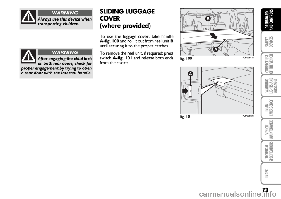
To use the luggage cover, take handle
A-fig. 100and roll it out from reel unit B
until securing it to the proper catches.
To remove the reel unit, if required: press
switch A-fig. 101and release both ends
from their seats.
fig. 100F0P0091m
fig. 101F0P0092m
Page 75 of 210
74
SAFETY
DEVICES
CORRECT USE
OF THE
VEHICLE
WARNING
LIGHTS AND
MESSAGES
IN AN
EMERGENCY
VEHICLE
MAINTENANCE
TECHNICAL
SPECIFICATIONS
INDEX
DASHBOARD
AND
CONTROLS
POWER
WINDOWS/WINDOW
WINDERS
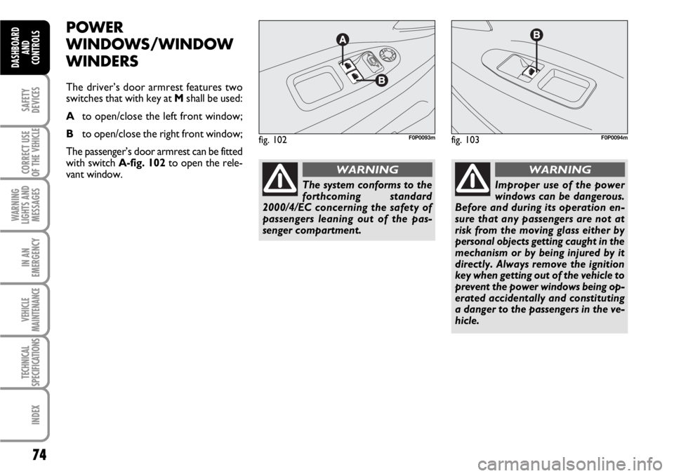
The driver’s door armrest features two
switches that with key at Mshall be used:
Ato open/close the left front window;
Bto open/close the right front window;
The passenger’s door armrest can be fitted
with switch A-fig. 102to open the rele-
vant window.
fig. 102F0P0093mfig. 103F0P0094m
Improper use of the power
windows can be dangerous.
Before and during its operation en-
sure that any passengers are not at
risk from the moving glass either by
personal objects getting caught in the
mechanism or by being injured by it
directly. Always remove the ignition
key when getting out of the vehicle to
prevent the power windows being op-
erated accidentally and constituting
a danger to the passengers in the ve-
hicle.
WARNING
The system conforms to the
forthcoming standard
2000/4/EC concerning the safety of
passengers leaning out of the pas-
senger compartment.
WARNING
Page 76 of 210

75
SAFETY
DEVICES
CORRECT USE
OF THE
VEHICLE
WARNING
LIGHTS AND
MESSAGES
IN AN
EMERGENCY
VEHICLE
MAINTENANCE
TECHNICAL
SPECIFICATIONS
INDEX
DASHBOARD
AND CONTROLS
FUNCTIONING
Manual operation
Press the button or pull it, without going
beyond the resistance point. The window
stops as soon as the command is released.
Automatic Operation
Press the button or pull it, beyond the re-
sistance point. The window opens or clos-
es completely after having released the
command: a new impulse stops the win-
dow movement.
The electrical functions of the window
winder are deactivated:
– Approx. 45 seconds after the key is tak-
en out of the switch.
– After the opening of one of the rear
doors, with the key taken out.ANTI-CRUSHING SAFETY
SYSTEM
If the vehicle is equipped with this system,
when the window rises and it meets with
an obstacle, it stops and it slightly lowers.
In case of a sudden opening of the window
upon closure, press the button until it is
completely open. Within 4 seconds, pull
the button until the window is complete-
ly closed.
During these operations, the safety sys-
tem is not active.Re-initialise of the anti-crushing
system
After a disconnection of the battery, it is
necessary to re-initialise the safety func-
tion.
Let the window lower completely and
then let it rise. It will progressively rise, a
few centimetres upon each pressure of
the button. Repeat the operation until the
window is completely open.
Keep the command pressed for at least a
second after the complete closure of the
window.
During these operations, the safety sys-
tem is not active.
Page 77 of 210
76
SAFETY
DEVICES
CORRECT USE
OF THE
VEHICLE
WARNING
LIGHTS AND
MESSAGES
IN AN
EMERGENCY
VEHICLE
MAINTENANCE
TECHNICAL
SPECIFICATIONS
INDEX
DASHBOARD
AND
CONTROLS
BONNET
IMPORTANT Before opening the bonnet,
check that windscreen wiper arms are not
lifted from the windscreen.
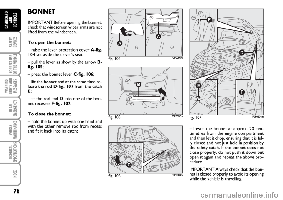
To open the bonnet:
– raise the lever protection cover A-fig.
104set aside the driver’s seat;
– pull the lever as show by the arrow B-
fig. 105;
– press the bonnet lever C-fig. 106;
– lift the bonnet and at the same time re-
lease the rod D-fig. 107from the catch
E;
– fit the rod end Dinto one of the bon-
net recesses F-fig. 107.
To close the bonnet:
– hold the bonnet up with one hand and
with the other remove rod from recess
and fit it back into its catch;
fig. 107F0P0604m
– lower the bonnet at approx. 20 cen-
timetres from the engine compartment
and then let it drop, ensuring that it is ful-
ly closed and not just held in position by
the safety catch. If the bonnet does not
close properly, do not push it down but
open it again and repeat the above pro-
cedure
IMPORTANT Always check that the bon-
net is closed properly to avoid its opening
while the vehicle is travelling.
fig. 104F0P0096m
fig. 105F0P0097m
fig. 106F0P0603m
Page 78 of 210
77
SAFETY
DEVICES
CORRECT USE
OF THE
VEHICLE
WARNING
LIGHTS AND
MESSAGES
IN AN
EMERGENCY
VEHICLE
MAINTENANCE
TECHNICAL
SPECIFICATIONS
INDEX
DASHBOARD
AND CONTROLS
ROOF RACK/SKI RACK
PRESETTING
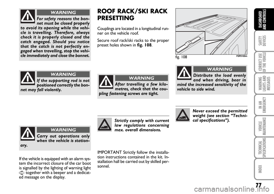
Couplings are located in a longitudinal run-
ner on the vehicle roof.
Secure roof rack/ski racks to the proper
preset holes shown in fig. 108.
IMPORTANT Strictly follow the installa-
tion instructions contained in the kit. In-
stallation hall be carried out by skilled per-
sonnel.
fig. 108F0P0100m
After travelling a few kilo-
metres, check that the cou-
pling fastening screws are tight.
WARNING
Strictly comply with current
law regulations concerning
max. overall dimensions.
Distribute the load evenly
and when driving, bear in
mind the increased sensitivity of the
vehicle to side wind.
WARNING
Never exceed the permitted
weight (see section “Techni-
cal specifications”).
For safety reasons the bon-
net must be closed properly
to avoid its opening while the vehi-
cle is travelling. Therefore, always
check it is properly closed and the
catch engaged. Should you notice
that the catch is not perfectly en-
gaged when travelling, stop the vehi-
cle immediately and close the bonnet.
WARNING
If the supporting rod is not
positioned correctly the bon-
net may fall violently.
WARNING
Carry out operations only
when the vehicle is station-
ary.
WARNING
If the vehicle is equipped with an alarm sys-
tem the incorrect closure of the car boot
is signalled by the lighting of warning light
9together with a beeper and a dedicat-
ed message on the display.
Page 79 of 210
78
SAFETY
DEVICES
CORRECT USE
OF THE
VEHICLE
WARNING
LIGHTS AND
MESSAGES
IN AN
EMERGENCY
VEHICLE
MAINTENANCE
TECHNICAL
SPECIFICATIONS
INDEX
DASHBOARD
AND
CONTROLS
PNEUMATIC
SUSPENSIONS
In some versions the tires rear suspen-
sions self-leveling may be included as an
optional.
According to versions suspensions can be
adjusted manually or automatically.
MANUAL ADJUSTMENT
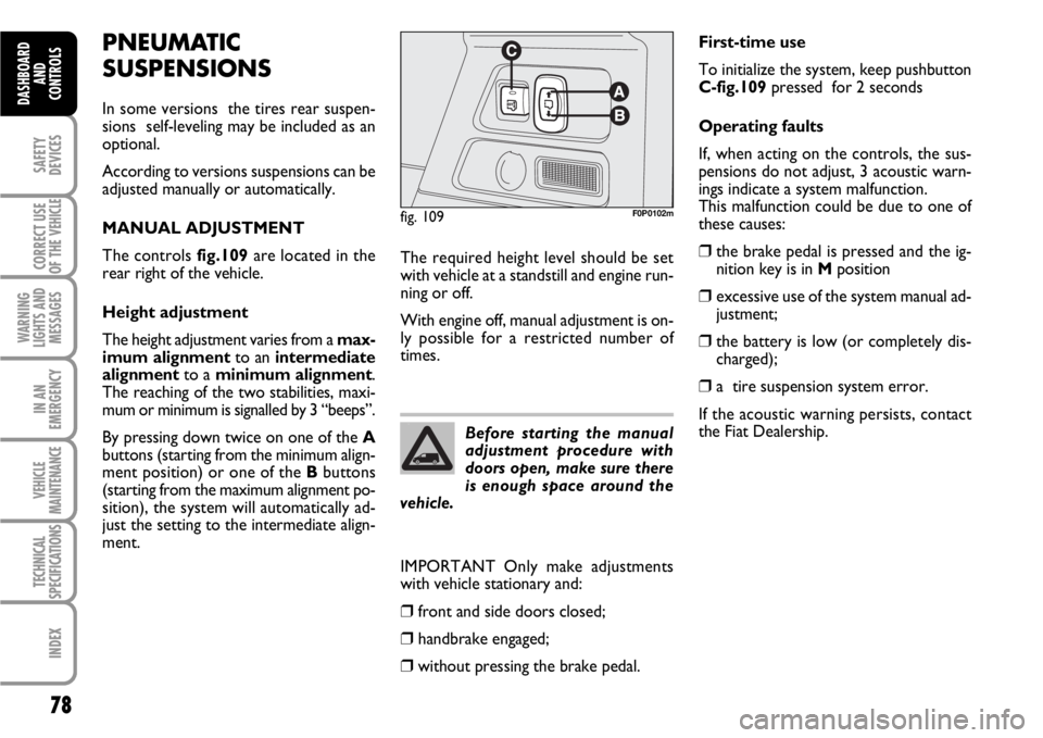
The controls fig.109are located in the
rear right of the vehicle.
Height adjustment
The height adjustment varies from a max-
imum alignmentto an intermediate
alignmentto a minimum alignment.
The reaching of the two stabilities, maxi-
mum or minimum is signalled by 3 “beeps”.
By pressing down twice on one of the A
buttons (starting from the minimum align-
ment position) or one of the Bbuttons
(starting from the maximum alignment po-
sition), the system will automatically ad-
just the setting to the intermediate align-
ment.
fig. 109F0P0102m
Before starting the manual
adjustment procedure with
doors open, make sure there
is enough space around the
vehicle.
First-time use
To initialize the system, keep pushbutton
C-fig.109pressed for 2 seconds
Operating faults
If, when acting on the controls, the sus-
pensions do not adjust, 3 acoustic warn-
ings indicate a system malfunction.
This malfunction could be due to one of
these causes:
❒the brake pedal is pressed and the ig-
nition key is in Mposition
❒excessive use of the system manual ad-
justment;
❒the battery is low (or completely dis-
charged);
❒a tire suspension system error.
If the acoustic warning persists, contact
the Fiat Dealership. The required height level should be set
with vehicle at a standstill and engine run-
ning or off.
With engine off, manual adjustment is on-
ly possible for a restricted number of
times.
IMPORTANT Only make adjustments
with vehicle stationary and:
❒front and side doors closed;
❒handbrake engaged;
❒without pressing the brake pedal.
Page 80 of 210
79
SAFETY
DEVICES
CORRECT USE
OF THE
VEHICLE
WARNING
LIGHTS AND
MESSAGES
IN AN
EMERGENCY
VEHICLE
MAINTENANCE
TECHNICAL
SPECIFICATIONS
INDEX
DASHBOARD
AND CONTROLS
AUTOMATIC ADJUSTMENT
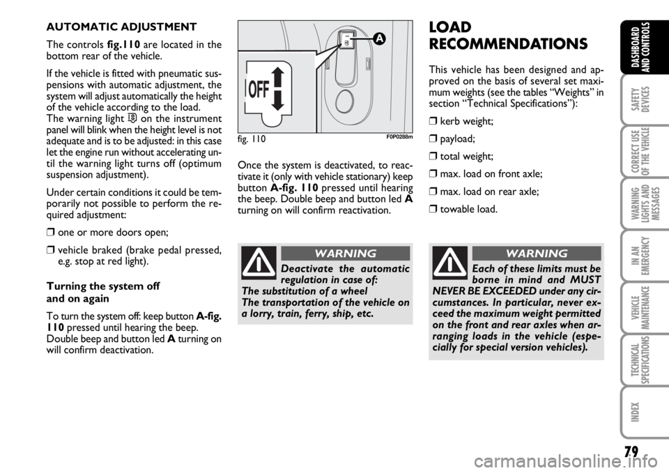
The controls fig.110are located in the
bottom rear of the vehicle.
If the vehicle is fitted with pneumatic sus-
pensions with automatic adjustment, the
system will adjust automatically the height
of the vehicle according to the load.
The warning light
…on the instrument
panel will blink when the height level is not
adequate and is to be adjusted: in this case
let the engine run without accelerating un-
til the warning light turns off (optimum
suspension adjustment).
Under certain conditions it could be tem-
porarily not possible to perform the re-
quired adjustment:
❒one or more doors open;
❒vehicle braked (brake pedal pressed,
e.g. stop at red light).
Turning the system off
and on again
To turn the system off: keep button A-fig.
110pressed until hearing the beep.
Double beep and button led Aturning on
will confirm deactivation.Once the system is deactivated, to reac-
tivate it (only with vehicle stationary) keep
button A-fig. 110pressed until hearing
the beep. Double beep and button led A
turning on will confirm reactivation.
fig. 110F0P0288m
LOAD
RECOMMENDATIONS
This vehicle has been designed and ap-
proved on the basis of several set maxi-
mum weights (see the tables “Weights” in
section “Technical Specifications”):
❒kerb weight;
❒payload;
❒total weight;
❒max. load on front axle;
❒max. load on rear axle;
❒towable load.
Each of these limits must be
borne in mind and MUST
NEVER BE EXCEEDED under any cir-
cumstances. In particular, never ex-
ceed the maximum weight permitted
on the front and rear axles when ar-
ranging loads in the vehicle (espe-
cially for special version vehicles).
WARNING
Deactivate the automatic
regulation in case of:
The substitution of a wheel
The transportation of the vehicle on
a lorry, train, ferry, ship, etc.
WARNING