wheel FIAT SEDICI 2009 2.G Owners Manual
[x] Cancel search | Manufacturer: FIAT, Model Year: 2009, Model line: SEDICI, Model: FIAT SEDICI 2009 2.GPages: 270, PDF Size: 3.44 MB
Page 23 of 270
22
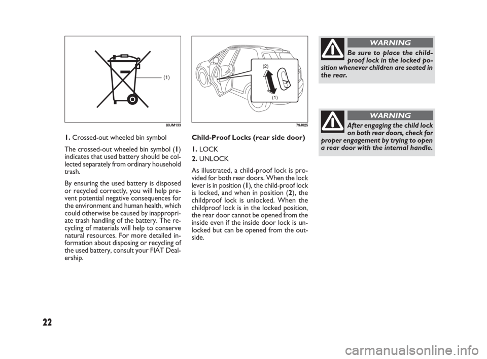
Child-Proof Locks (rear side door)
1. LOCK
2.UNLOCK
As illustrated, a child-proof lock is pro-
vided for both rear doors. When the lock
lever is in position (1), the child-proof lock
is locked, and when in position (2), the
childproof lock is unlocked. When the
childproof lock is in the locked position,
the rear door cannot be opened from the
inside even if the inside door lock is un-
locked but can be opened from the out-
side.
(1) (2)
79J025
Be sure to place the child-
proof lock in the locked po-
sition whenever children are seated in
the rear.
WARNING
1.Crossed-out wheeled bin symbol
The crossed-out wheeled bin symbol (1)
indicates that used battery should be col-
lected separately from ordinary household
trash.
By ensuring the used battery is disposed
or recycled correctly, you will help pre-
vent potential negative consequences for
the environment and human health, which
could otherwise be caused by inappropri-
ate trash handling of the battery. The re-
cycling of materials will help to conserve
natural resources. For more detailed in-
formation about disposing or recycling of
the used battery, consult your FIAT Deal-
ership.
After engaging the child lock
on both rear doors, check for
proper engagement by trying to open
a rear door with the internal handle.
WARNING
(1)
80JM133
009-056 SEDICI LUM FL GB 1E 19-06-2009 14:11 Pagina 22
Page 49 of 270
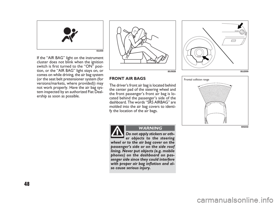
FRONT AIR BAGS
The driver’s front air bag is located behind
the center pad of the steering wheel and
the front passenger’s front air bag is lo-
cated behind the passenger’s side of the
dashboard. The words “SRS AIRBAG” are
molded into the air bag covers to identi-
fy the location of the air bags. If the “AIR BAG” light on the instrument
cluster does not blink when the ignition
switch is first turned to the “ON” posi-
tion, or the “AIR BAG” light stays on, or
comes on while driving, the air bag system
(or the seat belt pretensioner system (for
versions/markets, where provided)) may
not work properly. Have the air bag sys-
tem inspected by an authorized Fiat Deal-
ership as soon as possible.
63J030
80JS02680J2009
60G032
Frontal collision range
Do not apply stickers or oth-
er objects to the steering
wheel or to the air bag cover on the
passenger’s side or on the side roof
lining. Never put objects (e.g. mobile
phones) on the dashboard on pas-
senger side since they could interfere
with proper air bag inflation and al-
so cause serious injury.
WARNING
48
009-056 SEDICI LUM FL GB 1E 19-06-2009 14:11 Pagina 48
Page 54 of 270
53
54G582
Air bags must inflate quickly and forceful-
ly in order to reduce the chance of seri-
ous or fatal injuries. However, an un-
avoidable consequence of the quick infla-
tion is that the air bag may irritate bare
skin, such as the facial area against a front
air bag. Also, upon inflation, a loud noise
will occur and some powder and smoke
will be released. These conditions are not
harmful and do not indicate a fire in the
car. Be aware, however, that some air bag
components may be hot for a while after
inflation.
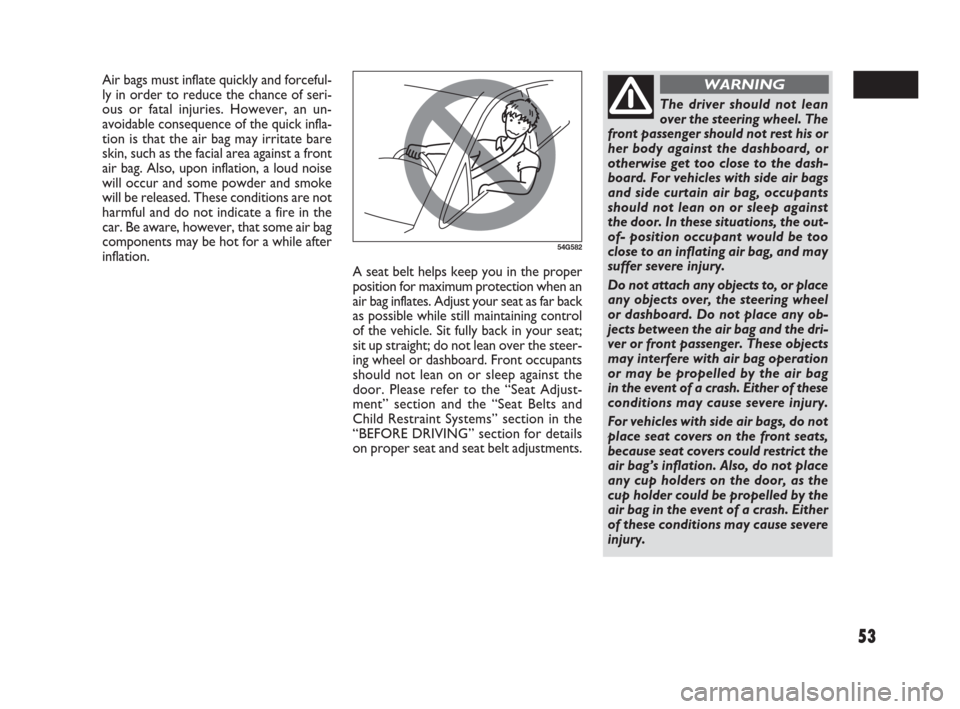
The driver should not lean
over the steering wheel. The
front passenger should not rest his or
her body against the dashboard, or
otherwise get too close to the dash-
board. For vehicles with side air bags
and side curtain air bag, occupants
should not lean on or sleep against
the door. In these situations, the out-
of- position occupant would be too
close to an inflating air bag, and may
suffer severe injury.
Do not attach any objects to, or place
any objects over, the steering wheel
or dashboard. Do not place any ob-
jects between the air bag and the dri-
ver or front passenger. These objects
may interfere with air bag operation
or may be propelled by the air bag
in the event of a crash. Either of these
conditions may cause severe injury.
For vehicles with side air bags, do not
place seat covers on the front seats,
because seat covers could restrict the
air bag’s inflation. Also, do not place
any cup holders on the door, as the
cup holder could be propelled by the
air bag in the event of a crash. Either
of these conditions may cause severe
injury.
WARNING
A seat belt helps keep you in the proper
position for maximum protection when an
air bag inflates. Adjust your seat as far back
as possible while still maintaining control
of the vehicle. Sit fully back in your seat;
sit up straight; do not lean over the steer-
ing wheel or dashboard. Front occupants
should not lean on or sleep against the
door. Please refer to the “Seat Adjust-
ment” section and the “Seat Belts and
Child Restraint Systems” section in the
“BEFORE DRIVING” section for details
on proper seat and seat belt adjustments.
009-056 SEDICI LUM FL GB 1E 19-06-2009 14:11 Pagina 53
Page 59 of 270
58
IGNITION SWITCH
VEHICLE WITHOUT KEYLESS
START SYSTEM
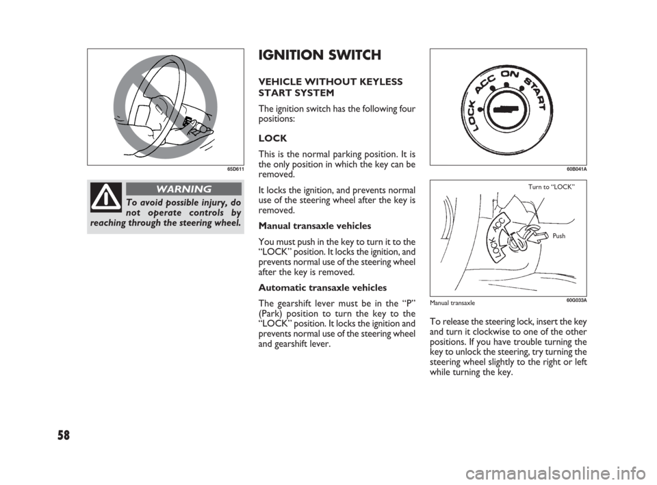
The ignition switch has the following four
positions:
LOCK
This is the normal parking position. It is
the only position in which the key can be
removed.
It locks the ignition, and prevents normal
use of the steering wheel after the key is
removed.
Manual transaxle vehicles
You must push in the key to turn it to the
“LOCK” position. It locks the ignition, and
prevents normal use of the steering wheel
after the key is removed.
Automatic transaxle vehicles
The gearshift lever must be in the “P”
(Park) position to turn the key to the
“LOCK” position. It locks the ignition and
prevents normal use of the steering wheel
and gearshift lever.
65D611
To avoid possible injury, do
not operate controls by
reaching through the steering wheel.
WARNING
60G033A
Turn to “LOCK”
Push
60B041A
To release the steering lock, insert the key
and turn it clockwise to one of the other
positions. If you have trouble turning the
key to unlock the steering, try turning the
steering wheel slightly to the right or left
while turning the key.
Manual transaxle
057-070 SEDICI LUM FL GB 1E 19-06-2009 10:32 Pagina 58
Page 60 of 270
59
ACC
Accessories such as the radio can oper-
ate, but the engine is off.
ON
This is the normal operating position.
All electrical systems are on.
START
This is the position for starting the engine
using the starter motor. The key should
be released from this position as soon as
the engine starts.
Ignition key reminder
(for versions/markets, where provided)
A buzzer sounds intermittently to remind
you to remove the ignition key if it is in
the ignition switch when the driver’s door
is opened.
If the ignition device is tam-
pered with (e.g.: attempted
theft), have it checked over by a Fiat
Dealership as soon as possible.
WARNING
When getting out of the ve-
hicle, always remove the key
to prevent any occupants from acci-
dentally activating the controls. Re-
member to engage the handbrake
and if the vehicle is parked on uphill
slope to engage the first gear. If the
vehicle is facing downhill, engage the
reverse gear. Never leave unsuper-
vised children in the vehicle.
WARNING
Never remove the ignition
key while the vehicle is mov-
ing. The steering wheel would auto-
matically lock as soon as you try to
turn it. This also applies when the ve-
hicle is being towed.
WARNING
It is absolutely forbidden to
carry out whatever after-
market operation involving steering
system or steering column modifica-
tions (e.g.: installation of anti-theft
device) that could badly affect per-
formance and safety, cause the lapse
of warranty and also result in non-
compliance of the vehicle with ho-
mologation requirements.
WARNING
057-070 SEDICI LUM FL GB 1E 19-06-2009 10:32 Pagina 59
Page 62 of 270
61
IMPORTANT The remote controller is
a sensitive electronic instrument. To avoid
damaging the remote controller:
❒Do not expose it to impacts, moisture
or high temperature such as on the
dashboard under direct sunlight.
❒Keep the remote controller away from
magnetic objects such as a television.
You can also turn the ignition switch by
inserting the ignition key into the slot.
If you leave any of the doors open with the
ignition switch in the “ACC” position for
a while (and no key inserted), the engine
may not start when you turn the ignition
switch to “START”. If the engine does not
start, close all doors completely or turn
the ignition switch back to the “LOCK”
position, then start the engine.
The ignition switch has the following four
positions:ACC (2)
Accessories such as the radio can oper-
ate, but the engine is off.
ON (3)
This is the normal operating position. All
electrical systems are on.
START (4)
This is the position for starting the engine
using the starter motor. The switch should
be released from this position as soon as
the engine starts.
Ignition switch reminder
(When using the keyless start system)
A buzzer sounds intermittently to remind
you to return the ignition switch to the
“LOCK” position if it is in the “ACC” po-
sition when the driver’s door is opened. LOCK (1)
This is the normal parking position. It is
the only position in which the key can be
removed. It locks the ignition, and pre-
vents normal use of the steering wheel.
If your vehicle is equipped with the auto-
matic transaxle key inter lock system, the
ignition switch can be turned to the
“LOCK” position only when the gearshift
lever is in the “P” (Park) position.
To release the steering lock, turn the ig-
nition switch clockwise to one of the oth-
er positions. If you have trouble turning
the ignition switch to unlock the steer-
ing, try turning the steering wheel slightly
to the right or left while turning the
switch.
Manual transaxle vehicle
You must push in the ignition switch to
turn it from the “LOCK” position to the
“ACC” position. To return to the
“LOCK” position from the “ACC” posi-
tion, turn the ignition switch counter-
clockwise while pushing in the switch.
Automatic transaxle vehicle
To turn the ignition switch, push the
switch.
057-070 SEDICI LUM FL GB 1E 19-06-2009 10:32 Pagina 61
Page 63 of 270
62
81A297S
(1)
80JM139
Never return the ignition
switch to the “LOCK” posi-
tion and remove the ignition key
while the vehicle is moving. The steer-
ing wheel will lock and you will not be
able to steer the vehicle.
Always return the ignition switch to
the “LOCK” position and remove the
ignition key when leaving the vehicle
even if a short time. Also do not leave
children alone in a parked vehicle.
Unattended children could cause ac-
cidental movement of the vehicle or
could tamper with power windows or
power sunroof. They also could suf-
fer from heat stroke in warm or hot
weather. These could result in severe
injury or even death.
WARNING
IMPORTANT
❒Do not use the starter motor for more
than 15 seconds at a time. For diesel
engine model, do not use the starter
motor for more than 30 seconds at a
time. If the engine does not start, wait
15 seconds before trying again. If the
engine does not start after several at-
tempts, check the fuel and ignition sys-
tems or consult your Fiat Dealership.
❒Do not leave the ignition switch in the
“ON” position if the engine is not run-
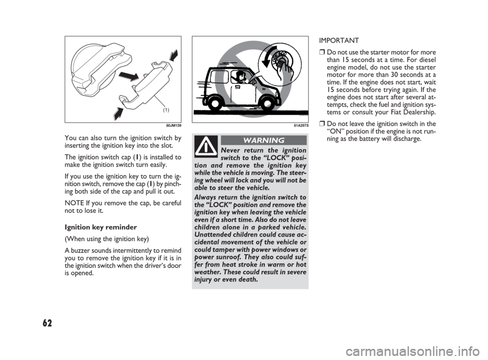
ning as the battery will discharge. You can also turn the ignition switch by
inserting the ignition key into the slot.
The ignition switch cap (1) is installed to
make the ignition switch turn easily.
If you use the ignition key to turn the ig-
nition switch, remove the cap (1) by pinch-
ing both side of the cap and pull it out.
NOTE If you remove the cap, be careful
not to lose it.
Ignition key reminder
(When using the ignition key)
A buzzer sounds intermittently to remind
you to remove the ignition key if it is in
the ignition switch when the driver’s door
is opened.
057-070 SEDICI LUM FL GB 1E 19-06-2009 10:32 Pagina 62
Page 65 of 270
64
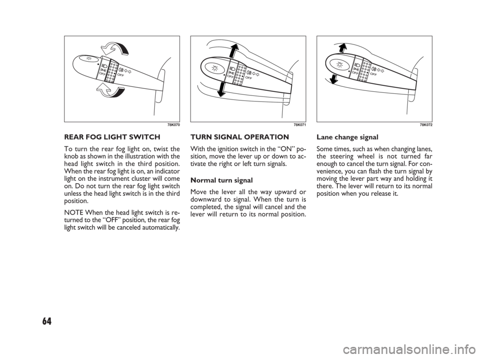
TURN SIGNAL OPERATION
With the ignition switch in the “ON” po-
sition, move the lever up or down to ac-
tivate the right or left turn signals.
Normal turn signal
Move the lever all the way upward or
downward to signal. When the turn is
completed, the signal will cancel and the
lever will return to its normal position.Lane change signal
Some times, such as when changing lanes,
the steering wheel is not turned far
enough to cancel the turn signal. For con-
venience, you can flash the turn signal by
moving the lever part way and holding it
there. The lever will return to its normal
position when you release it. REAR FOG LIGHT SWITCH
To turn the rear fog light on, twist the
knob as shown in the illustration with the
head light switch in the third position.
When the rear fog light is on, an indicator
light on the instrument cluster will come
on. Do not turn the rear fog light switch
unless the head light switch is in the third
position.
NOTE When the head light switch is re-
turned to the “OFF” position, the rear fog
light switch will be canceled automatically.
78K07078K07178K072
057-070 SEDICI LUM FL GB 1E 19-06-2009 10:32 Pagina 64
Page 68 of 270
67
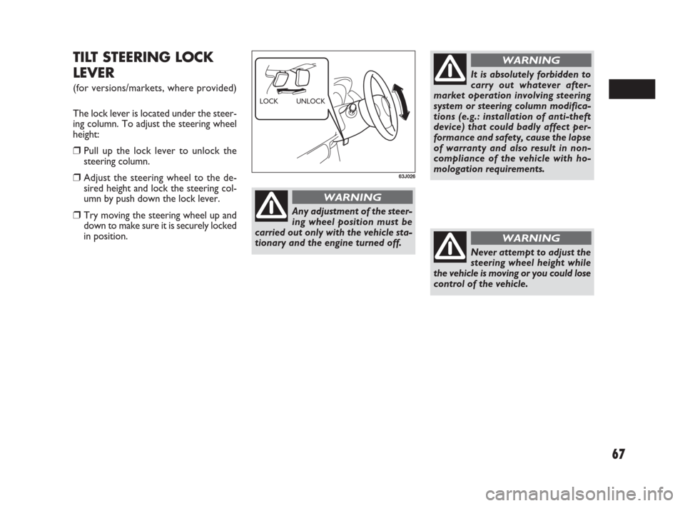
TILT STEERING LOCK
LEVER
(for versions/markets, where provided)
The lock lever is located under the steer-
ing column. To adjust the steering wheel
height:
❒Pull up the lock lever to unlock the
steering column.
❒Adjust the steering wheel to the de-
sired height and lock the steering col-
umn by push down the lock lever.
❒Try moving the steering wheel up and
down to make sure it is securely locked
in position.
63J026
UNLOCK LOCK
Never attempt to adjust the
steering wheel height while
the vehicle is moving or you could lose
control of the vehicle.
WARNING
Any adjustment of the steer-
ing wheel position must be
carried out only with the vehicle sta-
tionary and the engine turned off.
WARNING
It is absolutely forbidden to
carry out whatever after-
market operation involving steering
system or steering column modifica-
tions (e.g.: installation of anti-theft
device) that could badly affect per-
formance and safety, cause the lapse
of warranty and also result in non-
compliance of the vehicle with ho-
mologation requirements.
WARNING
057-070 SEDICI LUM FL GB 1E 19-06-2009 10:32 Pagina 67
Page 69 of 270
68
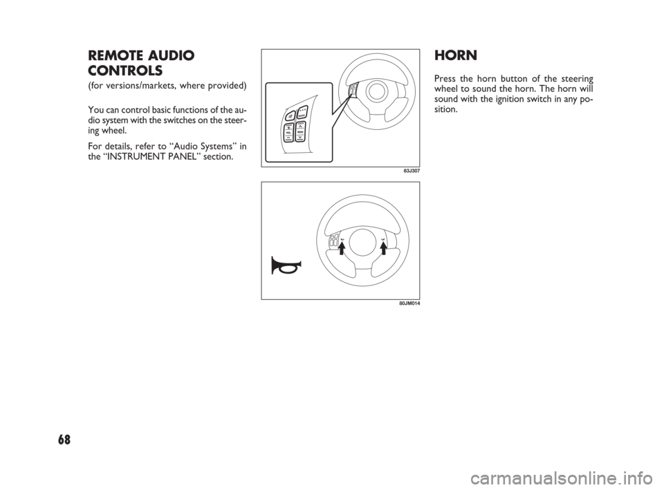
HORN
Press the horn button of the steering
wheel to sound the horn. The horn will
sound with the ignition switch in any po-
sition.
63J307
REMOTE AUDIO
CONTROLS
(for versions/markets, where provided)
You can control basic functions of the au-
dio system with the switches on the steer-
ing wheel.
For details, refer to “Audio Systems” in
the “INSTRUMENT PANEL” section.
80JM014
057-070 SEDICI LUM FL GB 1E 19-06-2009 17:04 Pagina 68