display FIAT SPIDER ABARTH 2017 Owner's Manual
[x] Cancel search | Manufacturer: FIAT, Model Year: 2017, Model line: SPIDER ABARTH, Model: FIAT SPIDER ABARTH 2017Pages: 292, PDF Size: 9.24 MB
Page 163 of 292
Note: Accelerate the vehicle to speed
up temporarily with the accelerator
pedal when the Speed Control is on.
Increasing the speed will not interfere
with, or change the set speed. Take
your foot off the accelerator to return to
the set speed.
Decreasing Speed
To decrease speed using the Speed
Control buttons:
Push the SET (-) button and hold it ,
the vehicle will gradually slow down.
Release the button at the desired
speed.
Push the SET (-) button and release
it immediately to adjust the set speed.
Multiple button pushes will decrease
the set speed according to the number
of times it is pushed.
Decreasing speed with a single SET
(-) button operation:
If the instrument cluster display for
vehicle speed is indicated in mph: the
speed will decrease in 1 mph
increments.
If the instrument cluster display for
vehicle speed is indicated in km/h: the
speed will decrease in 1 km/h
increments. Resume Speed
If any other method besides the
OFF/CAN button was used to cancel
cruising speed (such as applying the
brake pedal or pressing in the clutch
pedal) and the system is still activated,
the most recent set speed will
automatically resume when the RES (+)
button is pushed.
If vehicle speed is below 25 mph
(40 km/h), increase the vehicle speed
up to 16 mph (25 km/h) or more and
push RES (+) button.
Temporarily Canceling
The System
Warning!Leaving the Speed Control system on
when not in use is dangerous. You could
accidentally set the system or cause it to
go faster than you want. You could lose
control and have an accident. Always leave
the system OFF when you are not using it.
To temporarily cancel the system, use
one of these methods:
Slightly press the brake pedal.
Press the clutch pedal (if equipped
with a manual transmission). Push OFF/CAN button.
If the RES (+) button is pushed when
the vehicle speed is 25 mph (40 km/h)
or higher, the system reverts to the
previously set speed.
Note: If any of the following conditions
occur, the Speed Control system is
temporarily canceled:
The parking brake is applied.
Automatic Transmission: the
gear selector is in the PARK or
NEUTRAL position.
Manual Transmission: the gear
selector is in the NEUTRAL position.
Automatic Transmission: the
Speed Control cannot be canceled
while driving in manual mode (gear
selector shifted from D to M position).
Therefore, engine braking will not be
applied even if the transmission is
shifted down to a lower gear. If
deceleration is required, lower the set
speed or press the brake pedal.
When the Speed Control system is
temporarily canceled, the speed cannot
be reset.
161
Page 169 of 292
PARKVIEW REAR
BACKUP CAMERA —
IF EQUIPPED Operation
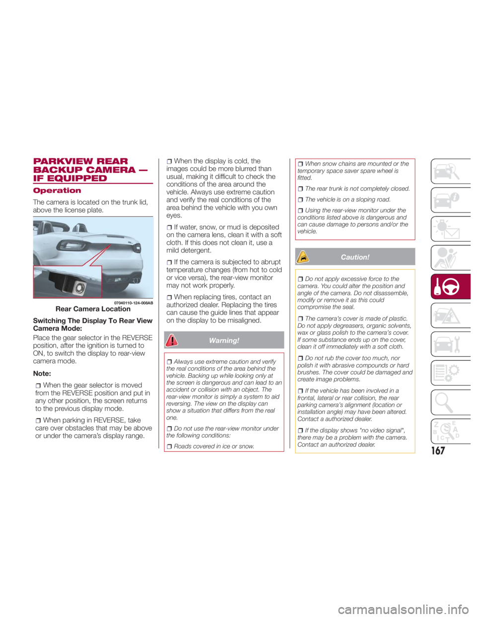
The camera is located on the trunk lid,
above the license plate.
Switching The Display To Rear View
Camera Mode:
Place the gear selector in the REVERSE
position, after the ignition is turned to
ON, to switch the display to rear-view
camera mode.
Note:
When the gear selector is moved
from the REVERSE position and put in
any other position, the screen returns
to the previous display mode.
When parking in REVERSE, take
care over obstacles that may be above
or under the camera’s display range. When the display is cold, the
images could be more blurred than
usual, making it difficult to check the
conditions of the area around the
vehicle. Always use extreme caution
and verify the real conditions of the
area behind the vehicle with you own
eyes.
If water, snow, or mud is deposited
on the camera lens, clean it with a soft
cloth. If this does not clean it, use a
mild detergent.
If the camera is subjected to abrupt
temperature changes (from hot to cold
or vice versa), the rear-view monitor
may not work properly.
When replacing tires, contact an
authorized dealer. Replacing the tires
can cause the guide lines that appear
on the display to be misaligned.
Warning!Always use extreme caution and verify
the real conditions of the area behind the
vehicle. Backing up while looking only at
the screen is dangerous and can lead to an
accident or collision with an object. The
rear-view monitor is simply a system to aid
reversing. The view on the display can
show a situation that differs from the real
one.
Do not use the rear-view monitor under
the following conditions:
Roads covered in ice or snow. When snow chains are mounted or the
temporary space saver spare wheel is
fitted.
The rear trunk is not completely closed.
The vehicle is on a sloping road.
Using the rear-view monitor under the
conditions listed above is dangerous and
can cause damage to persons and/or the
vehicle.
Caution! Do not apply excessive force to the
camera. You could alter the position and
angle of the camera. Do not disassemble,
modify or remove it as this could
compromise the seal.
The camera’s cover is made of plastic.
Do not apply degreasers, organic solvents,
wax or glass polish to the camera’s cover.
If some substance ends up on the cover,
clean it off immediately with a soft cloth.
Do not rub the cover too much, nor
polish it with abrasive compounds or hard
brushes. The cover could be damaged and
create image problems.
If the vehicle has been involved in a
frontal, lateral or rear collision, the rear
parking camera’s alignment (location or
installation angle) may have been altered.
Contact a authorized dealer.
If the display shows "no video signal",
there may be a problem with the camera.
Contact an authorized dealer.07040110-124-008AB
Rear Camera Location
167
Page 170 of 292
Display
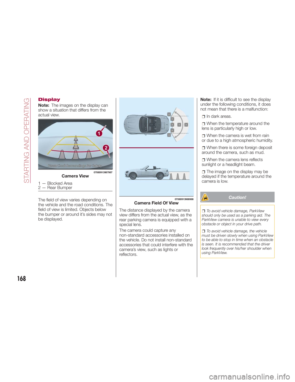
Note: The images on the display can
show a situation that differs from the
actual view.
The field of view varies depending on
the vehicle and the road conditions. The
field of view is limited. Objects below
the bumper or around it’s sides may not
be displayed. The distance displayed by the camera
view differs from the actual view, as the
rear parking camera is equipped with a
special lens.
The camera could capture any
non-standard accessories installed on
the vehicle. Do not install non-standard
accessories that could interfere with the
camera’s view, such as lights or
reflectors. Note: If it is difficult to see the display
under the following conditions, it does
not mean that there is a malfunction:
In dark areas.
When the temperature around the
lens is particularly high or low.
When the camera is wet from rain
or due to a high atmospheric humidity.
When there is some foreign deposit
around the camera, such as mud.
When the camera lens reflects
sunlight or a headlight beam.
The image on the display may be
delayed if the temperature around the
camera is low.
Caution! To avoid vehicle damage, ParkView
should only be used as a parking aid. The
ParkView camera is unable to view every
obstacle or object in your drive path.
To avoid vehicle damage, the vehicle
must be driven slowly when using ParkView
to be able to stop in time when an obstacle
is seen. It is recommended that the driver
look frequently over his/her shoulder when
using ParkView.07080913987987
Camera View
1—BlockedArea
2 — Rear Bumper 07080913988988
Camera Field Of View
168
STARTING AND OPERATING
Page 171 of 292
Looking At The Display
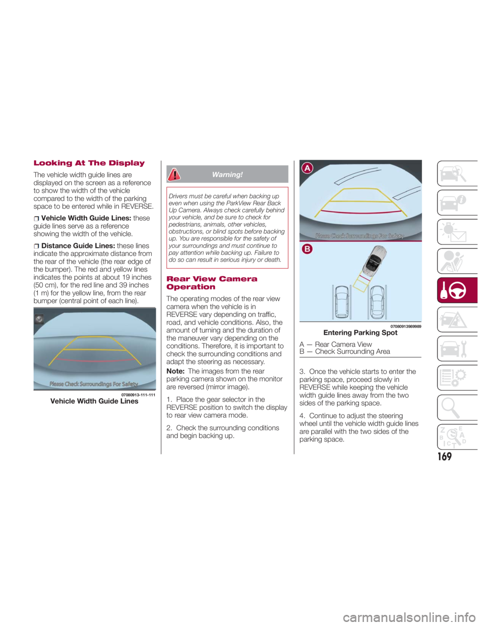
The vehicle width guide lines are
displayed on the screen as a reference
to show the width of the vehicle
compared to the width of the parking
space to be entered while in REVERSE.
Vehicle Width Guide Lines: these
guide lines serve as a reference
showing the width of the vehicle.
Distance Guide Lines: these lines
indicate the approximate distance from
the rear of the vehicle (the rear edge of
the bumper). The red and yellow lines
indicates the points at about 19 inches
(50 cm), for the red line and 39 inches
(1 m) for the yellow line, from the rear
bumper (central point of each line). Warning!Drivers must be careful when backing up
even when using the ParkView Rear Back
Up Camera. Always check carefully behind
your vehicle, and be sure to check for
pedestrians, animals, other vehicles,
obstructions, or blind spots before backing
up. You are responsible for the safety of
your surroundings and must continue to
pay attention while backing up. Failure to
do so can result in serious injury or death.
Rear View Camera
Operation
The operating modes of the rear view
camera when the vehicle is in
REVERSE vary depending on traffic,
road, and vehicle conditions. Also, the
amount of turning and the duration of
the maneuver vary depending on the
conditions. Therefore, it is important to
check the surrounding conditions and
adapt the steering as necessary.
Note: The images from the rear
parking camera shown on the monitor
are reversed (mirror image).
1. Place the gear selector in the
REVERSE position to switch the display
to rear view camera mode.
2. Check the surrounding conditions
and begin backing up. 3. Once the vehicle starts to enter the
parking space, proceed slowly in
REVERSE while keeping the vehicle
width guide lines away from the two
sides of the parking space.
4. Continue to adjust the steering
wheel until the vehicle width guide lines
are parallel with the two sides of the
parking space.07080913-111-111
Vehicle Width Guide Lines 07080913989989
Entering Parking Spot
A — Rear Camera View
B — Check Surrounding Area
169
Page 172 of 292
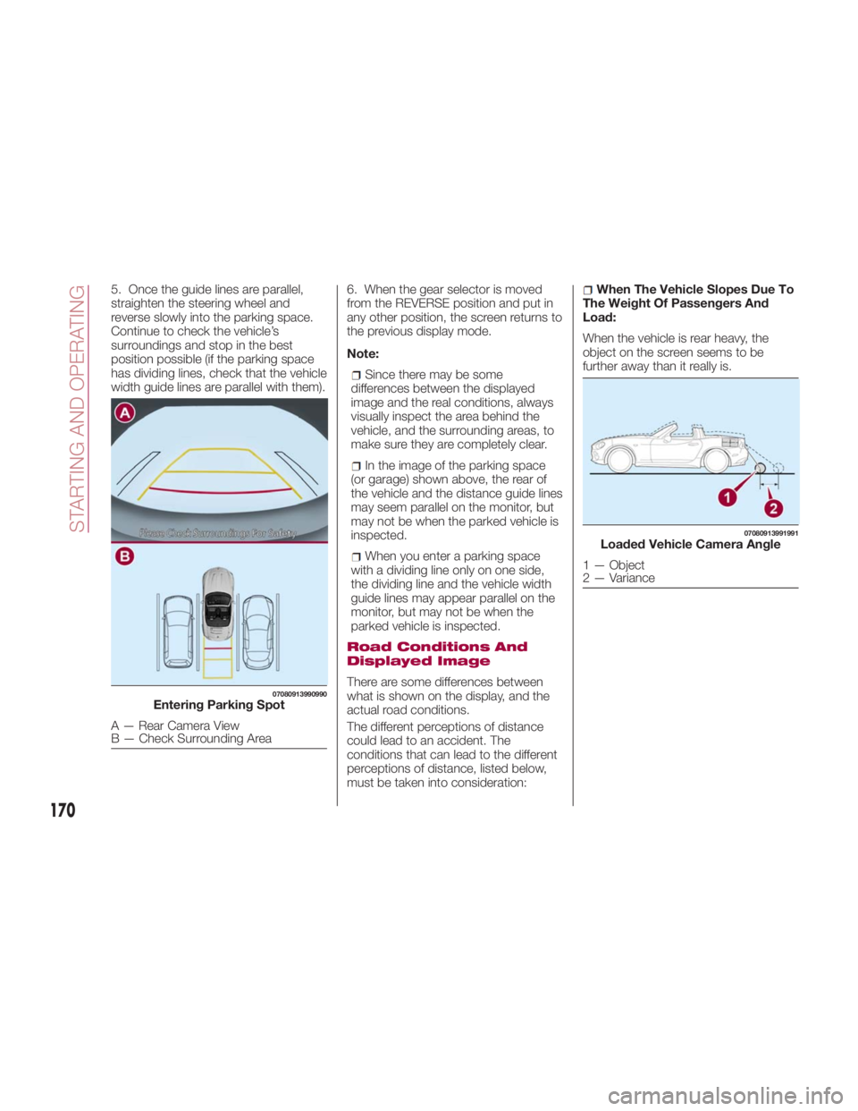
5. Once the guide lines are parallel,
straighten the steering wheel and
reverse slowly into the parking space.
Continue to check the vehicle’s
surroundings and stop in the best
position possible (if the parking space
has dividing lines, check that the vehicle
width guide lines are parallel with them). 6. When the gear selector is moved
from the REVERSE position and put in
any other position, the screen returns to
the previous display mode.
Note:
Since there may be some
differences between the displayed
image and the real conditions, always
visually inspect the area behind the
vehicle, and the surrounding areas, to
make sure they are completely clear.
In the image of the parking space
(or garage) shown above, the rear of
the vehicle and the distance guide lines
may seem parallel on the monitor, but
may not be when the parked vehicle is
inspected.
When you enter a parking space
with a dividing line only on one side,
the dividing line and the vehicle width
guide lines may appear parallel on the
monitor, but may not be when the
parked vehicle is inspected.
Road Conditions And
Displayed Image
There are some differences between
what is shown on the display, and the
actual road conditions.
The different perceptions of distance
could lead to an accident. The
conditions that can lead to the different
perceptions of distance, listed below,
must be taken into consideration: When The Vehicle Slopes Due To
The Weight Of Passengers And
Load:
When the vehicle is rear heavy, the
object on the screen seems to be
further away than it really is.07080913990990
Entering Parking Spot
A — Rear Camera View
B — Check Surrounding Area 07080913991991
Loaded Vehicle Camera Angle
1 — Object
2 — Variance
170
STARTING AND OPERATING
Page 173 of 292
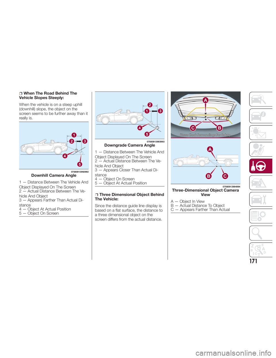
When The Road Behind The
Vehicle Slopes Steeply:
When the vehicle is on a steep uphill
(downhill) slope, the object on the
screen seems to be further away than it
really is.
Three Dimensional Object Behind
The Vehicle:
Since the distance guide line display is
based on a flat surface, the distance to
a three dimensional object on the
screen differs from the actual distance. 07080913992992
Downhill Camera Angle
1 — Distance Between The Vehicle And
Object Displayed On The Screen
2 — Actual Distance Between The Ve-
hicle And Object
3 — Appears Farther Than Actual Di-
stance
4 — Object At Actual Position
5 — Object On Screen 07080913993993
Downgrade Camera Angle
1 — Distance Between The Vehicle And
Object Displayed On The Screen
2 — Actual Distance Between The Ve-
hicle And Object
3 — Appears Closer Than Actual Di-
stance
4 — Object On Screen
5 — Object At Actual Position 07080913994994
Three-Dimensional Object Camera
View
A—ObjectInView
B — Actual Distance To Object
C — Appears Farther Than Actual
171
Page 174 of 292
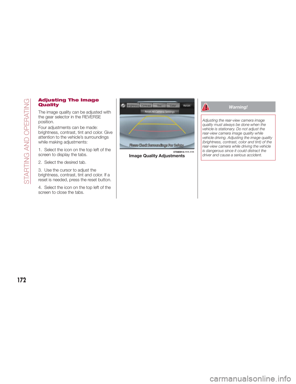
Adjusting The Image
Quality
The image quality can be adjusted with
the gear selector in the REVERSE
position.
Four adjustments can be made:
brightness, contrast, tint and color. Give
attention to the vehicle’s surroundings
while making adjustments:
1. Select the icon on the top left of the
screen to display the tabs.
2. Select the desired tab.
3. Use the cursor to adjust the
brightness, contrast, tint and color. If a
reset is needed, press the reset button.
4. Select the icon on the top left of the
screen to close the tabs. Warning!Adjusting the rear-view camera image
quality must always be done when the
vehicle is stationary. Do not adjust the
rear-view camera image quality while
vehicle driving. Adjusting the image quality
(brightness, contrast, color and tint) of the
rear-view camera while driving the vehicle
is dangerous since it could distract the
driver and cause a serious accident. 07080914-111-111
Image Quality Adjustments
172
STARTING AND OPERATING
Page 226 of 292
INTRODUCTION Be extremely careful and prevent injury
to yourself and others or damage to
your vehicle when using this Owner’s
Manual for inspection and maintenance.
If you are unsure about any procedure it
describes, we strongly urge you to have
a reliable and qualified service shop
perform the work, preferably at your
authorized dealer.
Factory-trained FCA technicians and
genuine FCA parts are best for your
vehicle. Without this expertise and the
parts that have been designed and
made especially for your vehicle,
inadequate, incomplete, and insufficient
servicing may result in problems. This
could lead to vehicle damage or an
accident and injuries.
For expert advice and quality service,
contact your authorized dealer.
Note: Under no circumstances should
oil change intervals exceed 10,000
miles (16,000 kilometers) or 1 year.
To continue New Vehicle Limited
Warranty eligibility and to protect your
investment, it is your responsibility to
properly maintain your vehicle
according to factory recommended
schedules outlined in this Owner’s
Manual. As part of this you must keep
your maintenance records, receipts,
repair orders and any other documents
as evidence this maintenance was
performed. You must present these
documents, should any New Vehicle Limited Warranty coverage
disagreement occur. Failure to do so
can result in your New Vehicle Limited
Warranty being voided either in whole
or in part.
This evidence may consist of the
following:
The FCA Scheduled Maintenance
Record, refer to the Warranty Booklet,
must be completely filled out showing
mileage, repair order number, date for
each service, and signed by a qualified
automotive service technician who
service vehicles.
Original copies of repair orders or
other receipts that include the mileage
and date the vehicle was serviced.
Each receipt should be signed by a
qualified automotive service technician.
For self maintenance, a statement
that you completed the maintenance
yourself, displaying mileage and the
date the work was performed. Also,
receipts for the replacement parts (fluid,
filters, etc.) indicating the date and
mileage must accompany this
statement.
Note: If you elect to perform
maintenance yourself or have your
vehicle serviced at a location other than
an authorized dealer, FCA requires that
all fluids, parts and materials must meet
FCA standards for durability and
performance as described in this
Owner’s Manual. Claims against the warranty resulting
from lack of maintenance, as opposed
to defective materials or authorized FCA
workmanship, will not be honored.
Any auto repair shop using parts
equivalent to your vehicle's original
equipment may perform maintenance.
But we recommend that it always be
done by an authorized dealer using
genuine FCA parts. Selecting
“Maintenance Monitor” enables the
system to notify you of your vehicle's
approaching inspection/servicing
period.
Owner Maintenance
Precautions
The owner or a qualified service
technician should make these vehicle
inspections at the indicated intervals to
ensure safe and dependable operation.
Bring any problem to the attention of an
authorized dealer or qualified service
technician as soon as possible.
When refueling perform inspection
of:
Brake and clutch fluid level
Engine coolant level
Engine oil level
Washer fluid level
224
SERVICING AND MAINTENANCE
Page 287 of 292
Electronic Brake Control System
Traction Control System ..... .112
Electronic Speed Control (Cruise
Control) ................ .159
Emergency fuel filler door release . .176
Emergency Key ..............16
Emergency, In Case Of ........ .208
Hazard Warning Flasher ..... .184
Jacking ......... .203,204,237
Jump Starting ........... .217
Overheating ............ .219
Towing ............. .220,221
Emission control system .........74
Emission Control System
Maintenance ............. .110
Engine .................. .269
Exhaust Gas Caution ....... .175
Fails To Start ............ .218
Flooded, Starting ......... .218
Jump Starting ........... .217
Overheating ............ .219
Starting ............. .20,218
Engine compartment ......... .231
Engine coolant (level check) ..... .232
Engine oil (level check) ........ .232
Environment protection systems ....74
Essential information ............3
Ethanol .................. .173
Event Data Recorder ......... .145 Exhaust Gas Caution ......... .175
Exterior Lights ...............38
Flash-To-Pass ...............40
Flashers
Hazard Warning .......... .184
Turn Signal ...............41
Flooded Engine Starting ....... .218
Fluid And Lubricants ......... .276
Fluid Capacities ............ .275
Fog Lights ..................41
Follow Me Home .............40
Front lights (light bulbs) ........
.187
Fr
ont Wipers
Wiper Operation ...........42
Fuel
Additives .............. .174
Clean Air .............. .173
Ethanol ............... .173
Materials Added .......... .174
Methanol .............. .173
Fuel Consumption Display ........85
Fuel Economy Monitor ..........84
Fuel filler cap .............. .175
Fuel filler door .............. .175
Fuse block (engine compartment) . .197
Fuse block (interior) .......... .201
Fuses (interior) ............. .195
Fuses (underhood) ........... .196 Gasoline, Clean Air .......... .173
Gasoline, Reformulated ....... .173
Gear selector positions ........ .154
GVWR .................. .176
Hazard Warning Flasher ....... .184
Hazardous driving ........... .178
Head Restraints ..............34
Headlight ..................38
Headlights
Adjusting The Headlight Abroad .......................42
High Beam ...............40
Passing .................40
Heavy-duty use of the vehicle
(scheduled servicing) ....... .225
HomeLink (Garage Door Opener) . . .58
Hood Release ...............68
How to use this manual ..........3
Identification Data ........... .266
Inside Rearview Mirror ..........36
Instrument Cluster Display
Information Display ....... .76,77
Interior Lights ................62
Interiors ................. .262
Internal Equipment ............60
Jack Location .............. .203
Jack Operation ....... .203,204,237
Jump Starting .............. .217