width FIAT SPIDER ABARTH 2017 Owners Manual
[x] Cancel search | Manufacturer: FIAT, Model Year: 2017, Model line: SPIDER ABARTH, Model: FIAT SPIDER ABARTH 2017Pages: 292, PDF Size: 9.24 MB
Page 117 of 292
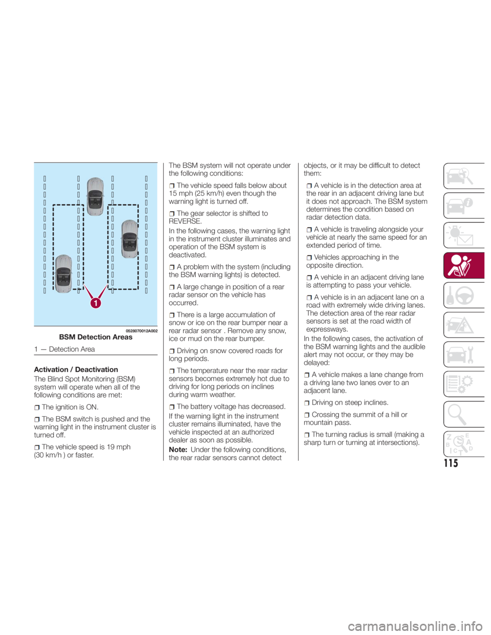
Activation / Deactivation
The Blind Spot Monitoring (BSM)
system will operate when all of the
following conditions are met:
The ignition is ON.
The BSM switch is pushed and the
warning light in the instrument cluster is
turned off.
The vehicle speed is 19 mph
(30km/h)orfaster. The BSM system will not operate under
the following conditions:
The vehicle speed falls below about
15 mph (25 km/h) even though the
warning light is turned off.
The gear selector is shifted to
REVERSE.
In the following cases, the warning light
in the instrument cluster illuminates and
operation of the BSM system is
deactivated.
A problem with the system (including
the BSM warning lights) is detected.
A large change in position of a rear
radar sensor on the vehicle has
occurred.
There is a large accumulation of
snow or ice on the rear bumper near a
rear radar sensor . Remove any snow,
ice or mud on the rear bumper.
Driving on snow covered roads for
long periods.
The temperature near the rear radar
sensors becomes extremely hot due to
driving for long periods on inclines
during warm weather.
The battery voltage has decreased.
If the warning light in the instrument
cluster remains illuminated, have the
vehicle inspected at an authorized
dealer as soon as possible.
Note: Under the following conditions,
the rear radar sensors cannot detect objects, or it may be difficult to detect
them:
A vehicle is in the detection area at
the rear in an adjacent driving lane but
it does not approach. The BSM system
determines the condition based on
radar detection data.
A vehicle is traveling alongside your
vehicle at nearly the same speed for an
extended period of time.
Vehicles approaching in the
opposite direction.
A vehicle in an adjacent driving lane
is attempting to pass your vehicle.
A vehicle is in an adjacent lane on a
road with extremely wide driving lanes.
The detection area of the rear radar
sensors is set at the road width of
expressways.
In the following cases, the activation of
the BSM warning lights and the audible
alert may not occur, or they may be
delayed:
A vehicle makes a lane change from
a driving lane two lanes over to an
adjacent lane.
Driving on steep inclines.
Crossing the summit of a hill or
mountain pass.
The turning radius is small (making a
sharp turn or turning at intersections).1 0528070012A002
BSM Detection Areas
1 — Detection Area
115
Page 118 of 292
Whenthereisadifferenceinthe
height between your driving lane and
the adjacent lane.
Immediately after pushing the BSM
switch and the system becomes
operable.
If the road width is extremely narrow,
vehicles two lanes over may be
detected. The detection area of the rear
radar sensors is set according to the
road width of expressways.
The BSM warning lights may turn on in
reaction to stationary objects on the
road or the roadside such as guardrails,
tunnels, sidewalls, and parked vehicles.
A BSM warning light may flash or the
audible alert may be activated several
times when making a turn at a city
intersection.
Turn off the BSM system while pulling a
trailer or while an accessory such as a
bicycle carrier is installed to the rear of
the vehicle. Otherwise, the radar’s
sound system waves will be blocked
causing the system to not operate
normally.
In the following cases, it may be difficult
to view the illumination/flashing of the
BSM warning lights equipped on the
door mirrors:
Snow or ice is adhering to the door
mirrors.
The door glass is fogged or covered
in snow, frost or dirt. The system switches to the Rear Cross
Traffic Alert function when the gear
selector is shifted to the REVERSE
position.
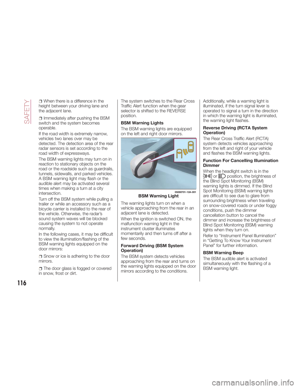
BSM Warning Lights
The BSM warning lights are equipped
on the left and right door mirrors.
The warning lights turn on when a
vehicle approaching from the rear in an
adjacent lane is detected.
When the ignition is switched ON, the
malfunction warning light in the
instrument cluster illuminates
momentarily and then turns off after a
few seconds.
Forward Driving (BSM System
Operation)
The BSM system detects vehicles
approaching from the rear and turns on
the warning lights equipped on the door
mirrors according to the conditions. Additionally, while a warning light is
illuminated, if the turn signal lever is
operated to signal a turn in the direction
in which the warning light is illuminated,
the warning light flashes.
Reverse Driving (RCTA System
Operation)
The Rear Cross Traffic Alert (RCTA)
system detects vehicles approaching
from the left and right of your vehicle
and flashes the BSM warning lights.
Function For Cancelling Illumination
Dimmer
When the headlight switch is in the
or position, the brightness of
the Blind Spot Monitoring (BSM)
warning lights is dimmed. If the Blind
Spot Monitoring (BSM) warning lights
are difficult to see due to glare from
surrounding brightness when traveling
on snow-covered roads or under foggy
conditions, push the dimmer
cancellation button to cancel the
dimmer and increase the brightness of
Blind Spot Monitoring (BSM) warning
lights when they turn on.
Refer to “Instrument Panel Illumination”
in “Getting To Know Your Instrument
Panel” for further information.
BSM Warning Beep
The BSM audible alert is activated
simultaneously with the flashing of a
BSM warning light. 05280701-12A-001
BSM Warning Light
116
SAFETY
Page 171 of 292
Looking At The Display
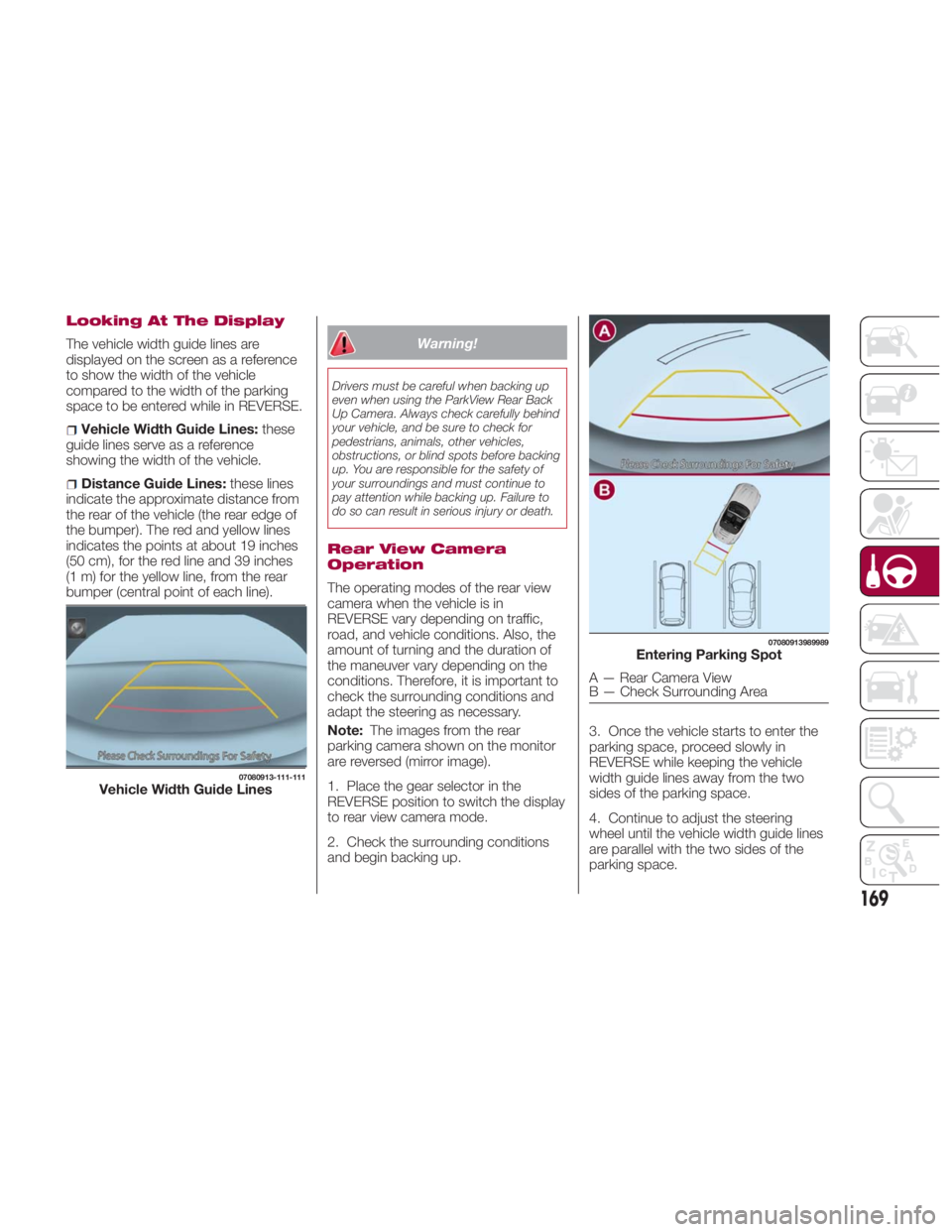
The vehicle width guide lines are
displayed on the screen as a reference
to show the width of the vehicle
compared to the width of the parking
space to be entered while in REVERSE.
Vehicle Width Guide Lines: these
guide lines serve as a reference
showing the width of the vehicle.
Distance Guide Lines: these lines
indicate the approximate distance from
the rear of the vehicle (the rear edge of
the bumper). The red and yellow lines
indicates the points at about 19 inches
(50 cm), for the red line and 39 inches
(1 m) for the yellow line, from the rear
bumper (central point of each line). Warning!Drivers must be careful when backing up
even when using the ParkView Rear Back
Up Camera. Always check carefully behind
your vehicle, and be sure to check for
pedestrians, animals, other vehicles,
obstructions, or blind spots before backing
up. You are responsible for the safety of
your surroundings and must continue to
pay attention while backing up. Failure to
do so can result in serious injury or death.
Rear View Camera
Operation
The operating modes of the rear view
camera when the vehicle is in
REVERSE vary depending on traffic,
road, and vehicle conditions. Also, the
amount of turning and the duration of
the maneuver vary depending on the
conditions. Therefore, it is important to
check the surrounding conditions and
adapt the steering as necessary.
Note: The images from the rear
parking camera shown on the monitor
are reversed (mirror image).
1. Place the gear selector in the
REVERSE position to switch the display
to rear view camera mode.
2. Check the surrounding conditions
and begin backing up. 3. Once the vehicle starts to enter the
parking space, proceed slowly in
REVERSE while keeping the vehicle
width guide lines away from the two
sides of the parking space.
4. Continue to adjust the steering
wheel until the vehicle width guide lines
are parallel with the two sides of the
parking space.07080913-111-111
Vehicle Width Guide Lines 07080913989989
Entering Parking Spot
A — Rear Camera View
B — Check Surrounding Area
169
Page 172 of 292
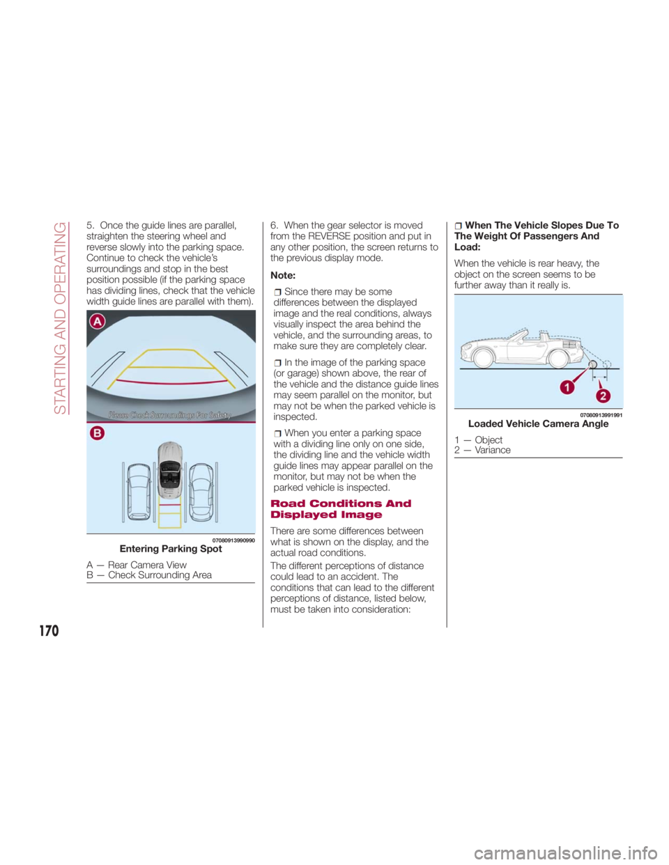
5. Once the guide lines are parallel,
straighten the steering wheel and
reverse slowly into the parking space.
Continue to check the vehicle’s
surroundings and stop in the best
position possible (if the parking space
has dividing lines, check that the vehicle
width guide lines are parallel with them). 6. When the gear selector is moved
from the REVERSE position and put in
any other position, the screen returns to
the previous display mode.
Note:
Since there may be some
differences between the displayed
image and the real conditions, always
visually inspect the area behind the
vehicle, and the surrounding areas, to
make sure they are completely clear.
In the image of the parking space
(or garage) shown above, the rear of
the vehicle and the distance guide lines
may seem parallel on the monitor, but
may not be when the parked vehicle is
inspected.
When you enter a parking space
with a dividing line only on one side,
the dividing line and the vehicle width
guide lines may appear parallel on the
monitor, but may not be when the
parked vehicle is inspected.
Road Conditions And
Displayed Image
There are some differences between
what is shown on the display, and the
actual road conditions.
The different perceptions of distance
could lead to an accident. The
conditions that can lead to the different
perceptions of distance, listed below,
must be taken into consideration: When The Vehicle Slopes Due To
The Weight Of Passengers And
Load:
When the vehicle is rear heavy, the
object on the screen seems to be
further away than it really is.07080913990990
Entering Parking Spot
A — Rear Camera View
B — Check Surrounding Area 07080913991991
Loaded Vehicle Camera Angle
1 — Object
2 — Variance
170
STARTING AND OPERATING
Page 240 of 292
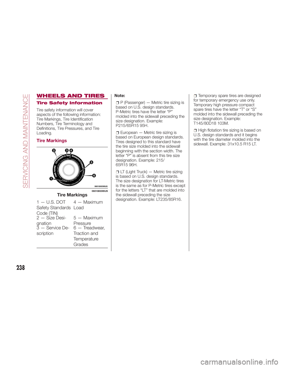
WHEELS AND TIRES Tire Safety Information
Tire safety information will cover
aspects of the following information:
Tire Markings, Tire Identification
Numbers, Tire Terminology and
Definitions, Tire Pressures, and Tire
Loading.
Tire Markings Note:
P (Passenger) — Metric tire sizing is
based on U.S. design standards.
P-Metric tires have the letter “P”
molded into the sidewall preceding the
size designation. Example:
P215/65R15 95H.
European — Metric tire sizing is
based on European design standards.
Tires designed to this standard have
the tire size molded into the sidewall
beginning with the section width. The
letter "P" is absent from this tire size
designation. Example: 215/
65R15 96H.
LT (Light Truck) — Metric tire sizing
is based on U.S. design standards.
The size designation for LT-Metric tires
is the same as for P-Metric tires except
for the letters “LT” that are molded into
the sidewall preceding the size
designation. Example: LT235/85R16. Temporary spare tires are designed
for temporary emergency use only.
Temporary high pressure compact
spare tires have the letter “T” or “S”
molded into the sidewall preceding the
size designation. Example:
T145/80D18 103M.
High flotation tire sizing is based on
U.S. design standards and it begins
with the tire diameter molded into the
sidewall. Example: 31x10.5 R15 LT.0601085395US
Tire Markings
1 — U.S. DOT
Safety Standards
Code (TIN) 4 — Maximum
Load
2 — Size Desi-
gnation 5 — Maximum
Pressure
3 — Service De-
scription 6 — Treadwear,
Traction and
Temperature
Grades
238
SERVICING AND MAINTENANCE
Page 241 of 292
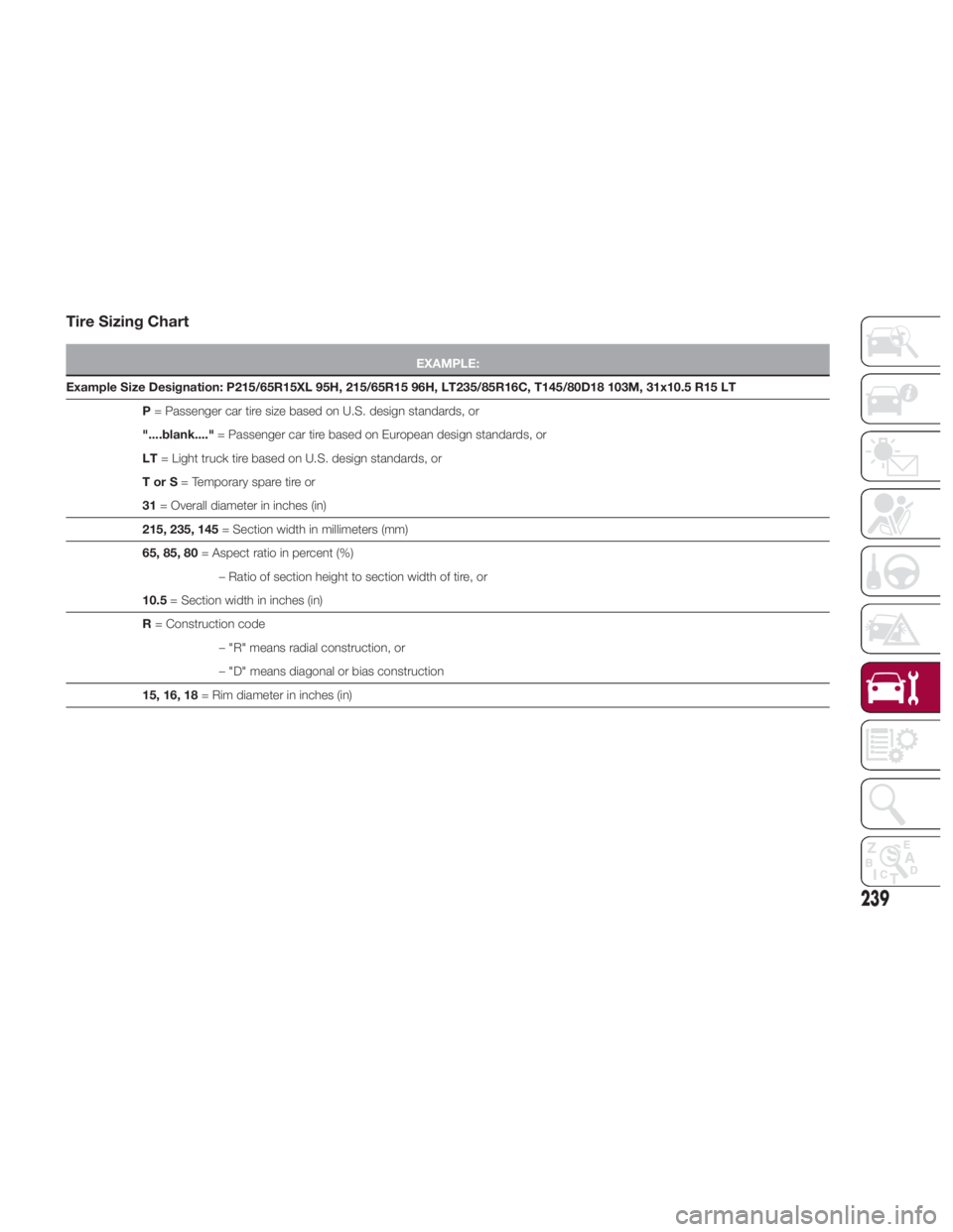
Tire Sizing Chart EXAMPLE:
Example Size Designation: P215/65R15XL 95H, 215/65R15 96H, LT235/85R16C, T145/80D18 103M, 31x10.5 R15 LT
P = Passenger
car tire size based on U.S. design standards, or
"....blank...." = Passenger car tire based on European design standards, or
LT = Light truck tire based on U.S. design standards, or
TorS = Temporary spare tire or
31 = Overall diameter in inches (in)
215, 235, 145 = Section width in millimeters (mm)
65, 85, 80 = Aspect ratio in percent (%)
– Ratio of section height to section width of tire, or
10.5 = Section width in inches (in)
R = Construction code
– "R" means radial construction, or
– "D" means diagonal or bias construction
15, 16, 18 = Rim diameter in inches (in)
239