mirror controls FIAT STILO 2006 1.G Owners Manual
[x] Cancel search | Manufacturer: FIAT, Model Year: 2006, Model line: STILO, Model: FIAT STILO 2006 1.GPages: 274, PDF Size: 4.76 MB
Page 5 of 274
4
SAFETY
DEVICES
CORRECT USE
OF THE CAR
WARNING
LIGHTS AND
MESSAGES
IN AN
EMERGENCY
CAR
MAINTENANCE
TECHNICAL
SPECIFICATIONS
INDEX
DASHBOARD
AND CONTROLSDASHBOARD ........................................................................ 5
INSTRUMENT PANEL ......................................................... 6
SYMBOLS ................................................................................. 8
THE FIAT CODE SYSTEM ................................................... 8
THE KEYS ................................................................................ 10
ALARM ..................................................................................... 17
IGNITION SWITCH.............................................................. 20
INSTRUMENTS ....................................................................... 21
MULTIFUNCTION DISPLAY ............................................. 23
TRIP COMPUTER ................................................................. 34
SEATS ........................................................................................ 37
HEAD RESTRAINTS .............................................................. 41
STEERING WHEEL ............................................................... 42
REARVIEW MIRRORS ........................................................... 43
HEATING/CLIMATE CONTROL SYSTEM .................... 44
HEATING AND VENTILATION ....................................... 46
MANUAL CLIMATE CONTROL SYSTEM .................... 48
AUTOMATIC TWO-ZONE
CLIMATE CONTROL SYSTEM ......................................... 51
EXTERNAL LIGHTS .............................................................. 57
WINDOW WASHING......................................................... 60CRUISE CONTROL ............................................................. 64
CEILING LIGHTS .................................................................. 67
CONTROLS ........................................................................... 68
INTERIOR FITTINGS ............................................................ 70
“SKYWINDOW”(BLADE SUNROOF) ........................... 74
DOORS .................................................................................... 79
POWER WINDOWS ........................................................... 80
BOOT ........................................................................................ 81
BONNET .................................................................................. 92
ROOF RACK/SKI RACK ..................................................... 93
HEADLIGHTS .......................................................................... 94
ABS SYSTEM ........................................................................... 95
ESP SYSTEM ............................................................................ 97
EOBD SYSTEM ....................................................................... 99
SOUND SYSTEM .................................................................... 100
ACCESSORIES PURCHASED BY THE OWNER ......... 101
“DUALDRIVE” ELECTRIC POWER
STEERING SYSTEM .............................................................. 102
PARKING SENSORS ............................................................ 103
AT THE FILLING STATION .............................................. 105
PROTECTING THE ENVIRONMENT ............................ 108
D D
A A
S S
H H
B B
O O
A A
R R
D D
A A
N N
D D
C C
O O
N N
T T
R R
O O
L L
S S
Page 44 of 274
43
SAFETY
DEVICES
CORRECT USE
OF THE CAR
WARNING
LIGHTS AND
MESSAGES
IN AN
EMERGENCY
CAR
MAINTENANCE
TECHNICAL
SPECIFICATIONS
INDEX
DASHBOARD
AND CONTROLS
REARVIEW MIRRORS
DRIVING MIRROR
The mirror is fitted with a safety device
that causes it to be released in the event
of a violent crash.
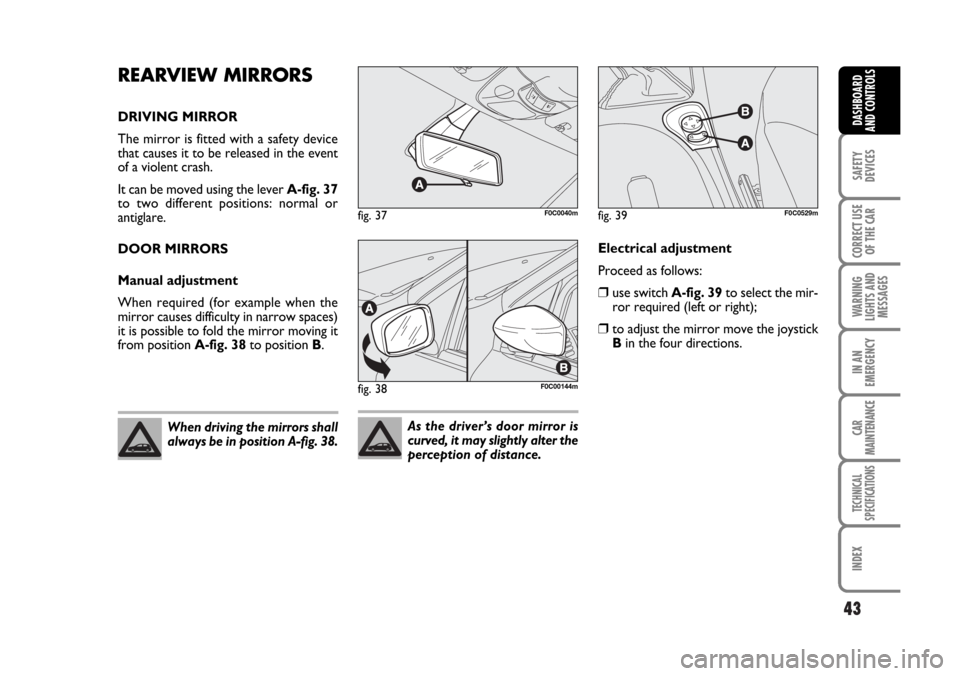
It can be moved using the lever A-fig. 37
to two different positions: normal or
antiglare.
DOOR MIRRORS
Manual adjustment
When required (for example when the
mirror causes difficulty in narrow spaces)
it is possible to fold the mirror moving it
from position A-fig. 38to position B.
fig. 37F0C0040m
fig. 38F0C00144m
When driving the mirrors shall
always be in position A-fig. 38.As the driver’s door mirror is
curved, it may slightly alter the
perception of distance.
Electrical adjustment
Proceed as follows:
❒use switch A-fig. 39to select the mir-
ror required (left or right);
❒to adjust the mirror move the joystick
Bin the four directions.
fig. 39F0C0529m
Page 48 of 274

47
SAFETY
DEVICES
CORRECT USE
OF THE CAR
WARNING
LIGHTS AND
MESSAGES
IN AN
EMERGENCY
CAR
MAINTENANCE
TECHNICAL
SPECIFICATIONS
INDEX
DASHBOARD
AND CONTROLS
FRONT WINDOW
FAST DEMISTING/DEFROSTING
Proceed as follows:
❒rotate completely (pointer on -)
knob Ato the right;
❒turn knob Cto -;
❒turn knob Eto -;
❒air recirculation off (button led Toff).
After demisting/defrosting use common
controls to maintain the optimum condi-
tions of visibility and comfort.
Window demisting
In the event of considerable outside mois-
ture and/or rain and/or considerable dif-
ferences in temperature inside and out-
side the passenger compartment, perform
the following preventive demisting proce-
dure:
❒air recirculation off (button led Toff);
❒turn knob Ato red section;
❒turn knob Cto 2ndspeed;
❒turn knob Eto -or to ≤if the win-
dows do not demist.HEATED REAR WINDOW
AND DOOR MIRROR
DEMISTING/DEFROSTING
Pressing button
(turns on this function
which is shown by the turning on of the
led on the button
(.
This function is timed and switches off au-
tomatically after 20 minutes. To cut out
this function press again button
(.
IMPORTANT Do not apply stickers on
the inside of the rear window over the
heating filaments to avoid damage that
might cause it to stop working properly.
FAN SPEED ADJUSTMENT
To ventilate the passenger’s compartment
properly, proceed as follows:
❒Central and side vents: completely
open;
❒Knob pointer Aon blue section;
❒knob pointer Con required speed;
❒Knob pointer Eto ¥;
❒air recirculation off (button led Toff).RECIRCULATION
Pressing button
Tturns on this func-
tion which is shown by the turning on of
the led on the button. This function is par-
ticularly useful when the outside air is
heavily polluted (in a traffic jam, tunnel,
etc.). However, it is better not to use it
for long periods, especially if there are sev-
eral people in the car.
IMPORTANT The inside air recirculation
system makes it possible to reach the re-
quired “heating” or “cooling” conditions
faster. Do not use the air recirculation
function on rainy/cold days as it would
considerably increase the possibility of the
windows misting inside.
Page 50 of 274

49
SAFETY
DEVICES
CORRECT USE
OF THE CAR
WARNING
LIGHTS AND
MESSAGES
IN AN
EMERGENCY
CAR
MAINTENANCE
TECHNICAL
SPECIFICATIONS
INDEX
DASHBOARD
AND CONTROLS
FRONT WINDOW
FAST DEMISTING/DEFROSTING
Proceed as follows:
❒press button ❄;
❒rotate completely (pointer on -)
knob Ato the right;
❒turn knob Cto -;
❒turn knob Fto -;
❒air recirculation off (button led Toff).
After demisting/defrosting use common
controls to maintain the optimum condi-
tions of visibility and comfort.
Window demisting
In the event of considerable outside mois-
ture and/or rain and/or considerable dif-
ferences in temperature inside and out-
side the passenger compartment, perform
the following preventive demisting proce-
dure:
❒press button ❄;
❒air recirculation off (button led Toff);
❒turn knob Ato red section;
❒turn knob Cto 2ndspeed;
❒turn knob Fto -or to ≤if the win-
dows do not demist.
Climate control system is very useful to
speed up demisting since it dehumidifies
the air. Set controls to demisting function
and switch on the climate control system
by pressing button
❄.
HEATED REAR WINDOW
AND DOOR MIRROR
DEMISTING/DEFROSTING
Pressing button
(turns on this function
which is shown by the turning on of the
led on the button
(.
This function is timed and switches off au-
tomatically after 20 minutes. To cut out
this function press again button
(.
IMPORTANT Do not apply stickers on
the inside of the rear window over the
heating filaments to avoid damage that
might cause it to stop working properly.FAN SPEED ADJUSTMENT
To ventilate the passenger’s compartment
properly, proceed as follows:
❒Central and side vents: completely
open;
❒Knob pointer Aon blue section;
❒knob pointer Con required speed;
❒Knob pointer Fto ¥;
❒air recirculation off (button led Toff).
Page 54 of 274

53
SAFETY
DEVICES
CORRECT USE
OF THE CAR
WARNING
LIGHTS AND
MESSAGES
IN AN
EMERGENCY
CAR
MAINTENANCE
TECHNICAL
SPECIFICATIONS
INDEX
DASHBOARD
AND CONTROLS
FAN SPEED ADJUSTMENT
To adjust the fan speed, press button
p.
The 12 selectable speeds are shown by the
lighting up of the bars on the climate con-
trol system display:
❒max fan speed = all bars lit
❒min fan speed = one bar lit.
The fan can be cut off (all bars off) only if
the climate control compressor has been
switched off pressing button
❄.
To restore automatic fan speed control,
after a manual adjustment, press button
AUTO.FAST FRONT WINDOW
DEMISTING/DEFROSTING
(MAX-DEF function)
Pressing button
-the climate control
automatically activates timed operation of
all the functions required to quicken
demisting/defrosting of the windscreen
and front side windows.
Functions are:
❒switches on climate control compres-
sor (if outside temperature exceeds
4°C);
❒switches off inside air recirculation, if
on (button led
Toff);
❒switches on heated rear window (but-
ton led
-on) and door mirror coils;
❒sets max air temperature;
❒activates proper air flow.HEATED REAR WINDOW
AND DOOR MIRROR
DEMISTING/DEFROSTING
Pressing button
(activates this function.
When this function is on, the button led
is on.
This function is timed.
IMPORTANT Press button
Tto ob-
tain outside air inlet into passenger com-
partment.
Page 62 of 274
61
SAFETY
DEVICES
CORRECT USE
OF THE CAR
WARNING
LIGHTS AND
MESSAGES
IN AN
EMERGENCY
CAR
MAINTENANCE
TECHNICAL
SPECIFICATIONS
INDEX
DASHBOARD
AND CONTROLS
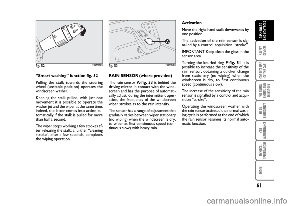
“Smart washing” function fig. 52
Pulling the stalk towards the steering
wheel (unstable position) operates the
windscreen washer.
Keeping the stalk pulled, with just one
movement it is possible to operate the
washer jet and the wiper at the same time;
indeed, the latter comes into action au-
tomatically if the stalk is pulled for more
than half a second.
The wiper stops working a few strokes af-
ter releasing the stalk; a further “cleaning
stroke”, after a few seconds, completes
the wiping operation.RAIN SENSOR (where provided)
The rain sensor A-fig. 53is behind the
driving mirror in contact with the wind-
screen and has the purpose of automati-
cally adjust, during the intermittent oper-
ation, the frequency of the windscreen
wiper strokes as to the rain intensity.
The sensor has a range of adjustment that
gradually varies between wiper stationary
(no wiping) when the windscreen is dry,
to wiper at first continuous speed (con-
tinuous slow) with heavy rain.Activation
Move the right-hand stalk downwards by
one position.
The activation of the rain sensor is sig-
nalled by a control acquisition “stroke”.
IMPORTANT Keep clean the glass in the
sensor area.
Turning the knurled ring F-fig. 51it is
possible to increase the sensitivity of the
rain sensor, obtaining a quicker change
from stationary (no wiping) when the
windscreen is dry, to first continuous
speed (continuous slow).
The increase of the sensitivity of the rain
sensor is signalled by a control and acqui-
sition “stroke”.
Operating the windscreen washer with
the rain sensor activated the normal wash-
ing cycle is performed at the end of which
the rain sensor resumes its normal auto-
matic function.
fig. 52F0C0049mfig. 53F0C0053m
Page 74 of 274
73
SAFETY
DEVICES
CORRECT USE
OF THE CAR
WARNING
LIGHTS AND
MESSAGES
IN AN
EMERGENCY
CAR
MAINTENANCE
TECHNICAL
SPECIFICATIONS
INDEX
DASHBOARD
AND CONTROLS
Resetting the shelf (after releasing)
Proceed as follows:
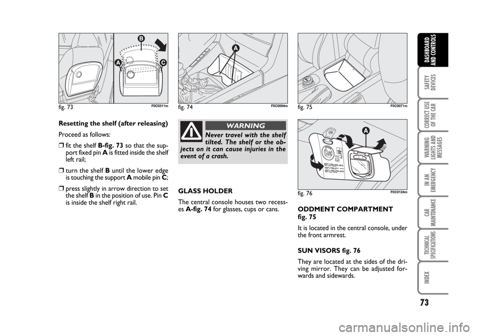
❒fit the shelf B-fig. 73so that the sup-
port fixed pin Ais fitted inside the shelf
left rail;
❒turn the shelf Buntil the lower edge
is touching the support Amobile pin C;
❒press slightly in arrow direction to set
the shelf Bin the position of use. Pin C
is inside the shelf right rail.GLASS HOLDER
The central console houses two recess-
es A-fig. 74for glasses, cups or cans.
ODDMENT COMPARTMENT
fig. 75
It is located in the central console, under
the front armrest.
SUN VISORS fig. 76
They are located at the sides of the dri-
ving mirror. They can be adjusted for-
wards and sidewards.
fig. 73F0C0311m
Never travel with the shelf
tilted. The shelf or the ob-
jects on it can cause injuries in the
event of a crash.
WARNING
fig. 74F0C0094mfig. 75F0C0071m
fig. 76F0C0124m
Page 75 of 274
74
SAFETY
DEVICES
CORRECT USE
OF THE CAR
WARNING
LIGHTS AND
MESSAGES
IN AN
EMERGENCY
CAR
MAINTENANCE
TECHNICAL
SPECIFICATIONS
INDEX
DASHBOARD
AND CONTROLS
On certain versions, th passenger’s sun vi-
sor is fitted, on the back, with a courtesy
mirror with a light which enables to use
the mirror also with poor sunlight.
Lift the lid Ato use the mirror.
When the ignition key is at STOP, the
light stays on for about 15 minutes: if in
this period a door or the tailgate is
opened, the light will stay on for another
15 minutes.
The passenger’s sun visor also carries the
symbols and the message concerning the
correct use of the child restraint system
with passenger’s air bag (for further in-
formation see paragraph “Front passen-
ger’s Air bag” in section “Safety”).“SKYWINDOW”
(BLADE SUNROOF)
(where provided)
This is a roof opening system consisting of
5 glass blades. The sunroof is equipped
with a sun curtain electronically con-
trolled, which has the function to prevent
sun radiation.
SUNROOF OPENING
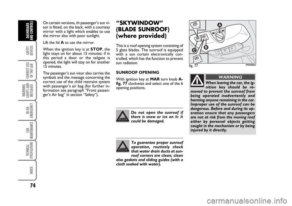
With ignition key at MARturn knob A-
fig. 77clockwise and select one of the 6
opening positions.
Do not open the sunroof if
there is snow or ice on it: it
could be damaged.
To guarantee proper sunroof
operation, routinely check
that water drain ducts at sun-
roof corners are clean; clean
also gaskets and sliding guides (with a
cloth soaked with water).
fig. 77F0C0222m
When leaving the car, the ig-
nition key should be re-
moved to prevent the sunroof from
being operated inadvertently and
harming anyone remaining in the car.
Improper use of the sunroof can be
dangerous. Before and during its op-
eration ensure that any passengers
are not at risk from the moving roof
either by personal objects getting
caught in the mechanism or by being
injured by it directly.
WARNING
Page 152 of 274
151
WARNING
LIGHTS AND
MESSAGES
IN AN
EMERGENCY
CAR
MAINTENANCE
TECHNICAL
SPECIFICATIONS
INDEX
DASHBOARD
AND CONTROLS
SAFETY
DEVICES
CORRECT USE
OF THE CAR
TOWING TRAILERS
IMPORTANT NOTES
For towing caravans or trailers the car
must be fitted with a certified tow hook
and an adequate electric system. Installa-
tion should be carried out by specialised
personnel who release a special document
for circulation on the road.
Install any specific and/or additional rear-
view mirrors as specified by law.
Remember that when towing a trailer,
steep hills are harder to climb, the brak-
ing spaces increase and overtaking takes
longer depending on the overall weight.
Engage a low gear when driving downhill,
rather than constantly using the brake.The weight the trailer exerts on the car
tow hook reduces by the same amount
the actual car loading capacity. To make
sure the maximum towable weight is not
exceeded (given in the log book) account
should be taken of the fully laden trailer,
including accessories and personal be-
longings.
Do not exceed the speed limits of the
country you are driving in. In any case do
not exceed 100 km/h.INSTALLING THE TOW HOOK
The towing device should be fastened to
the body by specialised personnel ac-
cording to any additional and/or integra-
tive information supplied by the Manufac-
turer of the device.
The ABS system with which
the car may be fitted does
not control the trailer braking system.
Drive with extreme care on slippery
roadbeds.
WARNING
Under no circumstances
should the car brake system
be altered to control the trailer brake.
The trailer braking system must be
fully independent of the car hydraulic
system.
WARNING
Page 184 of 274
183
WARNING
LIGHTS AND
MESSAGES
CAR
MAINTENANCE
TECHNICAL
SPECIFICATIONS
INDEX
DASHBOARD
AND CONTROLS
SAFETY
DEVICES
CORRECT USE
OF THE CAR
IN AN
EMERGENCY
E
D
D
F
A
E
B
A
B
B
B
B
B
B
B
A
B
B
A
C
A
C
C
C
A
CH1
H7
H7
D2R
W5W
H1
PY21W
WY5W
P21W
W5W
P4/21W
P21/5W
P21W
R5W
P21W
W2,3W
P21W
P21W
W5W
C5W
W5W
C5W
C10W
C5W
W5W
C5W55W
55W
55W
35W
5W
55W
21W
5W
21W
5W
4W/21W
21W/5W
21W
5W
21W
2,3W
21W
21W
5W
5W
5W
5W
10W
5W
5W
5W
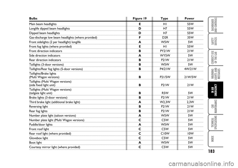
Bulbs Figure 19 Type Power
Main beam headlights
Longlife dipped beam headlights
Dipped beam headlights
Gas-discharge low beam headlights (where provided)
Front sidelights (2 per headlight) longlife
Front fog lights (where provided)
Front direction indicators
Side direction indicators
Rear direction indicators
Taillights (3-door versions)
Taillights/Rear fog lights (5-door versions)
Taillights/Brake lights
(Multi Wagon versions)
Taillights (Multi Wagon versions)
(side fixed light unit)
Taillights (Multi Wagon versions)
(tailgate light unit)
Brake lights (3-door versions)
Third brake light (additional brake light)
Reversing light
Rear fog lights
Number plate light (saloon versions)
Number plate light (Multi Wagon versions)
Puddle/door lights
Front roof light
Rear roof light (where provided)
Glovebox light
Boot light
Courtesy mirror light (where provided)