light FIAT STRADA 2011 Owner handbook (in English)
[x] Cancel search | Manufacturer: FIAT, Model Year: 2011, Model line: STRADA, Model: FIAT STRADA 2011Pages: 195, PDF Size: 3.68 MB
Page 128 of 195
126
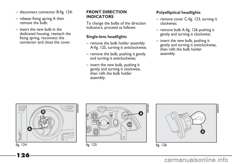
– disconnect connector B-fig. 124;
– release fixing spring A then
remove the bulb;
– insert the new bulb in the
dedicated housing, reattach the
fixing spring, reconnect the
connector and close the cover.FRONT DIRECTION
INDICATORS
To change the bulbs of the direction
indicators, proceed as follows:
Single-lens headlights
– remove the bulb holder assembly
A-fig. 125, turning it anticlockwise;
– remove the bulb, pushing it gently
and turning it anticlockwise;
– insert the new bulb, pushing it
gently and turning it clockwise,
then refit the bulb holder
assembly.Polyelliptical headlights
– remove cover C-fig. 123, turning it
clockwise;
– remove bulb A-fig. 126 pushing it
gently and turning it clockwise;
– insert the new bulb, pushing it
gently and turning it anticlockwise,
then refit the bulb holder
assembly.
fig. 126
F0X0107m
fig. 124
F0X0105m
fig. 125
F0X0106m
Page 129 of 195
127
FRONT SIDE LIGHTS
To change the bulbs of the side
lights, proceed as follows:
Single-lens headlights
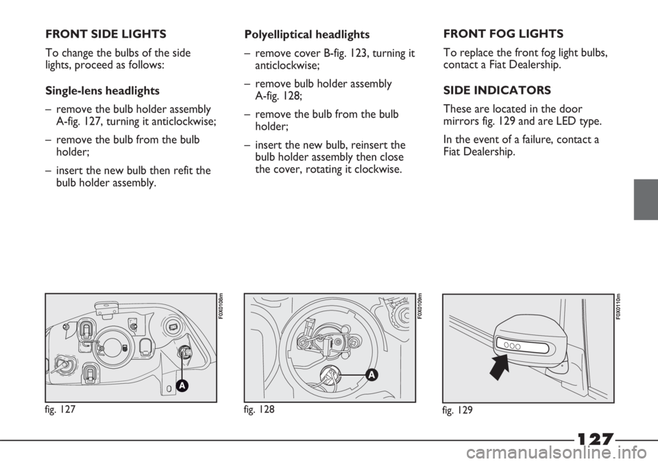
– remove the bulb holder assembly
A-fig. 127, turning it anticlockwise;
– remove the bulb from the bulb
holder;
– insert the new bulb then refit the
bulb holder assembly.Polyelliptical headlights
– remove cover B-fig. 123, turning it
anticlockwise;
– remove bulb holder assembly
A-fig. 128;
– remove the bulb from the bulb
holder;
– insert the new bulb, reinsert the
bulb holder assembly then close
the cover, rotating it clockwise.FRONT FOG LIGHTS
To replace the front fog light bulbs,
contact a Fiat Dealership.
SIDE INDICATORS
These are located in the door
mirrors fig. 129 and are LED type.
In the event of a failure, contact a
Fiat Dealership.
fig. 129
F0X0110m
fig. 127
F0X0108m
fig. 128
F0X0109m
Page 130 of 195
128
DRIVING LIGHTS
(Adventure version)
To replace the bulbs of the driving
lights, proceed as follows:
– steer the wheels inwards so that
you have a greater space in which
to work;
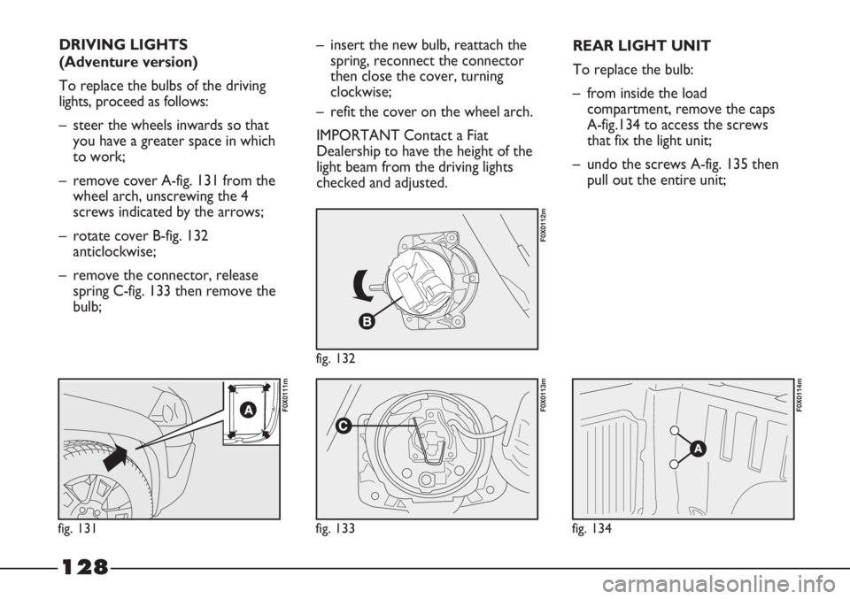
– remove cover A-fig. 131 from the
wheel arch, unscrewing the 4
screws indicated by the arrows;
– rotate cover B-fig. 132
anticlockwise;
– remove the connector, release
spring C-fig. 133 then remove the
bulb;
fig. 131
F0X0111m
fig. 132
F0X0112m
fig. 133
F0X0113m
fig. 134
F0X0114m
– insert the new bulb, reattach the
spring, reconnect the connector
then close the cover, turning
clockwise;
– refit the cover on the wheel arch.
IMPORTANT Contact a Fiat
Dealership to have the height of the
light beam from the driving lights
checked and adjusted.REAR LIGHT UNIT
To replace the bulb:
– from inside the load
compartment, remove the caps
A-fig.134 to access the screws
that fix the light unit;
– undo the screws A-fig. 135 then
pull out the entire unit;
Page 131 of 195

129
fig. 135
F0X0115m
fig. 136
F0X0116m
fig. 137
F0X0117m
– disconnect the connector then
undo the screws A-fig. 136 to
access the bulbs to be replaced;
– remove the bulbs, pushing them
slightly and turning them
anticlockwise;
The bulbs fig. 136 are:
B - 12V-P21/5W for the brake lights
C - 12V-P21W for the reversing
lights
D - 12V-P21W for the direction
indicators
E - 12V-P21/5W for the side lights
and rear fog lights.3rdBRAKE LIGHT
The third brake light is LED type.
In the event of a failure, contact a
Fiat Dealership.NUMBER PLATE LIGHT
fig. 137
To replace the bulb:
1) undo the fixing screws A and
remove the lens.
2) remove the bulb holder, rotating
it slightly, and replace press-fitted
bulb B.
Page 132 of 195
130
IF AN INTERNAL LIGHT
STOPS WORKING
FRONT ROOF LIGHT
With tilting lens
To replace the bulb:
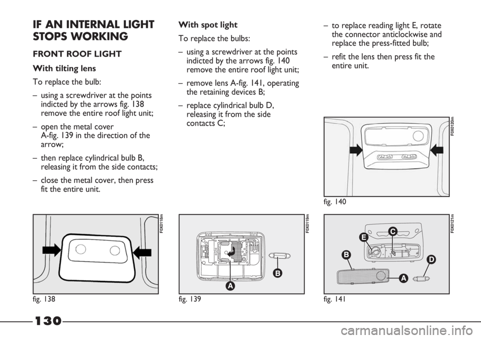
– using a screwdriver at the points
indicted by the arrows fig. 138
remove the entire roof light unit;
– open the metal cover
A-fig. 139 in the direction of the
arrow;
– then replace cylindrical bulb B,
releasing it from the side contacts;
– close the metal cover, then press
fit the entire unit.With spot light
To replace the bulbs:
– using a screwdriver at the points
indicted by the arrows fig. 140
remove the entire roof light unit;
– remove lens A-fig. 141, operating
the retaining devices B;
– replace cylindrical bulb D,
releasing it from the side
contacts C;– to replace reading light E, rotate
the connector anticlockwise and
replace the press-fitted bulb;
– refit the lens then press fit the
entire unit.
fig. 138
F0X0118m
fig. 139
F0X0119m
fig. 141
F0X0121m
fig. 140
F0X0120m
Page 133 of 195
131
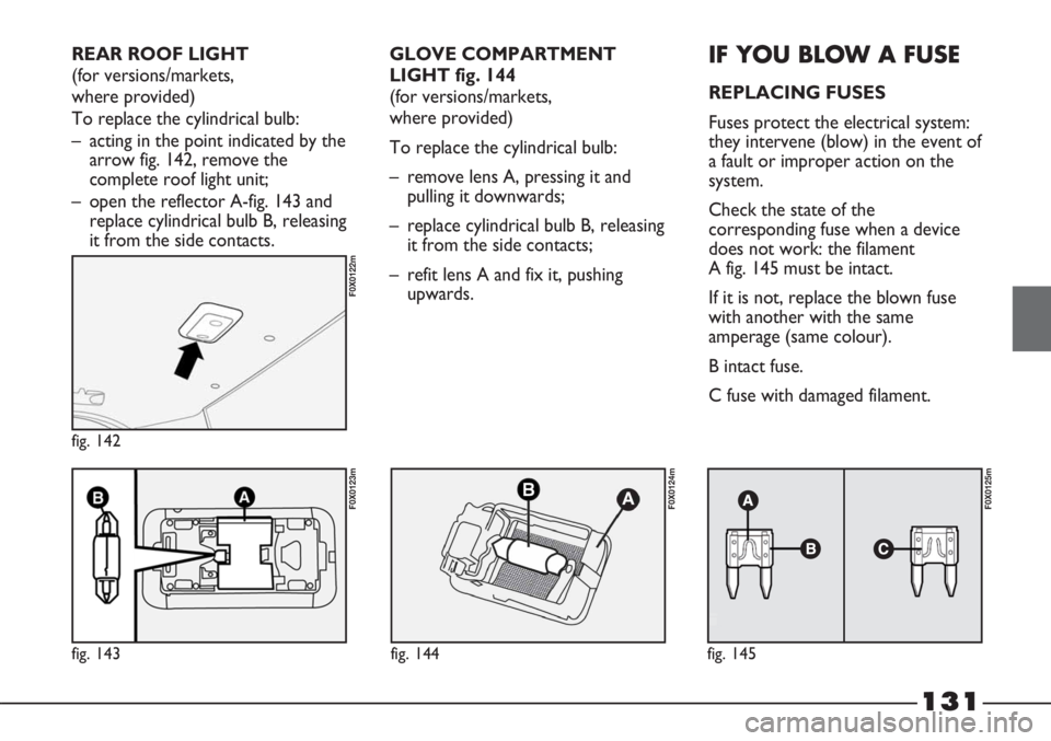
fig. 143
F0X0123m
fig. 142
F0X0122m
fig. 144
F0X0124m
fig. 145
F0X0125m
GLOVE COMPARTMENT
LIGHT fig. 144
(for versions/markets,
where provided)
To replace the cylindrical bulb:
– remove lens A, pressing it and
pulling it downwards;
– replace cylindrical bulb B, releasing
it from the side contacts;
– refit lens A and fix it, pushing
upwards.IF YOU BLOW A FUSE
REPLACING FUSES
Fuses protect the electrical system:
they intervene (blow) in the event of
a fault or improper action on the
system.
Check the state of the
corresponding fuse when a device
does not work: the filament
A fig. 145 must be intact.
If it is not, replace the blown fuse
with another with the same
amperage (same colour).
B intact fuse.
C fuse with damaged filament. REAR ROOF LIGHT
(for versions/markets,
where provided)
To replace the cylindrical bulb:
– acting in the point indicated by the
arrow fig. 142, remove the
complete roof light unit;
– open the reflector A-fig. 143 and
replace cylindrical bulb B, releasing
it from the side contacts.
Page 137 of 195
135
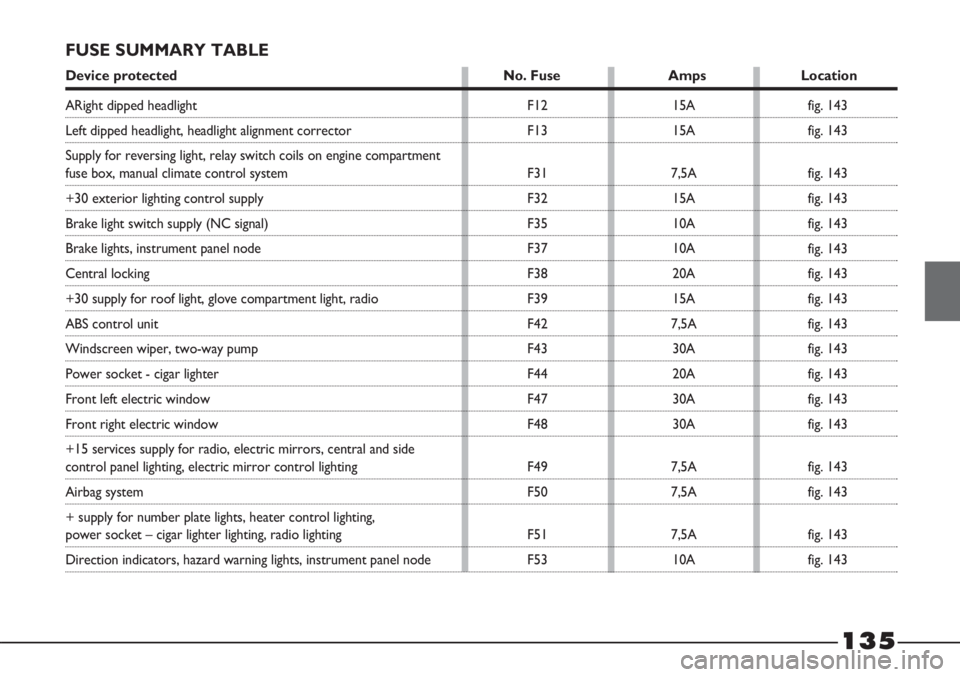
FUSE SUMMARY TABLE
Device protected No. Fuse Amps Location
F12
F13
F31
F32
F35
F37
F38
F39
F42
F43
F44
F47
F48
F49
F50
F51
F5315A
15A
7,5A
15A
10A
10A
20A
15A
7,5A
30A
20A
30A
30A
7,5A
7,5A
7,5A
10Afig. 143
fig. 143
fig. 143
fig. 143
fig. 143
fig. 143
fig. 143
fig. 143
fig. 143
fig. 143
fig. 143
fig. 143
fig. 143
fig. 143
fig. 143
fig. 143
fig. 143
ARight dipped headlight
Left dipped headlight, headlight alignment corrector
Supply for reversing light, relay switch coils on engine compartment
fuse box, manual climate control system
+30 exterior lighting control supply
Brake light switch supply (NC signal)
Brake lights, instrument panel node
Central locking
+30 supply for roof light, glove compartment light, radio
ABS control unit
Windscreen wiper, two-way pump
Power socket - cigar lighter
Front left electric window
Front right electric window
+15 services supply for radio, electric mirrors, central and side
control panel lighting, electric mirror control lighting
Airbag system
+ supply for number plate lights, heater control lighting,
power socket – cigar lighter lighting, radio lighting
Direction indicators, hazard warning lights, instrument panel node
Page 138 of 195
136
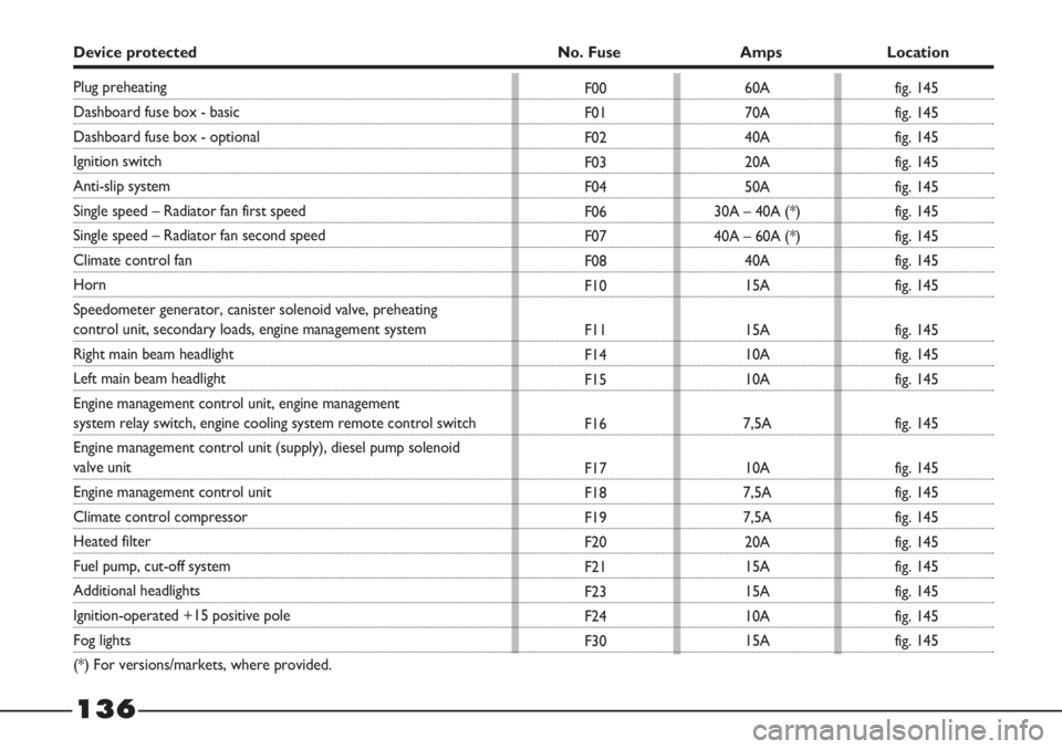
Device protected No. Fuse Amps Location
F00
F01
F02
F03
F04
F06
F07
F08
F10
F11
F14
F15
F16
F17
F18
F19
F20
F21
F23
F24
F3060A
70A
40A
20A
50A
30A – 40A (*)
40A – 60A (*)
40A
15A
15A
10A
10A
7,5A
10A
7,5A
7,5A
20A
15A
15A
10A
15A
Plug preheating
Dashboard fuse box - basic
Dashboard fuse box - optional
Ignition switch
Anti-slip system
Single speed – Radiator fan first speed
Single speed – Radiator fan second speed
Climate control fan
Horn
Speedometer generator, canister solenoid valve, preheating
control unit, secondary loads, engine management system
Right main beam headlight
Left main beam headlight
Engine management control unit, engine management
system relay switch, engine cooling system remote control switch
Engine management control unit (supply), diesel pump solenoid
valve unit
Engine management control unit
Climate control compressor
Heated filter
Fuel pump, cut-off system
Additional headlights
Ignition-operated +15 positive pole
Fog lights
(*) For versions/markets, where provided.fig. 145
fig. 145
fig. 145
fig. 145
fig. 145
fig. 145
fig. 145
fig. 145
fig. 145
fig. 145
fig. 145
fig. 145
fig. 145
fig. 145
fig. 145
fig. 145
fig. 145
fig. 145
fig. 145
fig. 145
fig. 145
Page 146 of 195
21 42 63 84 105
35 70 105 140 175
24 48 72 96 120
●●●●●
●●●●●
●●●●●
●●●●●
●●●●●
●●●●●
●●●●●
●●●●●
●●
144
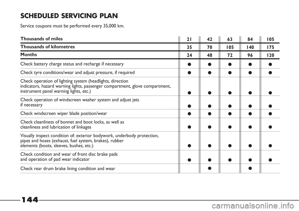
SCHEDULED SERVICING PLAN
Service coupons must be performed every 35,000 km.
Thousands of miles
Thousands of kilometres
Months
Check battery charge status and recharge if necessary
Check tyre conditions/wear and adjust pressure, if required
Check operation of lighting system (headlights, direction
indicators, hazard warning lights, passenger compartment, glove compartment,
instrument panel warning lights, etc.)
Check operation of windscreen washer system and adjust jets
if necessary
Check windscreen wiper blade position/wear
Check cleanliness of bonnet and boot locks, as well as
cleanliness and lubrication of linkages
Visually inspect condition of: exterior bodywork, underbody protection,
pipes and hoses (exhaust, fuel system, brakes), rubber
elements (boots, sleeves, bushes, etc.)
Check condition and wear of front disc brake pads
and operation of pad wear indicator
Check rear drum brake lining condition and wear
Page 148 of 195
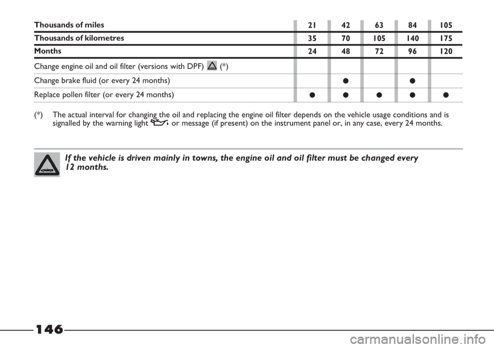
146
If the vehicle is driven mainly in towns, the engine oil and oil filter must be changed every
12 months.
21 42 63 84 105
35 70 105 140 175
24 48 72 96 120
●●
●●●●●
Thousands of miles
Thousands of kilometres
Months
Change engine oil and oil filter (versions with DPF) (*)
Change brake fluid (or every 24 months)
Replace pollen filter (or every 24 months)
(*) The actual interval for changing the oil and replacing the engine oil filter depends on the vehicle usage conditions and is
signalled by the warning light vor message (if present) on the instrument panel or, in any case, every 24 months.