warning light FIAT TALENTO 2017 Owner handbook (in English)
[x] Cancel search | Manufacturer: FIAT, Model Year: 2017, Model line: TALENTO, Model: FIAT TALENTO 2017Pages: 228, PDF Size: 4.47 MB
Page 128 of 228
This message is accompanied by the
STOPlight.
This means that at least one of the tyres
is punctured or is very deflated.
Replace it or contact a Fiat Dealership if
it is punctured. Re-inflate the tyre if it is
deflated.
Warning light 1 fig. 202 flashes for a few
seconds before remaining permanent
along with the message to that effect.
This message is accompanied by the
light.
They indicate that one of the tyres has
no sensors (for example the spare). In
all other cases, contact a Fiat
Dealership.
New regulations concerning tyre
pressure
The tyre pressure must be checked
when cold(see the label located on
the driver's door pillar). If tyre pressure
checking cannot be donecold,
increase the pressure 0.2-0.3 bar
(3 PSI).
Never deflate a hot tyre.
Spare tyre
If the vehicle has one, the spare tyre
has no sensors. When this is mounted
on the vehicle, warning light 1
fig. 202 flashes for a few seconds
before staying on together with the
warning light, while a dedicated
message is displayed on the instrument
panel.Spray can to repair the tyres and
inflation kit.
According to the valve specifics, only
use equipment approved by a Fiat
Dealership. Please see the paragraph
"Tyre kit" in the "Emergency" chapter.
IMPORTANT This function provides an
additional aid to the driver; however, it
cannot replace him. It does not exempt
you from ordinary driving safety or from
responsibility in case of an accident.
Check tyre pressure, including the
spare tyre, once a month.
IMPORTANT For the safety of the driver
and anyone else on board, you must
stop as soon as traffic conditions allow
when theSTOPwarning light turns on.
126
SAFETY
Page 130 of 228
ENGINE RUN-IN
Until you have gone 1,500 km, do not
exceed 130 km/h on the highest ratio,
or 2,500 rpm. After that mileage, you
can push the engine harder, but the
vehicle will perform better only after
having travelled 6,000 kilometres.
During the running-in period, do not
accelerate abruptly while the engine is
cold, and avoid running it too fast.
Coupon frequency:refer to the
"Scheduled Service Plan".
STARTING THE
ENGINE
138) 139) 140) 141) 142)
Vehicles with a key and remote
control
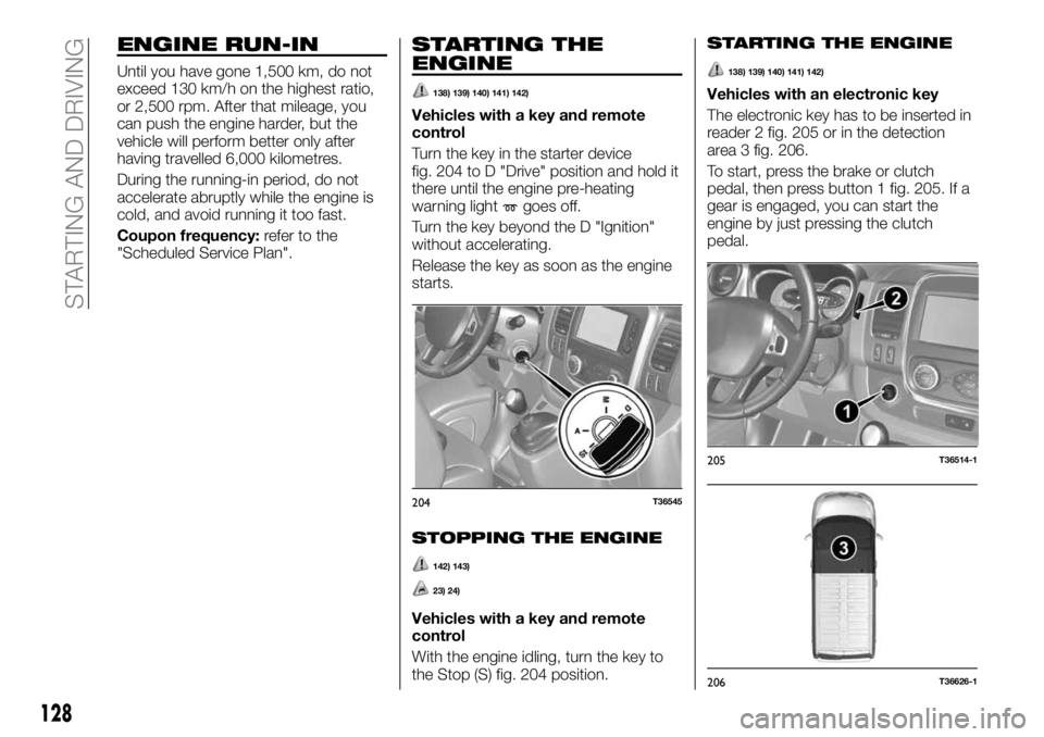
Turn the key in the starter device
fig. 204 to D "Drive" position and hold it
there until the engine pre-heating
warning light
goes off.
Turn the key beyond the D "Ignition"
without accelerating.
Release the key as soon as the engine
starts.
STOPPING THE ENGINE
142) 143)
23) 24)
Vehicles with a key and remote
control
With the engine idling, turn the key to
the Stop (S) fig. 204 position.
STARTING THE ENGINE
138) 139) 140) 141) 142)
Vehicles with an electronic key
The electronic key has to be inserted in
reader 2 fig. 205 or in the detection
area 3 fig. 206.
To start, press the brake or clutch
pedal, then press button 1 fig. 205. If a
gear is engaged, you can start the
engine by just pressing the clutch
pedal.
204T36545
205T36514-1
206T36626-1
128
STARTING AND DRIVING
Page 132 of 228
USING THE
GEARBOX
144)
25)
To engage reverse (vehicle
stopped)
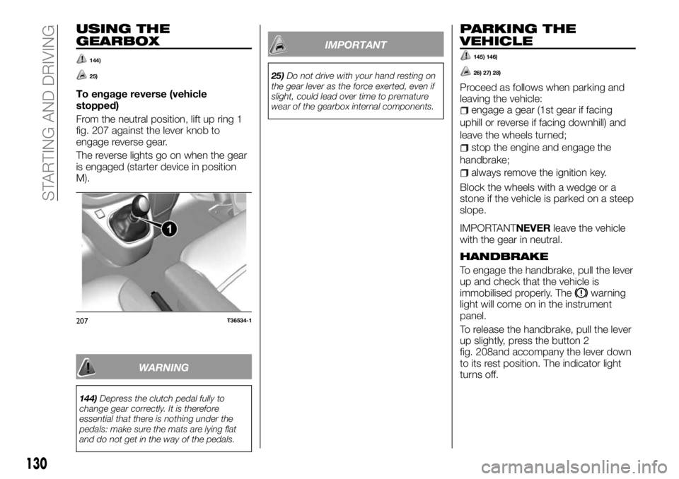
From the neutral position, lift up ring 1
fig. 207 against the lever knob to
engage reverse gear.
The reverse lights go on when the gear
is engaged (starter device in position
M).
WARNING
144)Depress the clutch pedal fully to
change gear correctly. It is therefore
essential that there is nothing under the
pedals: make sure the mats are lying flat
and do not get in the way of the pedals.
IMPORTANT
25)Do not drive with your hand resting on
the gear lever as the force exerted, even if
slight, could lead over time to premature
wear of the gearbox internal components.
PARKING THE
VEHICLE
145) 146)
26) 27) 28)
Proceed as follows when parking and
leaving the vehicle:
engage a gear (1st gear if facing
uphill or reverse if facing downhill) and
leave the wheels turned;
stop the engine and engage the
handbrake;
always remove the ignition key.
Block the wheels with a wedge or a
stone if the vehicle is parked on a steep
slope.
IMPORTANTNEVERleave the vehicle
with the gear in neutral.
HANDBRAKE
To engage the handbrake, pull the lever
up and check that the vehicle is
immobilised properly. The
warning
light will come on in the instrument
panel.
To release the handbrake, pull the lever
up slightly, press the button 2
fig. 208and accompany the lever down
to its rest position. The indicator light
turns off.
207T36534-1
130
STARTING AND DRIVING
Page 133 of 228
WARNING
145)Never leave children unattended in
the vehicle. In addition, always remove the
ignition key when leaving the vehicle and
take it out with you.
146)For cars equipped with a front
armrest, lift it up to ensure that it does not
interfere with the action of the handbrake.
IMPORTANT
26)Depending on the slope and/or load,
you may need to tighten the brake another
two clicks.
27)When driving, check that the handbrake
is completely lowered and disengaged (the
red light is off): you could overheat or
deteriorate it.28)Following a collision with a kerb, a high
step, a stone post or other types of urban
features, have your vehicle checked by the
Fiat Dealership to avoid any risk of
accident: you may have damaged an axle
shaft, the steering gear or other part.
INSTALLING THE
TOW HOOK
TO: 1,090 mm
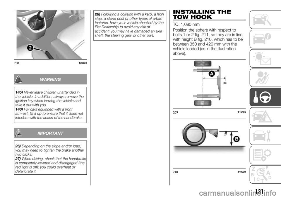
Position the sphere with respect to
bolts 1 or 2 fig. 211, so they are in line
with height B fig. 210, which has to be
between 350 and 420 mm with the
vehicle loaded (as in the illustration
above).
208T36534
209T19029
210T19030
131
Page 136 of 228
IMPORTANT In certain situations (for
example, a steep slope) the speed
limiter can be exceeded slightly,
because the device does not intervene
on the braking system.
WARNING
151)This function does not take the
driver's place. Nor does it allow the
vehicle's driving limits to be ignored,
encouraging faster driving. However, this
does not exempt the driver from normal
driving safety or from responsibility.
MINIMUM SPEED
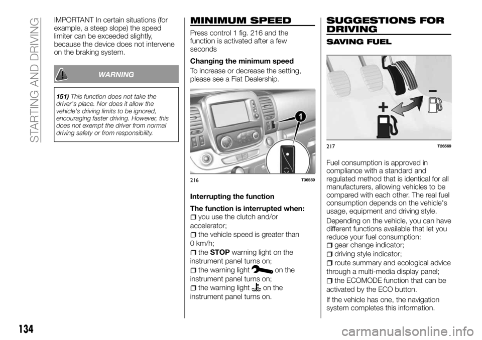
Press control 1 fig. 216 and the
function is activated after a few
seconds
Changing the minimum speed
To increase or decrease the setting,
please see a Fiat Dealership.
Interrupting the function
The function is interrupted when:
you use the clutch and/or
accelerator;
the vehicle speed is greater than
0 km/h;
theSTOPwarning light on the
instrument panel turns on;
the warning lighton the
instrument panel turns on;
the warning lighton the
instrument panel turns on.
SUGGESTIONS FOR
DRIVING
SAVING FUEL
Fuel consumption is approved in
compliance with a standard and
regulated method that is identical for all
manufacturers, allowing vehicles to be
compared with each other. The real fuel
consumption depends on the vehicle's
usage, equipment and driving style.
Depending on the vehicle, you can have
different functions available that let you
reduce your fuel consumption:
gear change indicator;
driving style indicator;
route summary and ecological advice
through a multi-media display panel;
the ECOMODE function that can be
activated by the ECO button.
If the vehicle has one, the navigation
system completes this information.
216T36559
217T26569
134
STARTING AND DRIVING
Page 137 of 228
Gear change indicators
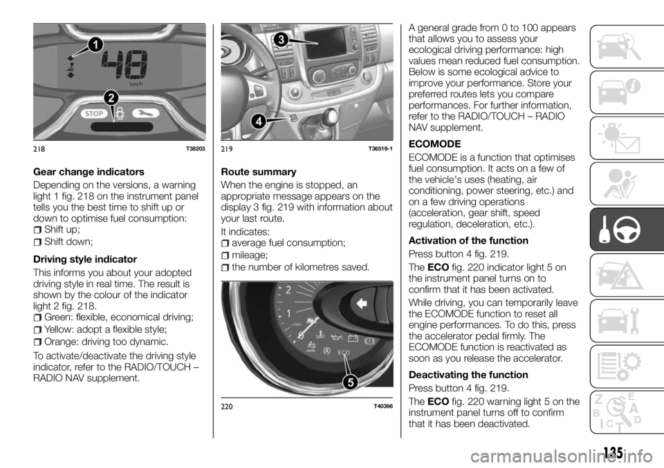
Depending on the versions, a warning
light 1 fig. 218 on the instrument panel
tells you the best time to shift up or
down to optimise fuel consumption:
Shift up;
Shift down;
Driving style indicator
This informs you about your adopted
driving style in real time. The result is
shown by the colour of the indicator
light 2 fig. 218.
Green: flexible, economical driving;
Yellow: adopt a flexible style;
Orange: driving too dynamic.
To activate/deactivate the driving style
indicator, refer to the RADIO/TOUCH –
RADIO NAV supplement.Route summary
When the engine is stopped, an
appropriate message appears on the
display 3 fig. 219 with information about
your last route.
It indicates:
average fuel consumption;
mileage;
the number of kilometres saved.A general grade from 0 to 100 appears
that allows you to assess your
ecological driving performance: high
values mean reduced fuel consumption.
Below is some ecological advice to
improve your performance. Store your
preferred routes lets you compare
performances. For further information,
refer to the RADIO/TOUCH – RADIO
NAV supplement.
ECOMODE
ECOMODE is a function that optimises
fuel consumption. It acts on a few of
the vehicle's uses (heating, air
conditioning, power steering, etc.) and
on a few driving operations
(acceleration, gear shift, speed
regulation, deceleration, etc.).
Activation of the function
Press button 4 fig. 219.
TheECOfig. 220 indicator light 5 on
the instrument panel turns on to
confirm that it has been activated.
While driving, you can temporarily leave
the ECOMODE function to reset all
engine performances. To do this, press
the accelerator pedal firmly. The
ECOMODE function is reactivated as
soon as you release the accelerator.
Deactivating the function
Press button 4 fig. 219.
TheECOfig. 220 warning light 5 on the
instrument panel turns off to confirm
that it has been deactivated.
218T38203219T36519-1
220T40396
135
Page 139 of 228
IN AN EMERGENCY
A punctured tyre or a burnt-out bulb?
At times, a problem may interfere with
our journey.
The pages on emergencies can help
you to deal with critical situations
independently and with calm.
In an emergency we recommend that
you call the toll free phone number
found in the Warranty Booklet.
It is also possible to call the national or
international universal freephone
number to search for the nearest Fiat
Dealership.HAZARD WARNING LIGHTS.....139
REPLACING AN INTERNAL BULB .139
REPLACING AN EXTERNAL BULB .140
PASSENGER COMPARTMENT
FUSES...................144
IN THE EVENT OF A PUNCTURE . .148
CHANGING A WHEEL.........148
TYRE INFLATION KIT..........151
JUMP STARTING............153
BATTERY RECHARGING.......154
TOWING THE VEHICLE........155
137
Page 140 of 228

HAZARD WARNING
LIGHTS
CONTROL
Press button 2 fig. 223. This
simultaneously activates the four
flashing arrows and those on the side. It
must be used only in case of danger to
warn other drivers that you have had to
stop in an unusual or prohibited place
or in special driving or traffic conditions.
Depending on the trim, in case you
stop abruptly, the emergency lights can
go on automatically. You can turn them
off by pressing the button 2
fig. 223 once.
REPLACING AN
INTERNAL BULB
152) 153) 154) 155)
Courtesy lights
Remove the lens from the courtesy light
concerned (1 fig. 224, 2 and 3 fig. 225,
6 and 7 fig. 226 ) using a screwdriver.
Pull the bulb downwards to remove
from its housing.
Type of bulb: W6W
Replace the bulb and reposition the
press-fit lens.
Vehicles with reading light
Type of bulb 2 fig. 227: pin type, 10W
Type of reading light bulb 3 fig. 227:
W5W
223T36520
224T36566
225T36567
226T36631
227T38811
138
IN AN EMERGENCY
Page 141 of 228
Glove compartment light
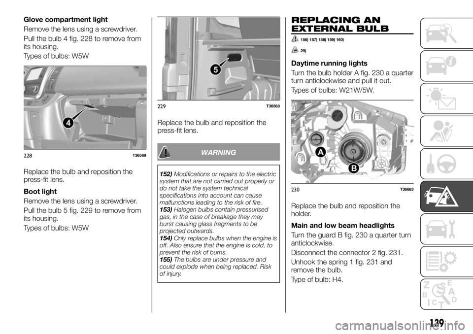
Remove the lens using a screwdriver.
Pull the bulb 4 fig. 228 to remove from
its housing.
Types of bulbs: W5W
Replace the bulb and reposition the
press-fit lens.
Boot light
Remove the lens using a screwdriver.
Pull the bulb 5 fig. 229 to remove from
its housing.
Types of bulbs: W5WReplace the bulb and reposition the
press-fit lens.
WARNING
152)Modifications or repairs to the electric
system that are not carried out properly or
do not take the system technical
specifications into account can cause
malfunctions leading to the risk of fire.
153)Halogen bulbs contain pressurised
gas, in the case of breakage they may
burst causing glass fragments to be
projected outwards.
154)Only replace bulbs when the engine is
off. Also ensure that the engine is cold, to
prevent the risk of burns.
155)The bulbs are under pressure and
could explode when being replaced. Risk
of injury.
REPLACING AN
EXTERNAL BULB
156) 157) 158) 159) 160)
29)
Daytime running lights
Turn the bulb holder A fig. 230 a quarter
turn anticlockwise and pull it out.
Types of bulbs: W21W/5W.
Replace the bulb and reposition the
holder.
Main and low beam headlights
Turn the guard B fig. 230 a quarter turn
anticlockwise.
Disconnect the connector 2 fig. 231.
Unhook the spring 1 fig. 231 and
remove the bulb.
Type of bulb: H4.
228T36569
229T36568
230T36663
139
Page 144 of 228
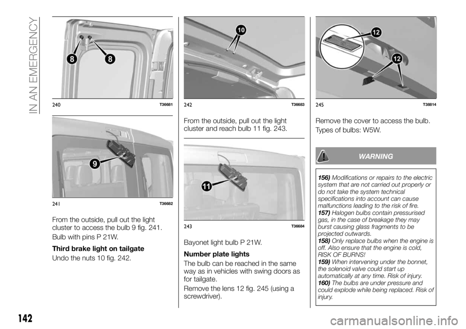
From the outside, pull out the light
cluster to access the bulb 9 fig. 241.
Bulb with pins P 21W.
Third brake light on tailgate
Undo the nuts 10 fig. 242.From the outside, pull out the light
cluster and reach bulb 11 fig. 243.
Bayonet light bulb P 21W.
Number plate lights
The bulb can be reached in the same
way as in vehicles with swing doors as
for tailgate.
Remove the lens 12 fig. 245 (using a
screwdriver).Remove the cover to access the bulb.
Types of bulbs: W5W.
WARNING
156)Modifications or repairs to the electric
system that are not carried out properly or
do not take the system technical
specifications into account can cause
malfunctions leading to the risk of fire.
157)Halogen bulbs contain pressurised
gas, in the case of breakage they may
burst causing glass fragments to be
projected outwards.
158)Only replace bulbs when the engine is
off. Also ensure that the engine is cold,
RISK OF BURNS!
159)When intervening under the bonnet,
the solenoid valve could start up
automatically at any time. Risk of injury.
160)The bulbs are under pressure and
could explode while being replaced. Risk of
injury.
240T36681
241T36682
242T36683
243T36684
245T38814
142
IN AN EMERGENCY