tow FIAT TALENTO 2020 Owner handbook (in English)
[x] Cancel search | Manufacturer: FIAT, Model Year: 2020, Model line: TALENTO, Model: FIAT TALENTO 2020Pages: 236, PDF Size: 4.86 MB
Page 23 of 236
Forgotten open door warning:ifa
door is open or not properly closed, as
soon as the vehicle has gone over
about 20 km/h, a message to this effect
will appear on the instrument panel
together with a warning light.
NOTE depending on the vehicle, the
accessories (radio, etc.) turn off when
the engine is stopped, on opening the
driver door or on closing the doors.
SLIDING SIDE DOOR
9) 10) 11)
Vehicles with remote control
The sliding side door locks and unlocks
by pressing the remote control button.
Vehicles with electronic key
The sliding side door locks and
unlocks:
by pressing the button on the
electronic key;
in easy access mode by
locking/unlocking the front doors or
tailgate.
Opening from outside
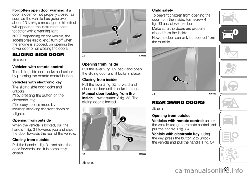
When the vehicle is locked, pull the
handle 1 fig. 31 towards you and slide
the door towards the rear of the vehicle.
Closing from outside
Pull the handle 1 fig. 31 and slide the
door forwards until it is completely
closed.Opening from inside
Pull the lever 2 fig. 32 back and open
the sliding door until it locks in place.
Closing from inside
Pull the lever 2 fig. 32 forward and
close the door until it locks in place.
Manual door locking from the
inside: Lower button 3 fig. 32. The
sliding door is locked.
12) 13)
Child safety
To prevent children from opening the
door from the inside, turn screw 4
fig. 33 and close the door.
Make sure the doors are properly
closed from the inside.
Now the door can only be opened from
the outside.
REAR SWING DOORS
14) 15)
Opening from outside
Vehicles with remote control: unlock
the vehicle using the remote control and
pull the handle 1 fig. 34.
Vehicle with electronic key: using
the key, press the button 2 to unlock
the vehicle and pull the handle 1 fig. 34.
31T36529
32T36530
33T36623
21
Page 30 of 236
To adjust the lumbar support, turn the
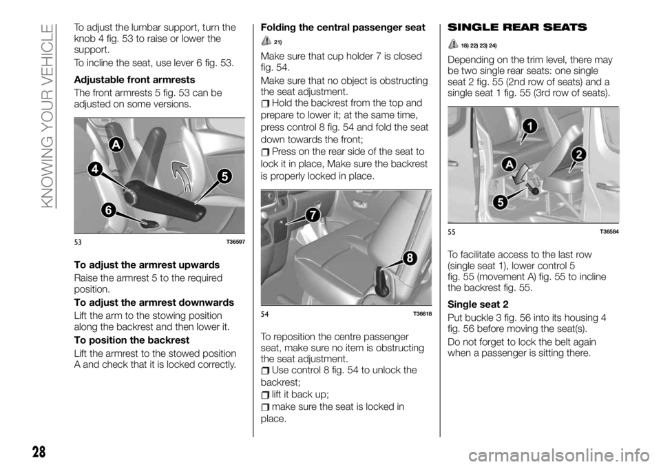
knob 4 fig. 53 to raise or lower the
support.
To incline the seat, use lever 6 fig. 53.
Adjustable front armrests
The front armrests 5 fig. 53 can be
adjusted on some versions.
To adjust the armrest upwards
Raise the armrest 5 to the required
position.
To adjust the armrest downwards
Lift the arm to the stowing position
along the backrest and then lower it.
To position the backrest
Lift the armrest to the stowed position
A and check that it is locked correctly.Folding the central passenger seat
21)
Make sure that cup holder 7 is closed
fig. 54.
Make sure that no object is obstructing
the seat adjustment.
Hold the backrest from the top and
prepare to lower it; at the same time,
press control 8 fig. 54 and fold the seat
down towards the front;
Press on the rear side of the seat to
lock it in place, Make sure the backrest
is properly locked in place.
To reposition the centre passenger
seat, make sure no item is obstructing
the seat adjustment.
Use control 8 fig. 54 to unlock the
backrest;
lift it back up;
make sure the seat is locked in
place.
SINGLE REAR SEATS
18) 22) 23) 24)
Depending on the trim level, there may
be two single rear seats: one single
seat 2 fig. 55 (2nd row of seats) and a
single seat 1 fig. 55 (3rd row of seats).
To facilitate access to the last row
(single seat 1), lower control 5
fig. 55 (movement A) fig. 55 to incline
the backrest fig. 55.
Single seat 2
Put buckle 3 fig. 56 into its housing 4
fig. 56 before moving the seat(s).
Do not forget to lock the belt again
when a passenger is sitting there.
A
4
5
6
53T36597
7
8
54T36618
55T36584
28
KNOWING YOUR VEHICLE
Page 32 of 236
Detachment
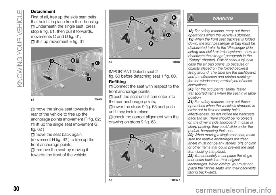
First of all, free up the side seat belts
that hold it in place from their housing.
Underneath the single seat, press
stop 9 fig. 61, then pull it forwards,
movements C and D fig. 61;
lift it up movement E fig. 61
move the single seat towards the
rear of the vehicle to free up the
anchorage points (movement F) fig. 62;
lift up the single seat (movement G
fig. 62 )
move the seat back again
(movement H fig. 62 ) to free up the
front anchorage points;
remove the seat by moving it
towards the front of the vehicle.IMPORTANT Detach seat 2
fig. 60 before detaching seat 1 fig. 60.
Refitting
Connect the seat with respect to the
front anchorage points;
push the seat until it can enter into
the rear anchorage points;
lower the stops 9 fig. 63 and push
until they lock in place;
check the correct alignment with the
drawing on stops 9 fig. 63.
WARNING
18)For safety reasons, carry out these
operations when the vehicle is stopped.
19)When the front seat backrest is folded
down, the front passenger airbag must be
deactivated (refer to the “Passenger side
airbag and child restraint systems – how to
deactivate the airbags” paragraph in the
“Safety” chapter). Risk of serious injury in
case the air bag opens up because of
objects placed on the folded backrest
flying around. The label (on the dashboard)
and the silkscreen and printed markings
(on the windscreen) remind you of these
instructions.
20)For the occupants' safety, fasten
transported items when the seat in in table
position.
21)For safety reasons, carry out these
operations when the vehicle is stopped. In
order not to limit the safety belt's
effectiveness, do not incline the backrests
back too far. There should be no objects
on the driver's side floorboard: in case of
sharp braking, they could slide under the
pedals, hampering their use.
22)When moving a single rear seat, make
sure the relative anchorages are clean
(there must not be any stones, bits of cloth
or other items that could prevent the seat
from locking into place).
23)You absolutely must place the single
rear seats back into their original
anchorages. When driving, you must not
place the "single seats with their backrests
facing backwards.
61T36659
62T36660
63T36660-1
30
KNOWING YOUR VEHICLE
Page 38 of 236
MAIN BEAM HEADLIGHTS
Ignition
When the engine is running and the
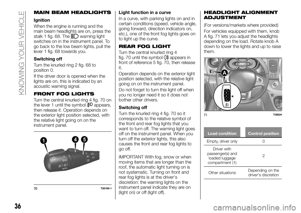
main beam headlights are on, press the
stalk 1 fig. 68. The
warning light
switches on in the instrument panel. To
go back to the low beam lights, pull the
lever 1 fig. 68 towards you.
Switching off
Turn the knurled ring 2 fig. 68 to
position 0.
If the driver door is opened when the
lights are on, this is indicated by an
acoustic warning signal.
FRONT FOG LIGHTS
Turn the central knurled ring 4 fig. 70 on
the lever 1 until the symbolappears,
then release it. Operation depends on
the exterior light position selected, with
the relative light going on on the
instrument panel.Light function in a curve
In a curve, with parking lights on and in
certain conditions (speed, vehicle angle,
going forward, direction indicators on,
etc.), one of the front fog lights goes on
to light up the curve.
REAR FOG LIGHT
Turn the central knurled ring 4
fig. 70 until the symbolappears in
front of reference 5 fig. 70, then release
it.
Operation depends on the exterior light
position selected, with the relative light
going on on the instrument panel.
Do not forget to turn this light off when
you no longer need it so it does not
bother other drivers.
Switching off
Turn the knurled ring 4 fig. 70 so it
corresponds to the relative symbol of
the front and rear fog lights that you
want to turn off. The warning light goes
off on the instrument panel. When you
turn off the exterior lights, this also
causes the front and rear fog lights to
go off.
IMPORTANT With fog, snow or when
moving items that are longer than the
roof, the automatic light turning on is
not systematic. Turning on front and
rear fog lights is at the driver's
discretion: the warning lights on the
instrument panel indicate they are on
(light on) or off (light off).
HEADLIGHT ALIGNMENT
ADJUSTMENT
(For versions/markets where provided)
For vehicles equipped with them, knob
A fig. 71 lets you adjust the headlights
depending on the load. Rotate knob A
down to lower the lights and up to raise
them.
Load condition Control position
Empty, driver only 0
Driver with
passenger(s) and
loaded
luggage
compartment (1)2
Other situationsDepending on the
driver's discretion
70T38199-1
71T36524
36
KNOWING YOUR VEHICLE
Page 39 of 236
IMPORTANT The table above contains
several examples. In all cases, adjust
the control A according to the vehicle
load to illuminate the road without
dazzling other drivers.
IMPORTANT If you are driving on the
left in a vehicle equipped for left hand
drive (or vice versa), you must adjust
the headlight orientation for the duration
of the visit.
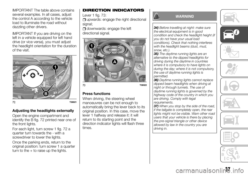
Adjusting the headlights externally
Open the engine compartment and
identify the B fig. 72 printed near one of
the front lights.
For each light, turn screw 1 fig. 72 a
quarter turn towards the - with a
screwdriver to lower the lights.
Once the parking ends, return to the
original position: turn screw 1 a quarter
turn to the + to raise up the lights.DIRECTION INDICATORS
Lever 1 fig. 73:upwards: engage the right directional
signal;
downwards: engage the left
directional signal.
Press functions
When driving, the steering wheel
manoeuvres can be not enough to
automatically bring the lever back to its
original position. In this case, move the
lever 1 halfway and release it: it will
return to its starting point and the
direction indicator lights will flash three
times.
WARNING
34)Before travelling at night: make sure
the electrical equipment is in good
condition and check the headlight height (if
you do not have your usual load
conditions). Check that nothing interferes
with the headlight beams (dust, mud,
snow, etc.).
35)The daytime running lights are an
alternative to the dipped headlights for
driving during the daytime in countries
where it is compulsory to have lights on
during the day; where it is not compulsory,
the use of daytime running lights is
permitted.
36)Daytime running lights cannot replace
dipped beam headlights when driving at
night or through tunnels. The use of
daytime running lights is governed by the
highway code of the country in which you
are driving. Comply with legal
requirements.
37)When you stop by the side of the road,
if the tailgate is completely open, the rear
lights might not be visible. Warn other road
users that your vehicle is there by placing
the pre-signal triangle or other device
allowed by law in the country you are
driving in.
72T38821
73T36522
37
Page 42 of 236
NOTE When driving, each time the
vehicle stops, the windscreen wipers
slow down: from fast to slow
continuous operation. As soon as the
vehicle moves again, the wipers return
to the initially selected speed. Any
operation of lever 1 fig. 81 takes
precedence and annuls any
automatism.
Cars with automatic windscreen
wipers
(For versions/markets where provided)
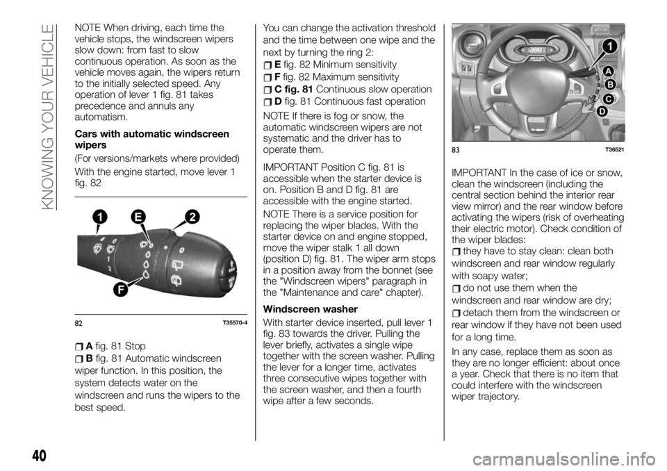
With the engine started, move lever 1
fig. 82
Afig. 81 Stop
Bfig. 81 Automatic windscreen
wiper function. In this position, the
system detects water on the
windscreen and runs the wipers to the
best speed.You can change the activation threshold
and the time between one wipe and the
next by turning the ring 2:
Efig. 82 Minimum sensitivity
Ffig. 82 Maximum sensitivity
C fig. 81Continuous slow operation
Dfig. 81 Continuous fast operation
NOTE If there is fog or snow, the
automatic windscreen wipers are not
systematic and the driver has to
operate them.
IMPORTANT Position C fig. 81 is
accessible when the starter device is
on. Position B and D fig. 81 are
accessible with the engine started.
NOTE There is a service position for
replacing the wiper blades. With the
starter device on and engine stopped,
move the wiper stalk 1 all down
(position D) fig. 81. The wiper arm stops
in a position away from the bonnet (see
the "Windscreen wipers" paragraph in
the "Maintenance and care" chapter).
Windscreen washer
With starter device inserted, pull lever 1
fig. 83 towards the driver. Pulling the
lever briefly, activates a single wipe
together with the screen washer. Pulling
the lever for a longer time, activates
three consecutive wipes together with
the screen washer, and then a fourth
wipe after a few seconds.IMPORTANT In the case of ice or snow,
clean the windscreen (including the
central section behind the interior rear
view mirror) and the rear window before
activating the wipers (risk of overheating
their electric motor). Check condition of
the wiper blades:
they have to stay clean: clean both
windscreen and rear window regularly
with soapy water;
do not use them when the
windscreen and rear window are dry;
detach them from the windscreen or
rear window if they have not been used
for a long time.
In any case, replace them as soon as
they are no longer efficient: about once
a year. Check that there is no item that
could interfere with the windscreen
wiper trajectory.
82T35570-4
83T36521
40
KNOWING YOUR VEHICLE
Page 47 of 236
IGNITION DEVICE
49) 50) 51) 52) 53)
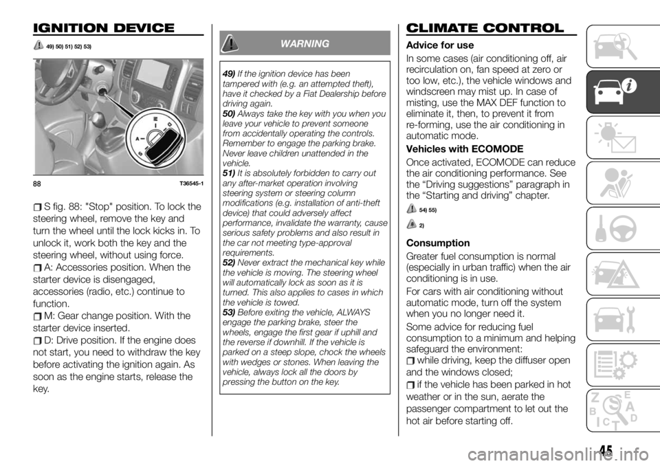
S fig. 88: "Stop" position. To lock the
steering wheel, remove the key and
turn the wheel until the lock kicks in. To
unlock it, work both the key and the
steering wheel, without using force.
A: Accessories position. When the
starter device is disengaged,
accessories (radio, etc.) continue to
function.
M: Gear change position. With the
starter device inserted.
D: Drive position. If the engine does
not start, you need to withdraw the key
before activating the ignition again. As
soon as the engine starts, release the
key.
WARNING
49)If the ignition device has been
tampered with (e.g. an attempted theft),
have it checked by a Fiat Dealership before
driving again.
50)Always take the key with you when you
leave your vehicle to prevent someone
from accidentally operating the controls.
Remember to engage the parking brake.
Never leave children unattended in the
vehicle.
51)It is absolutely forbidden to carry out
any after-market operation involving
steering system or steering column
modifications (e.g. installation of anti-theft
device) that could adversely affect
performance, invalidate the warranty, cause
serious safety problems and also result in
the car not meeting type-approval
requirements.
52)Never extract the mechanical key while
the vehicle is moving. The steering wheel
will automatically lock as soon as it is
turned. This also applies to cases in which
the vehicle is towed.
53)Before exiting the vehicle, ALWAYS
engage the parking brake, steer the
wheels, engage the first gear if uphill and
the reverse if downhill. If the vehicle is
parked on a steep slope, chock the wheels
with wedges or stones. When leaving the
vehicle, always lock all the doors by
pressing the button on the key.
CLIMATE CONTROL
Advice for use
In some cases (air conditioning off, air
recirculation on, fan speed at zero or
too low, etc.), the vehicle windows and
windscreen may mist up. In case of
misting, use the MAX DEF function to
eliminate it, then, to prevent it from
re-forming, use the air conditioning in
automatic mode.
Vehicles with ECOMODE
Once activated, ECOMODE can reduce
the air conditioning performance. See
the “Driving suggestions” paragraph in
the “Starting and driving” chapter.
54) 55)
2)
Consumption
Greater fuel consumption is normal
(especially in urban traffic) when the air
conditioning is in use.
For cars with air conditioning without
automatic mode, turn off the system
when you no longer need it.
Some advice for reducing fuel
consumption to a minimum and helping
safeguard the environment:
while driving, keep the diffuser open
and the windows closed;
if the vehicle has been parked in hot
weather or in the sun, aerate the
passenger compartment to let out the
hot air before starting off.
88T36545-1
45
Page 52 of 236
Air temperature adjustment
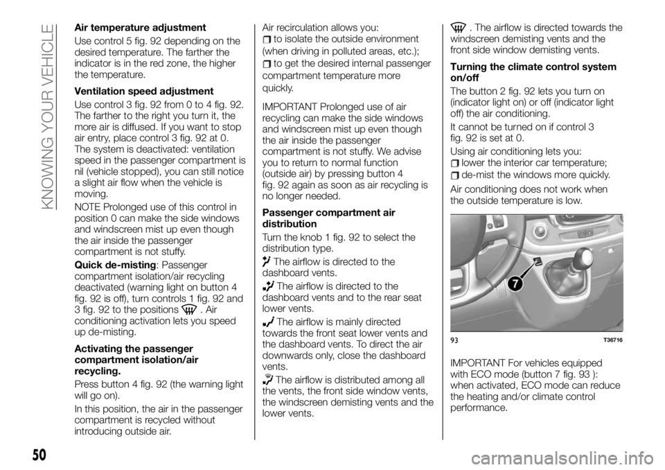
Use control 5 fig. 92 depending on the
desired temperature. The farther the
indicator is in the red zone, the higher
the temperature.
Ventilation speed adjustment
Use control 3 fig. 92 from 0 to 4 fig. 92.
The farther to the right you turn it, the
more air is diffused. If you want to stop
air entry, place control 3 fig. 92 at 0.
The system is deactivated: ventilation
speed in the passenger compartment is
nil (vehicle stopped), you can still notice
a slight air flow when the vehicle is
moving.
NOTE Prolonged use of this control in
position 0 can make the side windows
and windscreen mist up even though
the air inside the passenger
compartment is not stuffy.
Quick de-misting: Passenger
compartment isolation/air recycling
deactivated (warning light on button 4
fig. 92 is off), turn controls 1 fig. 92 and
3 fig. 92 to the positions
. Air
conditioning activation lets you speed
up de-misting.
Activating the passenger
compartment isolation/air
recycling.
Press button 4 fig. 92 (the warning light
will go on).
In this position, the air in the passenger
compartment is recycled without
introducing outside air.Air recirculation allows you:
to isolate the outside environment
(when driving in polluted areas, etc.);
to get the desired internal passenger
compartment temperature more
quickly.
IMPORTANT Prolonged use of air
recycling can make the side windows
and windscreen mist up even though
the air inside the passenger
compartment is not stuffy. We advise
you to return to normal function
(outside air) by pressing button 4
fig. 92 again as soon as air recycling is
no longer needed.
Passenger compartment air
distribution
Turn the knob 1 fig. 92 to select the
distribution type.
The airflow is directed to the
dashboard vents.
The airflow is directed to the
dashboard vents and to the rear seat
lower vents.
The airflow is mainly directed
towards the front seat lower vents and
the dashboard vents. To direct the air
downwards only, close the dashboard
vents.
The airflow is distributed among all
the vents, the front side window vents,
the windscreen demisting vents and the
lower vents.
. The airflow is directed towards the
windscreen demisting vents and the
front side window demisting vents.
Turning the climate control system
on/off
The button 2 fig. 92 lets you turn on
(indicator light on) or off (indicator light
off) the air conditioning.
It cannot be turned on if control 3
fig. 92 is set at 0.
Using air conditioning lets you:
lower the interior car temperature;
de-mist the windows more quickly.
Air conditioning does not work when
the outside temperature is low.
IMPORTANT For vehicles equipped
with ECO mode (button 7 fig. 93 ):
when activated, ECO mode can reduce
the heating and/or climate control
performance.
93T36716
50
KNOWING YOUR VEHICLE
Page 58 of 236
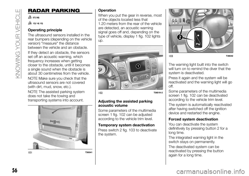
RADAR PARKING
57) 56)
13) 14) 15)
Operating principle
The ultrasound sensors installed in the
rear bumpers (depending on the vehicle
version) "measure" the distance
between the vehicle and an obstacle.
If they detect an obstacle, the sensors
set off an acoustic warning, which
frequency increases when getting
closer to the obstacle, until it becomes
a single sound when the obstacle is
about 30 centimetres from the vehicle.
NOTE Make sure you check that the
ultrasound sensors are not covered
(with dirt, mud, snow, etc.).
NOTE The assisted parking system
does not take the towing and
transporting systems into account.Operation
When you put the gear in reverse, most
of the objects located less that
1.20 meters from the rear of the vehicle
are detected, an acoustic warning
signal goes off and, depending on the
type of vehicle, display 1 fig. 102 lights
up.
Adjusting the assisted parking
acoustic volume
Some parameters of the multimedia
screen 1 fig. 102 can be adjusted
according to the vehicle trim level.
Temporary system deactivation
Press switch 2 fig. 103 to deactivate
the system.The warning light built into the switch
will turn on to remind the diver that the
system is deactivated.
Press it again and the system will be
reactivated and the warning light will go
off.
Some parameters of the multimedia
screen 1 fig. 102 can be deactivated
according to the vehicle trim level.
The system is automatically reactivated
after having switched off the ignition
device and restarted the engine.
Forced system deactivation
You can deactivate the system
definitively by pressing button 2 for a
long time.
The integrated warning light in the
switch stays on permanently.
The deactivated system can be
reactivated by pressing the button
again for a long time.
101T36541
102T36519-2
103T36542
56
KNOWING YOUR VEHICLE
Page 64 of 236
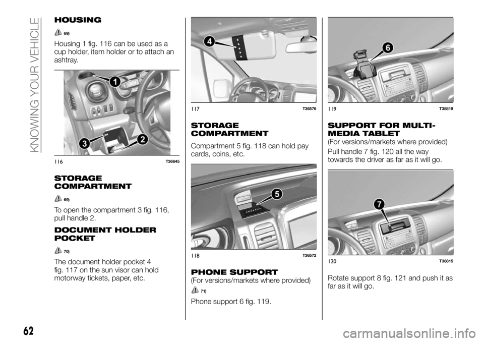
HOUSING
69)
Housing 1 fig. 116 can be used as a
cup holder, item holder or to attach an
ashtray.
STORAGE
COMPARTMENT
69)
To open the compartment 3 fig. 116,
pull handle 2.
DOCUMENT HOLDER
POCKET
70)
The document holder pocket 4
fig. 117 on the sun visor can hold
motorway tickets, paper, etc.
STORAGE
COMPARTMENT
Compartment 5 fig. 118 can hold pay
cards, coins, etc.
PHONE SUPPORT(For versions/markets where provided)
71)
Phone support 6 fig. 119.
SUPPORT FOR MULTI-
MEDIA TABLET
(For versions/markets where provided)
Pull handle 7 fig. 120 all the way
towards the driver as far as it will go.
Rotate support 8 fig. 121 and push it as
far as it will go.
116T36645
117T36576
118T36572
119T38819
120T38815
62
KNOWING YOUR VEHICLE