ECU FIAT TEMPRA 1988 Service And Repair Manual
[x] Cancel search | Manufacturer: FIAT, Model Year: 1988, Model line: TEMPRA, Model: FIAT TEMPRA 1988Pages: 171, PDF Size: 18.05 MB
Page 1 of 171
Please be sure to read the whole of this Chapter before carrying out any work on your car.
SAFETY FIRST!
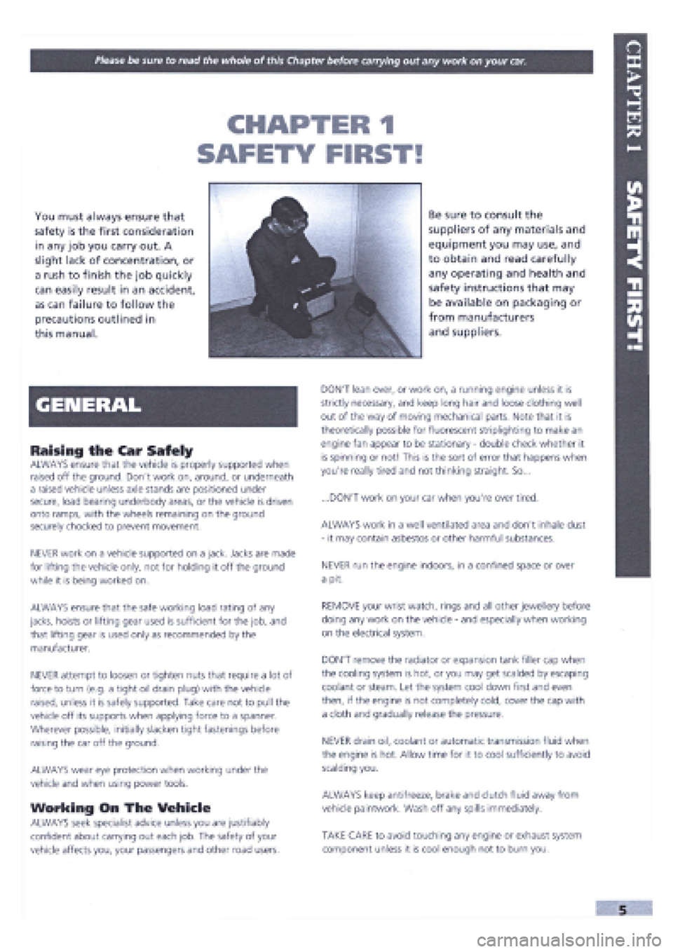
You must always ensure that
safety is the first consideration
in any job you carry out. A
slight lack of concentration, or
a rush to finish the job quickly
can easily result in an accident,
as can failure to follow the
precautions outlined in
this manual.
Be sure to consult the
suppliers of any materials and
equipment you may use, and
to obtain and read carefully
any operating and health and
safety instructions that may
be available on packaging or
from manufacturers
and suppliers.
Raising the Car Safely
ALWAYS ensure that the vehicle is properly supported when
raised off the ground. Don't work on, around, or underneath
a raised vehicle unless axle stands are positioned under
secure, load bearing underbody areas, or the vehicle is driven
onto ramps, with the wheels remaining on the ground
securely chocked to prevent movement.
NEVER work on a vehicle supported on a jack. Jacks are made
for lifting the vehicle only, not for holding it off the ground
while it is being worked on.
ALWAYS ensure that the safe working load rating of any
jacks, hoists or lifting gear used is sufficient for the job, and
that lifting gear is used only as recommended by the
manufacturer.
NEVER attempt to loosen or tighten nuts that require a lot of
force to turn (e.g. a tight oil drain plug) with the vehicle
raised, unless it is safely supported. Take care not to pull the
vehicle off its supports when applying force to a spanner.
Wherever possible, initially slacken tight fastenings before
raising the car off the ground.
ALWAYS wear eye protection when working under the
vehicle and when using power tools.
Working On The Vehicle
ALWAYS seek specialist advice unless you are justifiably
confident about carrying out each job. The safety of your
vehicle affects you, your passengers and other road users.
DON'T lean over, or work on, a running engine unless it is
strictly necessary, and keep long hair and loose clothing well
out of the way of moving mechanical parts. Note that it is
theoretically possible for fluorescent striplighting to make an
engine fan appear to be stationary
-
double check whether it
is spinning or not! This is the sort of error that happens when
you're really tired and not thinking straight. So...
...DON'T work on your car when you're over tired.
ALWAYS work in a well ventilated area and don't inhale dust
- it may contain asbestos or other harmful substances.
NEVER run the engine indoors, in a confined space or over
a pit.
REMOVE your wrist watch, rings and all other jewellery before
doing any work on the vehicle
-
and especially when working
on the electrical system.
DON'T remove the radiator or expansion tank filler cap when
the cooling system is hot, or you may get scalded by escaping
coolant or steam. Let the system cool down first and even
then, if the engine is not completely cold, cover the cap with
a cloth and gradually release the pressure.
NEVER drain oil, coolant or automatic transmission fluid when
the engine is hot. Allow time for it to cool sufficiently to avoid
scalding you.
ALWAYS keep antifreeze, brake and clutch fluid away from
vehicle paintwork. Wash off any spills immediately.
TAKE CARE to avoid touching any engine or exhaust system
component unless it is cool enough not to burn you.
Page 4 of 171
and explosions. Do not allow resin or 2-pack adhesive hardener,
or that supplied with filler or 2-pack stopper, to come into
contact with skin or eyes. Read carefully the safety notes
supplied on the can, tube or packaging and always wear
impervious gloves and goggles when working with them.
Fluoroelastomers
Fluoroelastomers are commonly used for oil seals, wiring and
cabling, bearing surfaces, gaskets, diaphragms, hoses and '0'
rings. If they are subjected to temperatures greater than 315
degrees C, they will decompose and can be potentially
hazardous. Some decomposition may occur at temperatures
above 200 degrees C, and it is obvious that when a car has
been in a fire or has been dismantled with the assistance of a
cutting torch or blow torch, the fluoroelastomers can
decompose in the manner indicated above.
According to the Health and Safety Executive, "Skin contact
with this liquid or decomposition residues can cause painful and
penetrating burns. Permanent irreversible skin and tissue
damage can occur". Damage can also be caused to eyes or by
the inhalation of fumes created as fluoroelastomers are burned
or heated.
After a vehicle has been exposed to fire or high temperatures:
1. Do not touch blackened or charred seals or equipment.
2. Preferably, don't handle parts containing decomposed
fluoroelastomers, but if you must, wear goggles and PVC
(polyvinyl chloride) or neoprene protective gloves whilst doing
so. Never handle such parts unless they are completely cool.
3. Contaminated parts, residues, materials and clothing,
including protective clothing and gloves, should be disposed of
by an approved contractor to landfill or by incineration
according to national or local regulations. Oil seals, gaskets and
'0' rings, along with contaminated material, must not
be burned.
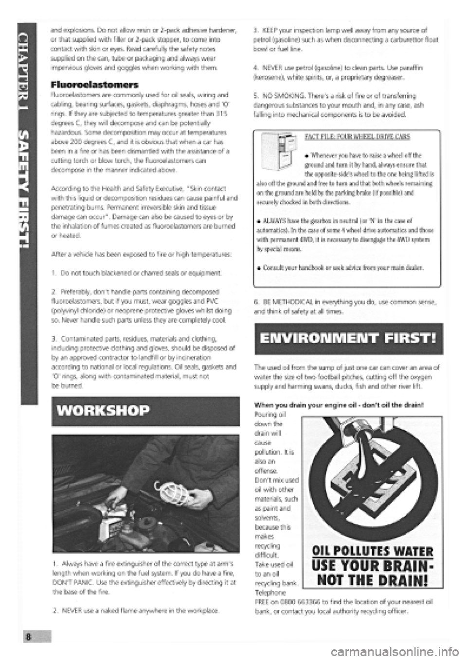
1. Always have a fire extinguisher of the correct type at arm's
length when working on the fuel system. If you do have a fire,
DON'T PANIC. Use the extinguisher effectively by directing it at
the base of the fire.
2. NEVER use a naked flame anywhere in the workplace.
3. KEEP your inspection lamp well away from any source of
petrol (gasoline) such as when disconnecting a carburettor float
bowl or fuel line.
4. NEVER use petrol (gasoline) to clean parts. Use paraffin
(kerosene), white spirits, or, a proprietary degreaser.
5. NO SMOKING. There's a risk of fire or of transferring
dangerous substances to your mouth and, in any case, ash
falling into mechanical components is to be avoided.
FACT FILE: FOUR WHEEL DRIVE CARS
• Whenever you have to raise a wheel off the
ground and turn it by hand, always ensure that
the opposite-side's wheel to the one being lifted is
also off the ground and free to turn and that both wheels remaining
on the ground are held by the parking brake (if possible) and
securely chocked in both directions.
• ALWAYS have the gearbox in neutral (or 'N' in the case of
automatics). In the case of
some
4 wheel drive automatics and those
with permanent 4WD, it is necessary to disengage the 4WD system
by special means.
• Consult your handbook or seek advice from your main dealer.
6. BE METHODICAL in everything you do, use common sense,
and think of safety at all times.
ENVIRONMENT FIRST!
The used oil from the sump of
just
one car
can
cover
an
area of
water the size of two football pitches, cutting off the oxygen
supply
and
harming swans, ducks, fish and other river lift.
When you drain your engine oil
-
don't oil the drain!
Pouring oil
down the
drain will
cause
pollution. It is
also an
offense.
Don't mix used
oil with other
materials, such
as paint and
solvents,
because this
makes
recycling
difficult.
Take used oil
to an oil
recycling bank.
Telephone
FREE on 0800 663366 to find the location of your nearest oil
bank, or contact you local authority recycling officer.
OIL POLLUTES WATER
USE YOUR BRAIN-
NOT THE DRAIN!
Page 12 of 171
EMERGENCY STARTING
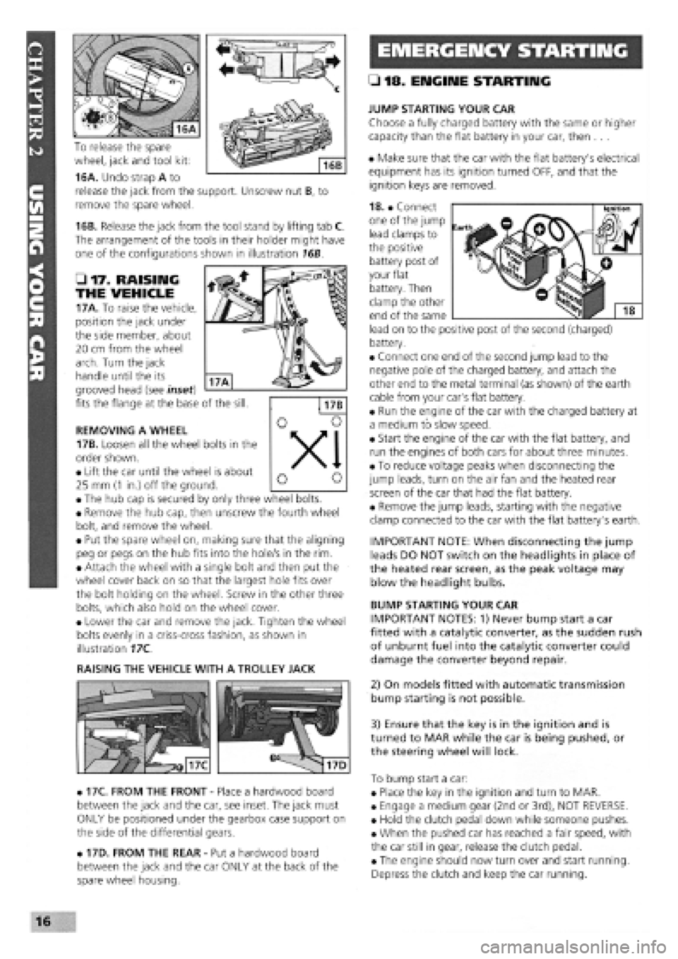
To release the spare
wheel, jack and tool kit:
16A. Undo strap A to
release the jack from the support. Unscrew nut B, to
remove the spare wheel.
16B. Release the jack from the tool stand by lifting tab C.
The arrangement of the tools in their holder might have
one of the configurations shown in illustration 16B.
• 17. RAISING
THE VEHICLE
17A. To raise the vehicle,
position the jack under
the side member, about
20 cm from the wheel
arch. Turn the jack
handle until the its
grooved head (see inset)
fits the flange at the base of the sill.
REMOVING A WHEEL
17B. Loosen all the wheel bolts in the
order shown.
• Lift the car until the wheel is about
25 mm
(1
in.) off the ground.
• The hub cap is secured by only three wheel bolts.
• Remove the hub cap, then unscrew the fourth wheel
bolt, and remove the wheel.
• Put the spare wheel on, making sure that the aligning
peg or pegs on the hub fits into the hole/s in the rim.
• Attach the wheel with a single bolt and then put the
wheel cover back on so that the largest hole fits over
the bolt holding on the wheel. Screw in the other three
bolts, which also hold on the wheel cover.
• Lower the car and remove the jack. Tighten the wheel
bolts evenly in a criss-cross fashion, as shown in
illustration 17C.
RAISING THE VEHICLE WITH A TROLLEY JACK
• 17C. FROM THE FRONT
-
Place a hardwood board
between the jack and the car, see inset. The jack must
ONLY be positioned under the gearbox case support on
the side of the differential gears.
• 17D. FROM THE REAR
-
Put a hardwood board
between the jack and the car ONLY at the back of the
spare wheel housing.
• 18. ENGINE STARTING
JUMP STARTING YOUR CAR
Choose a fully charged battery with the same or higher
capacity than the flat battery in your car, then ...
• Make sure that the car with the flat battery's electrical
equipment has its ignition turned OFF, and that the
ignition keys are removed.
18. • Connect
one of the jump
lead clamps to
the positive
battery post of
your flat
battery. Then
clamp the other
end of the same
lead on to the positive post of the second (charged)
battery.
• Connect one end of the second jump lead to the
negative pole of the charged battery, and attach the
other end to the metal terminal (as shown) of the earth
cable from your car's flat battery.
• Run the engine of the car with the charged battery at
a medium to slow speed.
• Start the engine of the car with the flat battery, and
run the engines of both cars for about three minutes.
• To reduce voltage peaks when disconnecting the
jump leads, turn on the air fan and the heated rear
screen of the car that had the flat battery.
• Remove the jump leads, starting with the negative
clamp connected to the car with the flat battery's earth.
IMPORTANT NOTE: When disconnecting the jump
leads DO NOT switch on the headlights in place of
the heated rear screen, as the peak voltage may
blow the headlight bulbs.
BUMP STARTING YOUR CAR
IMPORTANT NOTES: 1) Never bump start a car
fitted with a catalytic converter, as the sudden rush
of unburnt fuel into the catalytic converter could
damage the converter beyond repair.
2) On models fitted with automatic transmission
bump starting is not possible.
3) Ensure that the key is in the ignition and is
turned to MAR while the car is being pushed, or
the steering wheel will lock.
To bump start a car:
• Place the key in the ignition and turn to MAR.
• Engage a medium gear (2nd or 3rd), NOT REVERSE.
• Hold the clutch pedal down while someone pushes.
• When the pushed car has reached a fair speed, with
the car still in gear, release the clutch pedal.
• The engine should now turn over and start running.
Depress the clutch and keep the car running.
16
Page 24 of 171
Please read the whole of the CHAPTER 1, SAFETY FIRST! before carrying out any work on your car.
fUADTCSA I En Hr
GETTIIMG THROUGH THE MOT
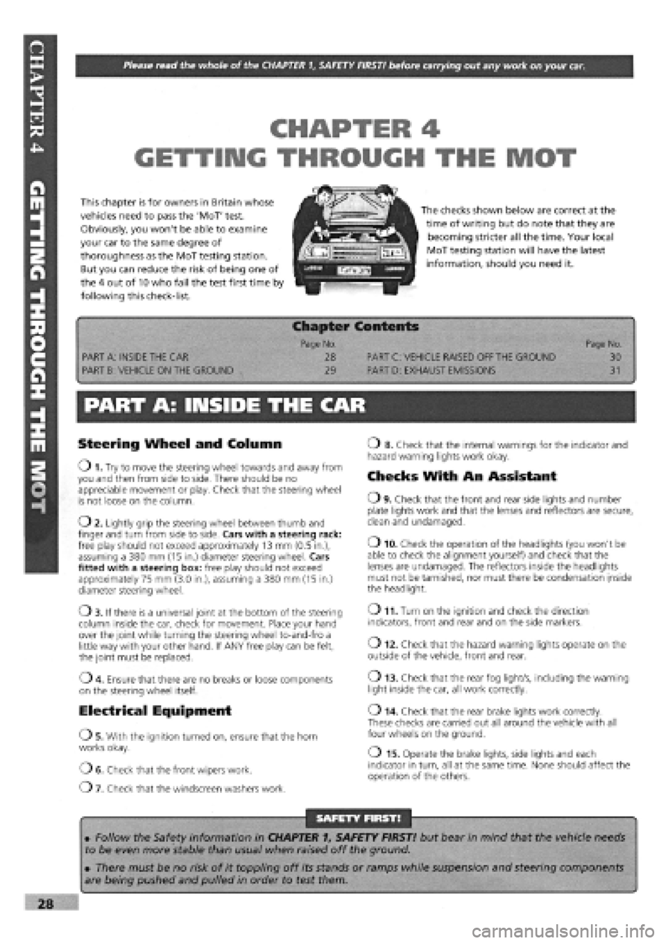
This chapter is for owners in Britain whose
vehicles need to pass the 'MoT' test.
Obviously, you won't be able to examine
your car to the same degree of
thoroughness as the MoT testing station.
But you can reduce the risk of being one of
the 4 out of 10 who fail the test first time by
following this check-list.
iMFTri
The checks shown below are correct at the
time of writing but do note that they are
becoming stricter all the time. Your local
MoT testing station will have the latest
information, should you need it.
1 p Chapter Contents -
Page No. Page No.
PART A: INSIDE THE CAR 28 PART C: VEHICLE RAISED OFF THE GROUND 30
PART B: VEHICLE ON THE GROUND 29 PART D: EXHAUST EMISSIONS 31
PART A: INSIDE THE CAR
Steering Wheel and Column
O 1. Try to move the steering wheel towards and away from you and then from side to side. There should be no appreciable movement or play. Check that the steering wheel is not loose on the column.
02 . Lightly grip the steering wheel between thumb and finger and turn from side to side. Cars with a steering rack: free play should not exceed approximately 13 mm (0.5 in.), assuming a 380 mm (15 in.) diameter steering wheel. Cars fitted with a steering box: free play should not exceed approximately 75 mm (3.0 in.), assuming a 380 mm (15 in.) diameter steering wheel.
Ob . If there is a universal joint at the bottom of the steering column inside the car, check for movement. Place your hand over the joint while turning the steering wheel to-and-fro a little way with your other hand. If ANY free play can be felt, the joint must be replaced.
04. Ensure that there are no breaks or loose components
on the steering wheel itself.
Electrical Equipment
OS . With the ignition turned on, ensure that the horn works okay.
OE . Check that the front wipers work.
07 . Check that the windscreen washers work.
o 8. Check that the internal warnings for the indicator and hazard warning lights work okay.
Checks With An Assistant
O9 . Check that the front and rear side lights and number plate lights work and that the lenses and reflectors are secure, clean and undamaged.
o 10. Check the operation of the headlights (you won't be able to check the alignment yourself) and check that the lenses are undamaged. The reflectors inside the headlights must not be tarnished, nor must there be condensation inside the headlight.
o 11. Turn on the ignition and check the direction
indicators, front and rear and on the side markers.
o 12. Check that the hazard warning lights operate on the
outside of the vehicle, front and rear.
o 13. Check that the rear fog light/s, including the warning
light inside the car, all work correctly.
o 14. Check that the rear brake lights work correctly. These checks are carried out all around the vehicle with all four wheels on the ground.
o 15. Operate the brake lights, side lights and each indicator in turn, all at the same time. None should affect the operation of the others.
SAFETY FIRST!
• Follow the Safety information in CHAPTER 1, SAFETY FIRST! but bear in mind that the vehicle needs
to be even more stable than usual when raised off the ground.
• There must be no risk of it toppling off its stands or ramps while suspension and steering components
are being pushed and pulled in order to test them.
Page 25 of 171
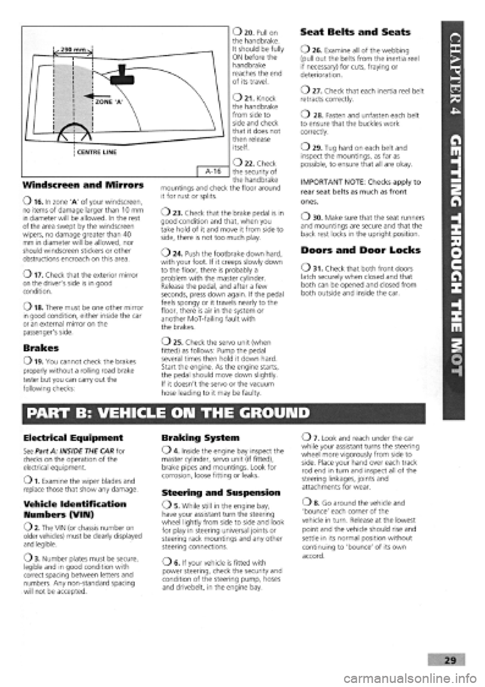
Windscreen and Mirrors
O 16. In zone 'A' of your windscreen, no items of damage larger than 10 mm in diameter will be allowed. In the rest of the area swept by the windscreen wipers, no damage greater than 40 mm in diameter will be allowed, nor should windscreen stickers or other obstructions encroach on this area.
o 17. Check that the exterior mirror on the driver's side is in good condition.
o 18. There must be one other mirror in good condition, either inside the car or an external mirror on the passenger's side.
Brakes
O 19. You cannot check the brakes
properly without a rolling road brake
tester but you can carry out the
following checks:
O 20. Pull on the handbrake. It should be fully ON before the handbrake reaches the end of its travel.
O 21. Knock the handbrake from side to side and check that it does not then release itself.
O 22. Check the security of the handbrake mountings and check the floor around it for rust or splits.
o 23. Check that the brake pedal is in good condition and that, when you take hold of it and move it from side to side, there is not too much play.
o 24. Push the footbrake down hard, with your foot. If it creeps slowly down to the floor, there is probably a problem with the master cylinder. Release the pedal, and after a few seconds, press down again. If the pedal feels spongy or it travels nearly to the floor, there is air in the system or another MoT-failing fault with the brakes.
o 25. Check the servo unit (when
fitted) as follows: Pump the pedal
several times then hold it down hard.
Start the engine. As the engine starts,
the pedal should move down slightly.
If it doesn't the servo or the vacuum
hose leading to it may be faulty.
Seat Belts and Seats
O 26. Examine all of the webbing (pull out the belts from the inertia reel if necessary) for cuts, fraying or deterioration.
o 27. Check that each inertia reel belt retracts correctly.
o 28. Fasten and unfasten each belt to ensure that the buckles work correctly.
o 29. Tug hard on each belt and inspect the mountings, as far as possible, to ensure that all are okay.
IMPORTANT NOTE: Checks apply to
rear seat belts as much as front
ones.
O 30. Make sure that the seat runners and mountings are secure and that the back rest locks in the upright position.
Doors and Door Locks
O 31. Check that both front doors latch securely when closed and that both can be opened and closed from both outside and inside the car.
PART B: VEHICLE ON THE GROUND
Electrical Equipment
See Part A: INSIDE THE CAR for checks on the operation of the electrical equipment.
O 1. Examine the wiper blades and replace those that show any damage.
Vehicle Identification
Numbers (VIIU)
O 2. The VIN (or chassis number on older vehicles) must be clearly displayed and legible.
O 3. Number plates must be secure, legible and in good condition with correct spacing between letters and numbers. Any non-standard spacing will not be accepted.
Braking System
O 4. Inside the engine bay inspect the master cylinder, servo unit (if fitted), brake pipes and mountings. Look for corrosion, loose fitting or leaks.
Steering and Suspension
OS . While still in the engine bay, have your assistant turn the steering wheel lightly from side to side and look for play in steering universal joints or steering rack mountings and any other steering connections.
OE. If your vehicle is fitted with power steering, check the security and condition of the steering pump, hoses and drivebelt, in the engine bay.
O 7. Look and reach under the car while your assistant turns the steering wheel more vigorously from side to side. Place your hand over each track rod end in turn and inspect all of the steering linkages, joints and attachments for wear.
o 8. Go around the vehicle and
'bounce' each corner of the
vehicle in turn. Release at the lowest
point and the vehicle should rise and
settle in its normal position without
continuing to 'bounce' of its own
accord.
Page 26 of 171
PART C: VEHICLE RAISED OFF THE GROUND
Bodywork Structure
01
.
Any sharp edges on the external bodywork, caused by damage or corrosion will cause the vehicle to fail.
02 . Check all load bearing areas for corrosion. Open the doors and check the sills inside and out, above and below. Any corrosion in structural metalwork within 30 cm (12 in.) of seat belt mounting, steering and suspension attachment points will cause the vehicle to fail.
Wheels and Tyres
Under the Front of the
Car
You will need to support the front of the car on axle stands with the rear wheels firmly chocked in both directions.
OE . Have your helper turn the steering from lock to lock and check that the steering turns smoothly and that the brake hoses or pipes do not contact the wheel, tyre or any part of the steering or suspension.
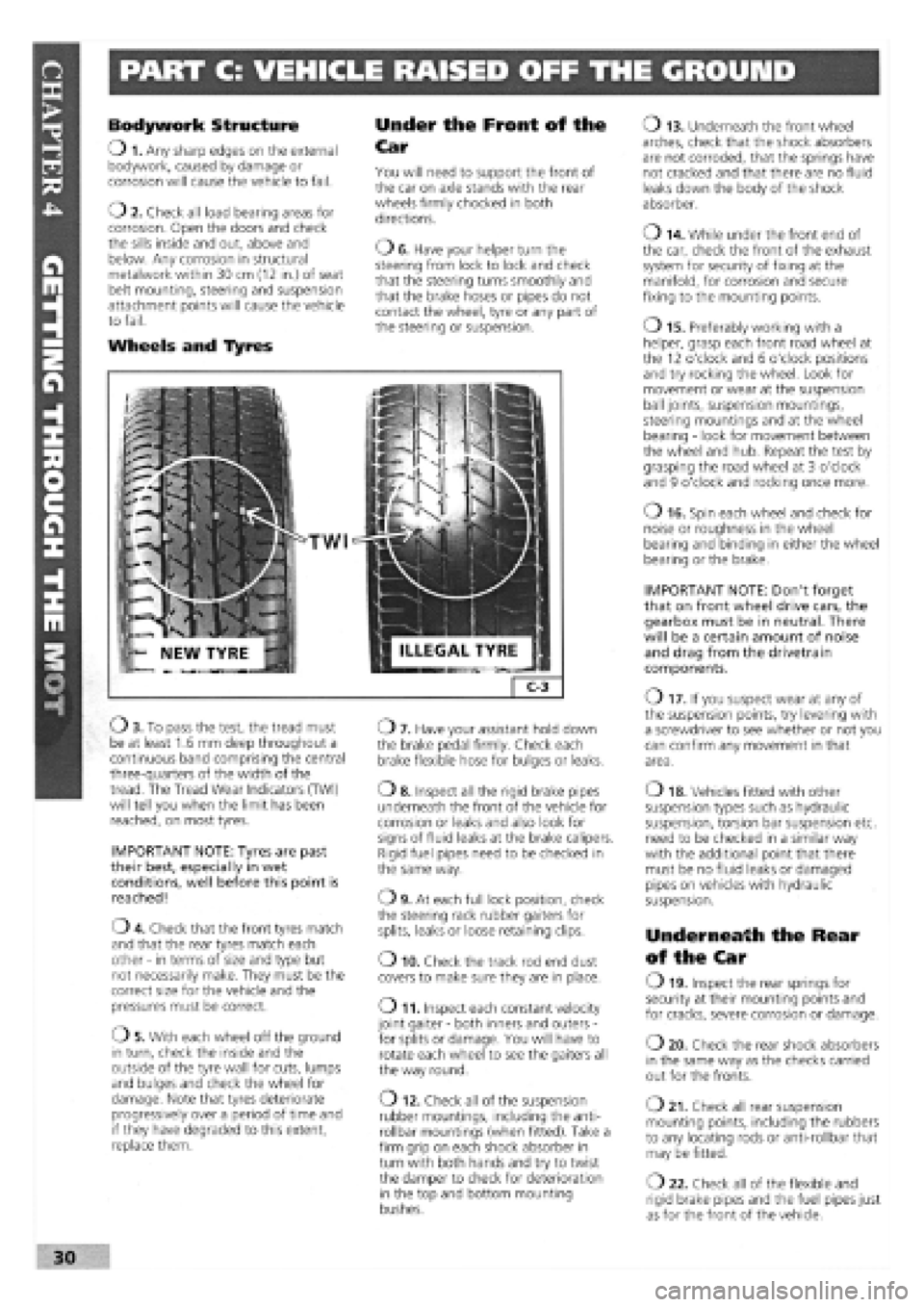
TWI
Ob . To pass the test, the tread must be at least 1.6 mm deep throughout a continuous band comprising the central three-quarters of the width of the tread. The Tread Wear Indicators (TWI) will tell you when the limit has been reached, on most tyres.
IMPORTANT NOTE: Tyres are past their best, especially in wet conditions, well before this point is reached!
04 . Check that the front tyres match and that the rear tyres match each other
-
in terms of size and type but not necessarily make. They must be the correct size for the vehicle and the pressures must be correct.
05 . With each wheel off the ground in turn, check the inside and the outside of the tyre wall for cuts, lumps and bulges and check the wheel for damage. Note that tyres deteriorate progressively over a period of time and if they have degraded to this extent, replace them.
07 . Have your assistant hold down the brake pedal firmly. Check each brake flexible hose for bulges or leaks.
o 8. Inspect all the rigid brake pipes underneath the front of the vehicle for corrosion or leaks and also look for signs of fluid leaks at the brake calipers. Rigid fuel pipes need to be checked in the same way.
09 . At each full lock position, check the steering rack rubber gaiters for splits, leaks or loose retaining clips.
o 10. Check the track rod end dust covers to make sure they are in place.
o 11. Inspect each constant velocity joint gaiter
-
both inners and outers
-
for splits or damage. You will have to rotate each wheel to see the gaiters all the way round.
O 12. Check all of the suspension rubber mountings, including the anti-rollbar mountings (when fitted). Take a firm grip on each shock absorber in turn with both hands and try to twist the damper to check for deterioration in the top and bottom mounting bushes.
o 13. Underneath the front wheel arches, check that the shock absorbers are not corroded, that the springs have not cracked and that there are no fluid leaks down the body of the shock absorber.
o 14. While under the front end of the car, check the front of the exhaust system for security of fixing at the manifold, for corrosion and secure fixing to the mounting points.
o 15. Preferably working with a helper, grasp each front road wheel at the 12 o'clock and 6 o'clock positions and try rocking the wheel. Look for movement or wear at the suspension ball joints, suspension mountings, steering mountings and at the wheel bearing
-
look for movement between the wheel and hub. Repeat the test by grasping the road wheel at 3 o'clock and 9 o'clock and rocking once more.
o 16. Spin each wheel and check for noise or roughness in the wheel bearing and binding in either the wheel bearing or the brake.
IMPORTANT NOTE: Don't forget that on front wheel drive cars, the gearbox must be in neutral. There will be a certain amount of noise and drag from the drivetrain components.
O 17. If you suspect wear at any of the suspension points, try levering with a screwdriver to see whether or not you can confirm any movement in that area.
o 18. Vehicles fitted with other suspension types such as hydraulic suspension, torsion bar suspension etc. need to be checked in a similar way with the additional point that there must be no fluid leaks or damaged pipes on vehicles with hydraulic suspension.
Underneath the Rear
of the Car
O 19. Inspect the rear springs for security at their mounting points and for cracks, severe corrosion or damage.
o 20. Check the rear shock absorbers in the same way as the checks carried out for the fronts.
o 21. Check all rear suspension mounting points, including the rubbers to any locating rods or anti-rollbar that may be fitted.
O 22. Check all of the flexible and rigid brake pipes and the fuel pipes just as for the front of the vehicle.
30
Page 30 of 171
PART G: BRAKING SYSTEM
Job 49. Check front brakes
Job 50. Check rear brakes
Job 51. Check/adjust handbrake
Job 52. Check brake pipes
Job 53. Change brake hydraulic fluid
SERVICE INTERVALS
C
C
C
C
E
Job 56. Check seat and seat belt mountings C
Job 57. Check headlight alignment C
Job 58. Check underbody C
Job 59. Check spare tyre B
Job 60. Change pollen filter C
Job 61. Replace airbag gas generator 10 years
PART I: ROAD TEST
PART H: BODYWORK & INTERIOR
Job 54. Lubricate hinges and locks
Job 55. Check windscreen
Job 62. Road test and specialist check. AFTER EVERY
SERVICE
ENGINE BAY LAYOUTS
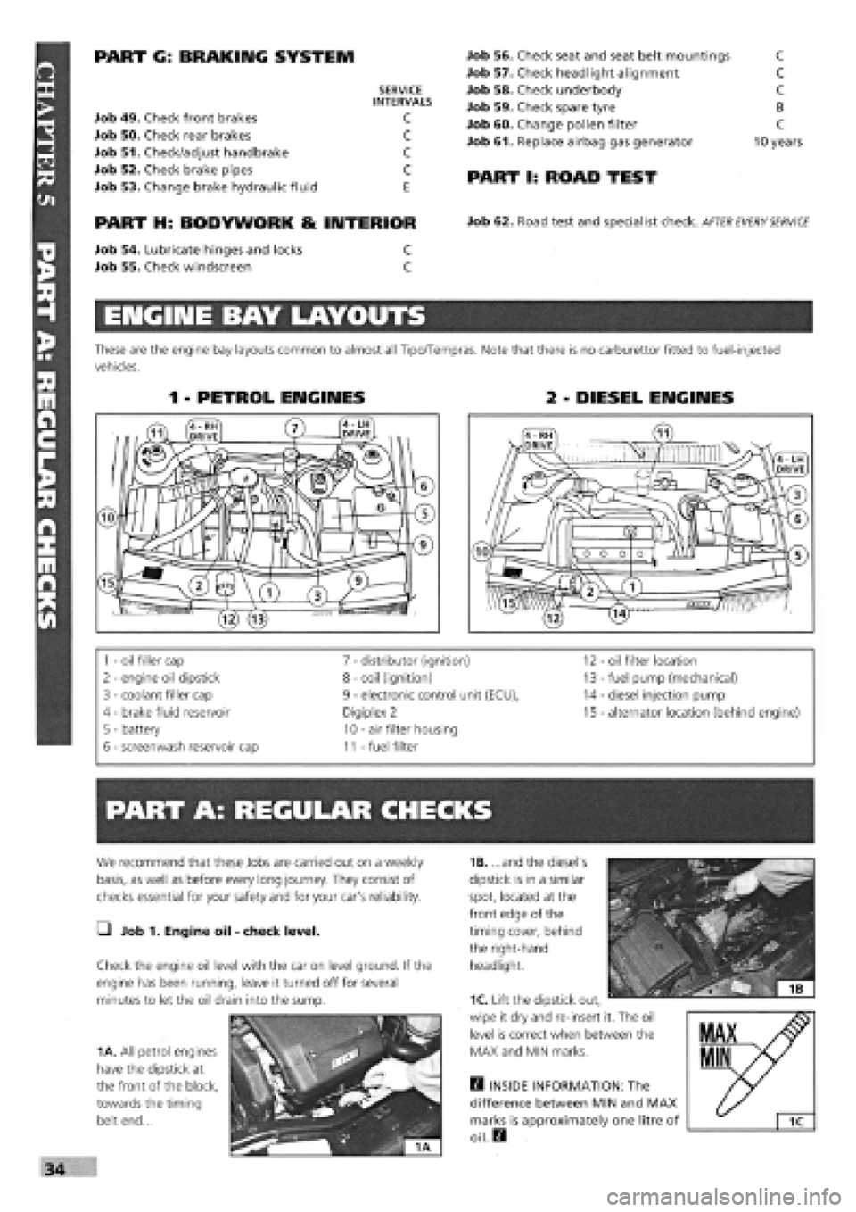
These are the engine bay layouts common to almost all Tipo/Tempras. Note that there is no carburettor fitted to fuel-injected
vehicles.
1 - PETROL ENGINES 2 - DIESEL ENGINES
1
-
oil filler cap 7
-
distributor (ignition) 12 - oil filter location
2
-
engine oil dipstick 8
-
coil (ignition) 13
-
fuel pump (mechanical)
3
-
coolant filler cap 9
-
electronic control unit (ECU), 14
-
diesel injection pump
4 - brake fluid reservoir Digiplex 2 15
-
alternator location (behind engine)
5 - battery 10
-
air filter housing
6
-
screenwash reservoir cap 11
-
fuel filter
PART A: REGULAR CHECKS
1B. ...and the diesel's
dipstick is in a similar
spot, located at the
front edge of the
timing cover, behind
the right-hand
headlight.
Q INSIDE INFORMATION: The
difference between MIN and MAX
marks is approximately one litre of
oil. Q
We recommend that these Jobs are carried out on a weekly
basis, as well as before every long journey. They consist of
checks essential for your safety and for your car's reliability.
• Job 1. Engine oil
-
check level.
Check the engine oil level with the car on level ground. If the
engine has been running, leave it turned off for several
minutes to let the oil drain into the sump.
1A. All petrol engines
have the dipstick at
the front of the block,
towards the timing
belt end...
1C. Lift the dipstick out,
wipe it dry and re-insert it. The oil
level is correct when between the
MAX and MIN marks.
Page 32 of 171
(ignition-ON) position and press down the button between the
two terminals on the reservoir cap
-
when fitted. The warning
light on the dash should light up. When no button is fitted,
unscrew and raise the cap (ignition key ON) to check the
warning light. Check the bulb, check the fuse, or have your
FIAT dealer repair the warning system, if faulty.
• Job 4. Battery
-
check electrolyte level.
FACT FILE: DISCONNECTING THE
BATTERY
• Many vehicles depend on a constant
power supply from the battery; with
these you find yourself in trouble if you
simply disconnect the battery. You
might find the car alarm goes off, or that the engine
management system forgets all it ever 'learned', making
the car feel odd to drive until it has re-programmed
itself. You might also find that the radio refuses to
operate until its correct security code is keyed into it.
• On cars with engine management systems and/or
coded radios, you must ensure the car has a constant
electrical supply, even with the battery removed. You
will need a separate 12 volt battery; put a self-tapping
screw into the positive lead near the battery terminal
before disconnecting it, and put a positive connection
to your other battery via this screw.
• Be EXTREMELY CAREFUL to wrap insulation tape
around the connection so that no short is caused. The
negative terminal on the other battery must be
connected to the car's bodywork.
SAFETY FIRST!
• The gas given off by a battery is highly explosive.
Never smoke, use a naked flame or allow a spark in
the battery compartment.
• Never disconnect the battery (it can cause sparking)
with the battery caps removed.
• All vehicle batteries contain sulphuric acid. If the
acid comes into contact with the skin or eyes, wash
immediately with copious amounts of cold water and
seek medjcal advice.
• Do not check the battery levels within half an hour
of the battery being charged with a separate battery
charger because the addition of fresh water could
cause electrolyte to flood out.
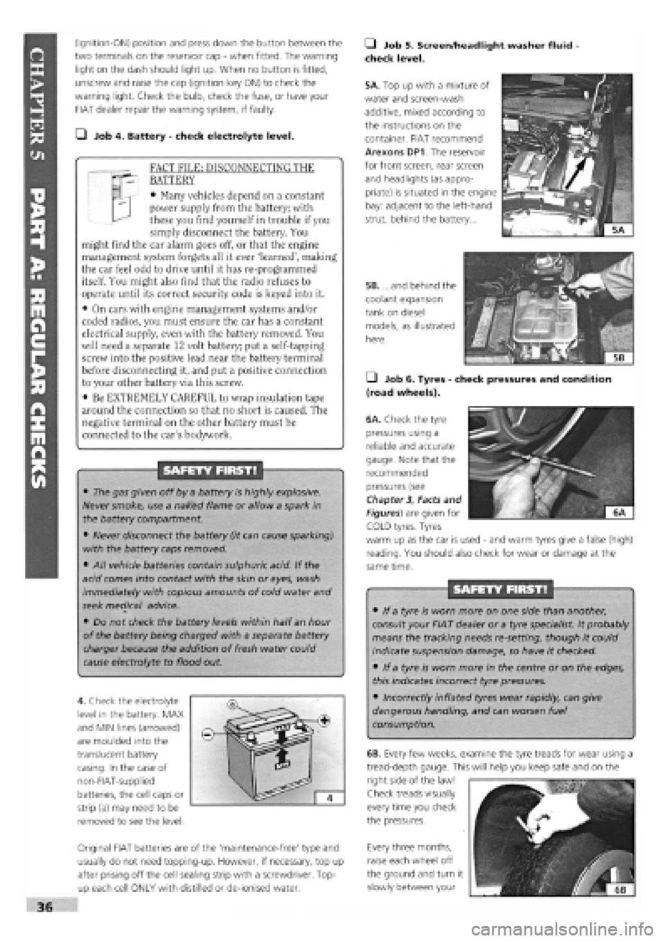
4. Check the electrolyte
level in the battery. MAX
and MIN lines (arrowed)
are moulded into the
translucent battery
casing. In the case of
non-FIAT-supplied
batteries, the cell caps or
strip (a) may need to be
removed to see the level.
Original FIAT batteries are of the 'maintenance-free' type and
usually do not need topping-up. However, if necessary, top up
after prising off the cell sealing strip with a screwdriver. Top-
up each cell ONLY with distilled or de-ionised water.
• Job 5. Screen/headlight washer fluid
check level.
5A. Top up with a mixture of
water and screen-wash
additive, mixed according to
the instructions on the
container. FIAT recommend
Arexons DP1. The reservoir
for front screen, rear screen
and headlights (as appro-
priate) is situated in the engine
bay: adjacent to the left-hand
strut, behind the battery...
5B. ...and behind the
coolant expansion
tank on diesel
models, as illustrated
here.
• Job 6. Tyres
-
check pressures and condition
(road wheels).
/
6A. Check the tyre
pressures using a
reliable and accurate
gauge. Note that the
recommended
pressures (see
Chapter
3,
Facts and
Figures) are given for ^^
iH^KKSEI ^ "'
COLD tyres. Tyres
warm up as the car is used
-
and warm tyres give a false (high)
reading. You should also check for wear or damage at the
same time.
SAFETY FIRST!
• If a tyre is worn more on one side than another,
consult your FIAT dealer or a tyre specialist. It probably
means the tracking needs re-setting, though it could
indicate suspension damage, so have it checked.
• If a tyre is worn more in the centre or on the edges,
this indicates incorrect tyre pressures.
• Incorrectly inflated tyres wear rapidly, can give
dangerous handling, and can worsen fuel
consumption.
Every three months,
raise each wheel off
the ground and turn it
slowly between your
36
6B. Every few weeks, examine the tyre treads for wear using a
tread-depth gauge. This will help you keep safe and on the
right side of the law!
Check treads visually
every time you check
the pressures.
Page 33 of 171
• Whenever a light fails to
work, check its fuse before
replacing the bulb.
• A blown bulb often causes a fuse to 'go' in
sympathy.
hands, looking and feeling for any bulges, tears or splits in the
tyre walls, especially the inner sidewalls. (See Job 59 for spare
tyre checks.)
H INSIDE INFORMATION: In time, rubber deteriorates,
increasing the risk of a blow-out. Keep your eye on the
sidewalls of older tyres. If you see any cracking, splits or
other damage scrap the tyre. If you're not sure, consult
your FIAT dealer or tyre specialist. Q
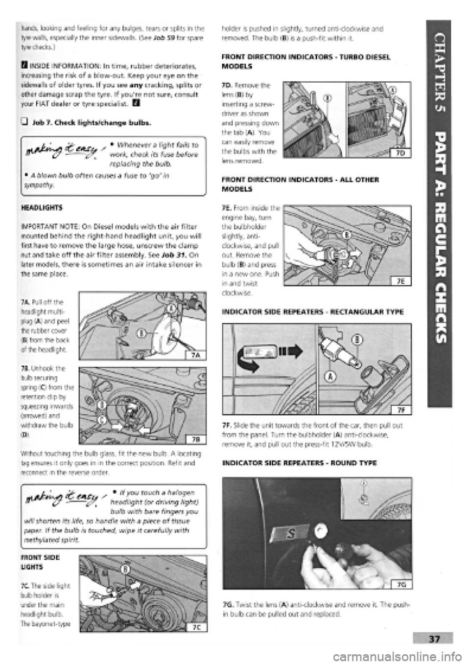
_) Job 7. Check lights/change bulbs.
7A. Pull off the
headlight multi-
plug (A) and peel
the rubber cover
(B) from the back
of the headlight.
7B. Unhook the
bulb securing
spring (C) from the
retention clip by
squeezing inwards
(arrowed) and
withdraw the bulb
(D).
Without touching the bulb glass, fit the new bulb. A locating
tag ensures it only goes in in the correct position. Refit and
reconnect in the reverse order.
HEADLIGHTS
IMPORTANT NOTE: On Diesel models with the air filter
mounted behind the right-hand headlight unit, you will
first have to remove the large hose, unscrew the clamp
nut and take off the air filter assembly. See Job 31. On
later models, there is sometimes an air intake silencer in
the same place.
7F. Slide the unit towards the front of the car, then pull out
from the panel. Turn the bulbholder (A) anti-clockwise,
remove it, and pull out the press-fit 12V/5W bulb.
INDICATOR SIDE REPEATERS
-
ROUND TYPE
holder is pushed in slightly, turned anti-clockwise and
removed. The bulb (B) is a push-fit within it.
FRONT DIRECTION INDICATORS
-
TURBO DIESEL
MODELS
7D. Remove the
lens (B) by
inserting a screw-
driver as shown
and pressing down
the tab (A). You
can easily remove
the bulbs with the
lens removed.
FRONT DIRECTION INDICATORS
-
ALL OTHER
MODELS
7E. From inside the
engine bay, turn
the bulbholder
slightly, anti-
clockwise, and pull
out. Remove the
bulb (B) and press
in a new one. Push
in and twist
clockwise.
INDICATOR SIDE REPEATERS
-
RECTANGULAR TYPE
CAS / * touc^ a halogen
• headlight (or driving light)
bulb with bare fingers you
will
shorten its life, so handle with a piece of
tissue
paper. If the bulb is touched, wipe it carefully with
methylated spirit.
FRONT SIDE
LIGHTS
7C.
The side light
bulb holder is
under the main
headlight bulb.
The bayonet-type
7G. Twist the lens (A) anti-clockwise and remove it. The push-
in bulb can be pulled out and replaced.
Page 39 of 171
—I Job 13. Check cooling system.
SAFETY FIRST!
• The coolant level should be checked
-
and the
cooling system worked on, ONLY WHEN THE
COOLANT IS COLD. If you remove the pressure cap or
bleed screws when the engine is hot, scalding coolant
will spurt out.
• Keep anti-freeze away from children. If it is acciden-
tally swallowed or contacts skin or eyes, rinse
immediately with plenty of water and seek immediate
medical help.
Examine the cooling system hoses, looking for signs of
splitting, chafing and perishing. Squeeze the top and bottom
radiator hoses. Any hard, brittle areas or crackling sounds tell
you that the hoses are decomposing from the inside
-
replace-
ments needed!
SAFETY FIRST!
If
a
clearance is outside the tolerances shown in Chapter 3,
Facts
and Figures, the relevant shim will have to be changed.
New
shims
are available from your FIAT dealer. This work is
fully described in Chapter
6,
Repairs and Replacements.
10E. You must
always use a new
gasket, especially in
view of the oil level
mentioned earlier.
Clean the housing
and
cover faces and
use
the gasket dry.
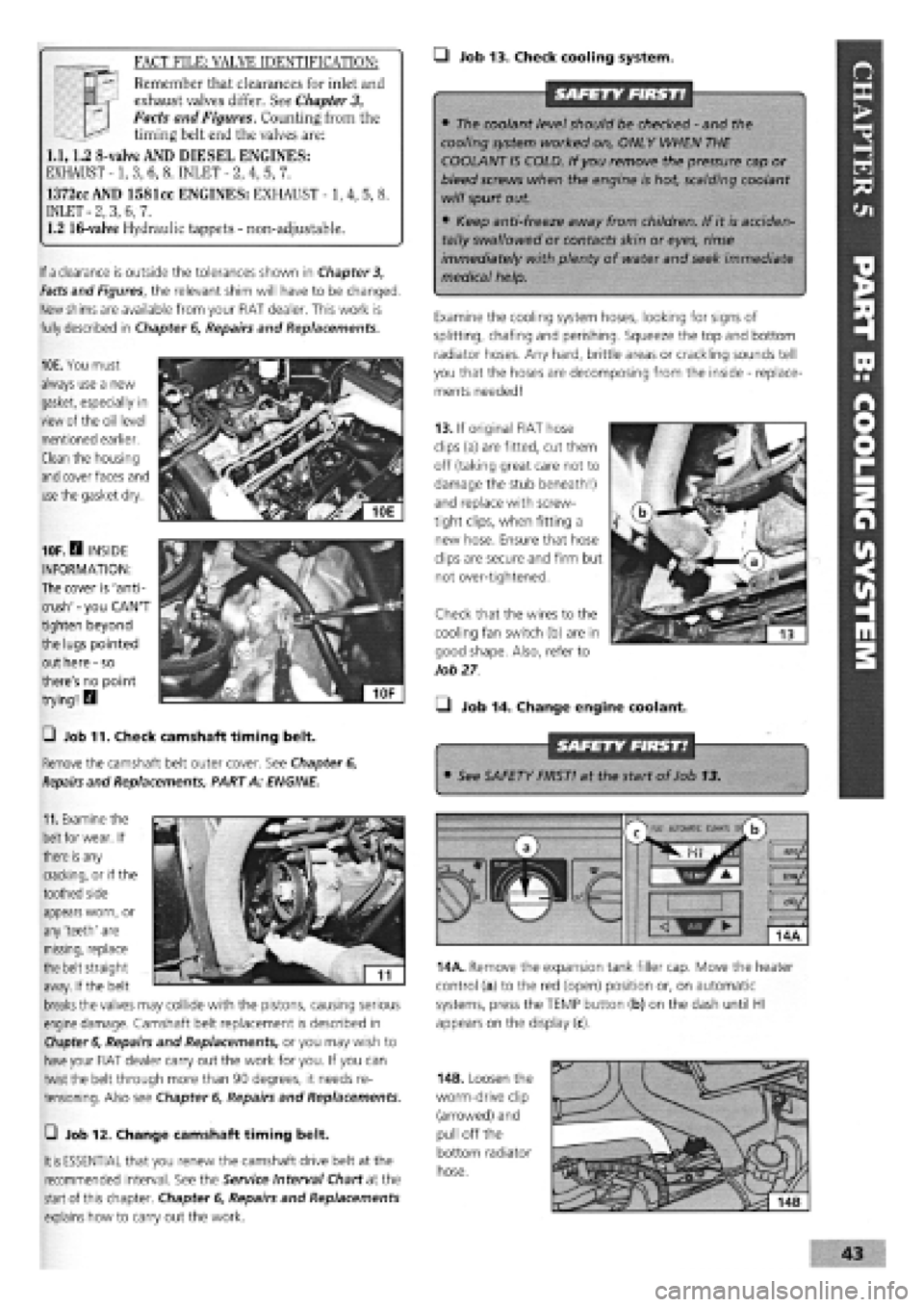
11.
Examine the
belt
for wear. If
there
is
any
cracking, or if the
toothed side
10F.H INSIDE
INFORMATION:
The cover is 'anti-
crush'
-
you CAN'T
tighten beyond
the lugs pointed
out here
-
so
there's no point
trying! H
0 Job 11. Check camshaft timing belt.
Remove the camshaft belt outer cover. See Chapter 6,
Repairs
and Replacements, PART A: ENGINE.
FACT FILE: VALVE IDENTIFICATION:
T
—
Remember that clearances for inlet and
3™ exhaust valves differ. See
Chapter
3,
Facts and Figures. Counting from the
—^ timing belt end the valves are:
1.1,1.2 8-valve AND DIESEL ENGINES:
EXHAUST -1, 3, 6, 8. INLET
-
2, 4, 5, 7.
1372cc AND 1581cc ENGINES: EXHAUST -1, 4, 5, 8.
INLET
-
2, 3, 6, 7.
1.2 16-valve Hydraulic tappets
-
non-adjustable.
13. If original FIAT hose
clips (a) are fitted, cut them
off (taking great care not to
damage the stub beneath!)
and replace with screw-
tight clips, when fitting a
new hose. Ensure that hose
clips are secure and firm but
not over-tightened.
Check that the wires to the
cooling fan switch (b) are in
good shape. Also, refer to
Job
27
• Job 14. Change engine coolant.
• See SAFETY FIRST! at the start of Job 13.
appears worn, or
any 'teeth' are
missing, replace
the belt straight
away. If the belt
breaks
the valves may collide with the pistons, causing serious
engine damage. Camshaft belt replacement is described in
Chapter 6,
Repairs and Replacements, or you may wish to
have
your FIAT dealer carry out the work for you. If you can
twist the belt through more than 90 degrees, it needs re-
tensioning. Also see Chapter
6,
Repairs and Replacements.
m
AUtOKAlIC CtMAU s/
b
14A. Remove the expansion tank filler cap. Move the heater
control (a) to the red (open) position or, on automatic
systems, press the TEMP button (b) on the dash until HI
appears on the display (c).
—i Job 12. Change camshaft timing belt.
It is
ESSENTIAL that you renew the camshaft drive belt at the
recommended interval. See the Service Interval Chart at the
start
of this chapter. Chapter
6,
Repairs and Replacements
explains how to carry out the work.
14B. Loosen the
worm-drive clip
(arrowed) and
pull off the
bottom radiator
hose.