change wheel FIAT TEMPRA 1988 Service And Repair Manual
[x] Cancel search | Manufacturer: FIAT, Model Year: 1988, Model line: TEMPRA, Model: FIAT TEMPRA 1988Pages: 171, PDF Size: 18.05 MB
Page 3 of 171
Mains Electricity
Avoid the use of mains electricity when working on the vehicle,
whenever possible. Use rechargeable tools and a DC inspection
lamp, powered from a remote 12V battery
-
both are much
safer. However, if you do use mains-powered equipment,
ensure that the appliance is wired correctly to its plug, that
where necessary it is properly earthed (grounded), and that the
fuse is of the correct rating for the appliance. Do not use any
mains powered equipment in damp conditions or in the vicinity
of fuel, fuel vapour or the vehicle battery.
Always use an RCD (Residual Current Device) circuit breaker
with mains electricity. Then, if there is a short, the RCD circuit
breaker minimises the risk of electrocution by instantly cutting
the power supply.
Ignition System
Never work on the ignition system with the ignition switched
on, or with the engine being turned over on the starter, or
running and you are recommended never to do so.
Touching certain parts of the ignition system, such as the HT
leads, distributor cap, ignition coil etc., can result in a severe
electric shock or physical injury as a hand is pulled sharply away.
Voltages produced by electronic ignition systems are much
higher than those produced by conventional systems and could
prove fatal, particularly to people with cardiac pacemaker
implants. Consult your handbook or main dealer if in any
doubt.
Cooling Fan
On many vehicles, the electric cooling fan can switch itself on
even with the ignition turned off. This is especially likely after
driving the car and parking it before turning off, after which
heat rises to the top of the engine and turns the fan on,
suddenly and without warning. If you intend working in the
engine bay, it's best to do so when the engine is cold, to
disconnect the battery, or keep away from the fan, if neither of
these are possible.
Battery
Never cause a spark, smoke, or allow a naked light near the
vehicle's battery, even in a well ventilated area. Highly explosive
hydrogen gas is given off as part of the charging process.
Battery terminals on the car should be shielded, since a spark
can be caused by any metal object which touches the battery's
terminals or connecting straps.
IMPORTANT NOTE: Before disconnecting the battery earth
(ground) terminal read the relevant FACT FILE in Chapter 5
regarding saving computer and radio settings.)
When using a battery charger, switch off the power supply
before the battery charger leads are connected or disconnected.
If the battery is not of the 'sealed-for-life' type, loosen the filler
plugs or remove the cover before charging. For best results the
battery should be given a low rate trickle charge overnight. Do
not charge at an excessive rate or the battery may burst.
Always wear gloves and goggles when carrying or when
topping up the battery. Acid electrolyte is extremely corrosive
and must not be allowed to contact the eyes, skin or clothes.
Brakes and Asbestos
Obviously, a car's brakes are among its most important safety
related items. ONLY work on your vehicle's braking system if
you are trained and competent to do so. If you have not been
trained in this work, but wish to carry out the jobs described in
this book, we strongly recommend that you have a garage or
qualified mechanic check your work before using the car.
Whenever you work on the braking system components, or
remove front or rear brake pads or shoes: i) wear an efficient
particle mask; ii) wipe off all brake dust from the brakes after
spraying on a proprietary brand of brake cleaner (never blow
dust off with compressed air); iii) dispose of brake dust and
discarded shoes or pads in a sealed plastic bag; iv) wash your
hands thoroughly after you have finished working on the
brakes and certainly before you eat or smoke; v) replace shoes
and pads only with asbestos-free shoes or pads. Note that
asbestos brake dust can cause cancer if inhaled; vi) always
replace brake pads and/or shoes in complete 'axle' sets of four
-
never replace the pads/shoes on one wheel only.
Brake Fluid
Brake fluid absorbs moisture rapidly from the air and can
become dangerous resulting in brake failure. You should
change the fluid in accordance with your vehicle manufacturer's
recommendations or as advised in this book. Never store (or
use) an opened container of brake fluid. Dispose of the
remainder at your Local Authority Waste Disposal Site, in the
designated disposal unit, not with general waste or with waste
oil.
Engine Oils
Always wear disposable plastic or rubber gloves when draining
the oil from your engine, i) Note that the drain plug and the oil
are often hotter than you expect. Wear gloves if the plug is too
hot to touch and keep your hand to one side so that you are
not scalded by the spurt of oil as the plug comes away; ii) There
are very real health hazards associated with used engine oil. In
the words of one manufacturer's handbook "Prolonged and
repeated contact may cause serious skin disorders, including
dermatitis and cancer." Use a barrier cream on your hands and
try not to get oil on them. Always wear gloves and wash your
hands with hand cleaner soon after carrying out the work. Keep
oil out of the reach of children; iii) NEVER, EVER dispose of old
engine oil into the ground or down a drain. In the UK, and in
most EC countries, every local authority must provide a safe
means of oil disposal. In the UK, try your local Environmental
Health Department for advice on waste disposal facilities.
Plastic Materials
Many of the materials used (polymers, resins, adhesives and
materials acting as catalysts and accelerators) contain dangers in
the form of poisonous fumes, skin irritants, and the risk of fire
Page 6 of 171
• Repeat this operation three more times until the
complete code number has been entered, if the code
has been entered in correctly LED B will start flashing.
• Release button A (see illustration
1B).
Red LED B
flashes for 8 seconds indicating the new remote unit's
code has been stored.
IMPORTANT NOTE: If the LED does not illuminate
when remote unit button (illustration 1B, button
O is pressed, change the remote unit's battery.
• Insert the emergency key A into the emergency switch
slot in the glove compartment turn the key to the left to
switch the alarm off (see inset).
• Turn the key back towards its original position to
switch the alarm system back on.
IMPORTANT NOTE: As the alarm system absorbs
energy, if you are not planning on using the car
for a long period of time, turn the alarm exclusion
key to the off position, so as not to run the vehicle
battery down.
• 2. IGNITION SWITCH AND
STEERING COLUMN LOCK
IGNITION SWITCH
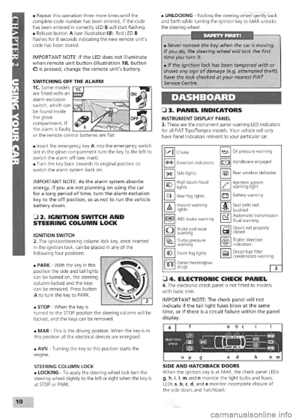
2. The ignition/steering column lock key, once inserted
in the ignition lock, can be placed in any of the
following four positions:
• PARK
-
With the key in this
position the side and tail lights
can be turned on, the steering
column locked and the keys
can be removed. Press button
A to turn the key to PARK.
• STOP
-
When the key is
turned to the STOP position the steering column will be
locked, and the keys can be removed.
• MAR
-
This is the driving position. When the key is in
this position all the electrical devices are energised.
• AW
-
Turning the key to this position starts the
engine.
STEERING COLUMN LOCK
• LOCKING
-
To apply the steering wheel lock turn the
steering wheel slightly to the left or right when the key is
at STOP or PARK.
• UNLOCKING
-
Rocking the steering wheel gently back
and forth while turning the ignition key to MAR unlocks
the steering wheel.
• 3. PANEL INDICATORS
INSTRUMENT DISPLAY PANEL
3. These are the instrument panel warning LED indicators
for all FIAT Tipo/Tempra models. Your vehicle will only
have Panel Indicators relevant to your particular car.
• 4. ELECTRONIC CHECK PANEL
4. The electronic check panel is not fitted to models
with basic trim.
IMPORTANT NOTE: The check panel will not
indicate if the tail light fuses blow at the same
time, or if there is a circuit failure within the panel
display.
SIDE AND HATCHBACK DOORS
When the ignition key is at MAR, the check panel LEDs
g, h, i, I, m and n monitor the light bulbs and fuses.
LEDs a, b, c, d, and e monitor incomplete closure of
the side doors and hatchback.
• Never remove the key when the car is moving.
If you do, the steering wheel will lock the first
time you turn it.
• If the ignition lock has been tampered with or
shows any sign of damage (e.g. attempted theft),
have the lock checked at your nearest FIAT
Service Centre.
M Choke Oil pressure warning
Direction indicators (®) Handbrake engaged
-X: Side lights m Rear window defroster
10 High beam head
lights '•y Injection system warning light
<1* Rear fog lights • Battery warning
A Hazard warning lights A Seat belts not
buckled
m ABS brake warning a Automatic transmission fluid warning
o Brake pad wear warning a Doors not properly closed
Turbo pressure warning Trailer direction indicators
10 Front fog lights a Diesel fuel filter condenstate warning
•515" Diesel heater/glow •515" plugs 3
SWITCHING OFF THE ALARM
1C. Some models
are fitted with an
alarm exclusion
switch, which can
be found inside
the glove
compartment. If
the alarm is faulty
or the remote control batteries are flat:
Page 27 of 171
O 23. Have your assistant press down firmly on the brake pedal while you check the rear brake flexible hoses for bulges, splits or other deterioration.
o 24. Check the fuel tank for leaks or corrosion. Remember also to check the fuel filler cap
-
a correctly sealing filler cap is a part of the MoT test.
O 25. Examine the handbrake mechanism. Frayed or broken cables or worn mounting points, either to the bodywork or in the linkage will all be failure points.
o 26. Check each of the rear wheel
bearings as for the fronts.
o 27. Spin each rear wheel and check that neither the wheel bearings nor the brakes are binding. Pull on and let off the handbrake and check once again to make sure that the handbrake mechanism is releasing.
SAFETY FIRST!
• Only run the car out of doors.
• Beware of burning yourself on a hot exhaust system.
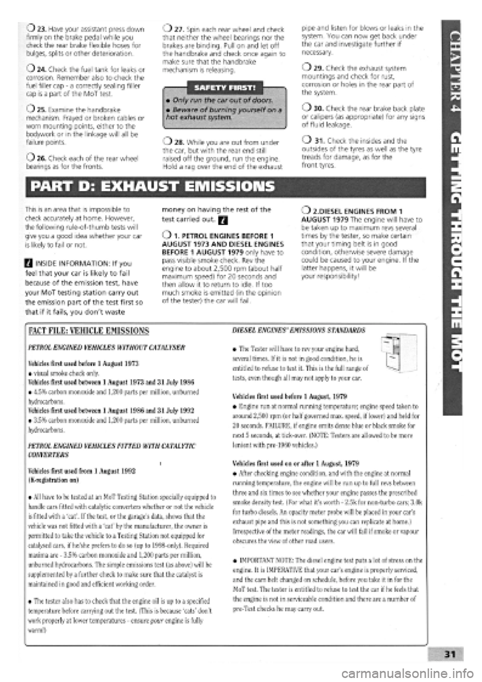
o 28. While you are out from under the car, but with the rear end still raised off the ground, run the engine. Hold a rag over the end of the exhaust
pipe and listen for blows or leaks in the system. You can now get back under the car and investigate further if necessary.
o 29. Check the exhaust system mountings and check for rust, corrosion or holes in the rear part of the system.
o 30. Check the rear brake back plate or calipers (as appropriate) for any signs of fluid leakage.
o 31. Check the insides and the outsides of the tyres as well as the tyre treads for damage, as for the front tyres.
PART D: EXHAUST EMISSIONS
This is an area that is impossible to
check accurately at home. However,
the following rule-of-thumb tests will
give you a good idea whether your car
is likely to fail or not.
H INSIDE INFORMATION: If you
feel that your car is likely to fail
because of the emission test, have
your MoT testing station carry out
the emission part of the test first so
that if it fails, you don't waste
money on having the rest of the
test carried out. Q
O 1. PETROL ENGINES BEFORE 1 AUGUST 1973 AND DIESEL ENGINES BEFORE 1 AUGUST 1979 only have to pass visible smoke check. Rev the engine to about 2,500 rpm (about half maximum speed) for 20 seconds and then allow it to return to idle. If too much smoke is emitted (in the opinion of the tester) the car will fail.
O 2.DIESEL ENGINES FROM 1 AUGUST 1979 The engine will have to be taken up to maximum revs several times by the tester, so make certain that your timing belt is in good condition, otherwise severe damage could be caused to your engine. If the latter happens, it will be your responsibility!
FACT FILE: VEHICLE EMISSIONS
PETROL
ENGINED VEHICLES WITHOUT
CATALYSER
Vehicles first used before 1 August 1973
• visual smoke check only.
Vehicles first used between 1 August 1973 and 31 July 1986
• 4.5% carbon monoxide and 1,200 parts per million, unburned
hydrocarbons.
Vehicles first used between 1 August 1986 and 31 July 1992
• 3.5% carbon monoxide and 1,200 parts per million, unburned
hydrocarbons.
PETROL ENGINED VEHICLES FITTED WITH
CATALYTIC
CONVERTERS
i
Vehicles first used from 1 August 1992
(K-registration on)
• All have to be tested at an MoT Testing Station specially equipped to
handle cars fitted with catalytic converters whether or not the vehicle
is fitted with a 'cat'. If
the
test, or the garage's data, shows that the
vehicle was not fitted with a 'cat' by the manufacturer, the owner is
permitted to take the vehicle to
a
Testing Station not equipped for
catalysed cars, if he/she prefers to do so (up to 1998-only). Required
maxima are
-
3.5% carbon monoxide and 1,200 parts per million,
unburned hydrocarbons. The simple emissions test (as above) will be
supplemented by a further check to make sure that the catalyst is
maintained in
good
and efficient working order.
• The tester also has to check that the engine oil is up to a specified
temperature before carrying out the test. (This is because 'cats' don't
work properly at lower temperatures
-
ensure your engine is fully
warm!)
DIESEL ENGINES'EMISSIONS
STANDARDS
• The Tester will have to rev your engine hard,
several times. If it is not in good condition, he is
entitled to refuse to test it. This is the full range of
tests, even though all may not apply to your car.
Vehicles first used before 1 August, 1979
• Engine run at normal running temperature; engine speed taken to
around 2,500 rpm (or half
governed
max. speed, if lower) and held for
20 seconds. FAILURE, if engine emits dense blue or black smoke for
next 5 seconds, at tick-over. (NOTE: Testers are allowed to be more
lenient with pre-1960 vehicles.)
Vehicles first used on or after 1 August, 1979
• After checking engine condition, and with the engine at normal
running temperature, the engine will be run up to full revs between
three and six times to see whether your engine passes the prescribed
smoke density test. (For what it's worth
-
2.5k for non-turbo cars; 3.0k
for turbo diesels. An opacity meter probe will be placed in your car's
exhaust pipe and this is not something you can replicate at home.)
Irrespective of the meter readings, the car will fail if
smoke
or vapour
obscures the view of other road users.
• IMPORTANT NOTE: The diesel engine test puts a lot of stress on the
engine. It is IMPERATIVE that your car's engine is properly serviced,
and the cam belt changed on schedule, before you take it in for the
MoT test. The tester is entitled to refuse to test the car if
he
feels that
the engine is not in serviceable condition and there are a number of
pre-Test checks he may carry out.
Page 29 of 171
Thanks
are due to the excellent, knowledgeable and helpful staff at FIAT main dealers, Ryauto of Amblecote, in the West
Midlands for supplying vehicles and for their assistance with this chapter. In particular, thanks are due to the efficient Maurice
Hough, Service Manager, the experienced Foreman, Tony Morris, and young demon mechanic, Matthew Worsfold.
Some of the suggested inspection/replacement intervals may not correspond to those shown in the original handbook. The suggested
schedule, based on FIAT'S recommendations, takes into account the age of the vehicle and the annual MoT test in the UK.
In practice, because of the split between (mainly) 12 month/9,000 mile and 18 month/13,500 mile intervals, you will need to
service your Tipo or Tempra at most, if not every, 6 month interval.
IMPORTANT NOTE: Each service should be carried out at EITHER the recommended mileage OR the recommended time
interval, whichever comes first.
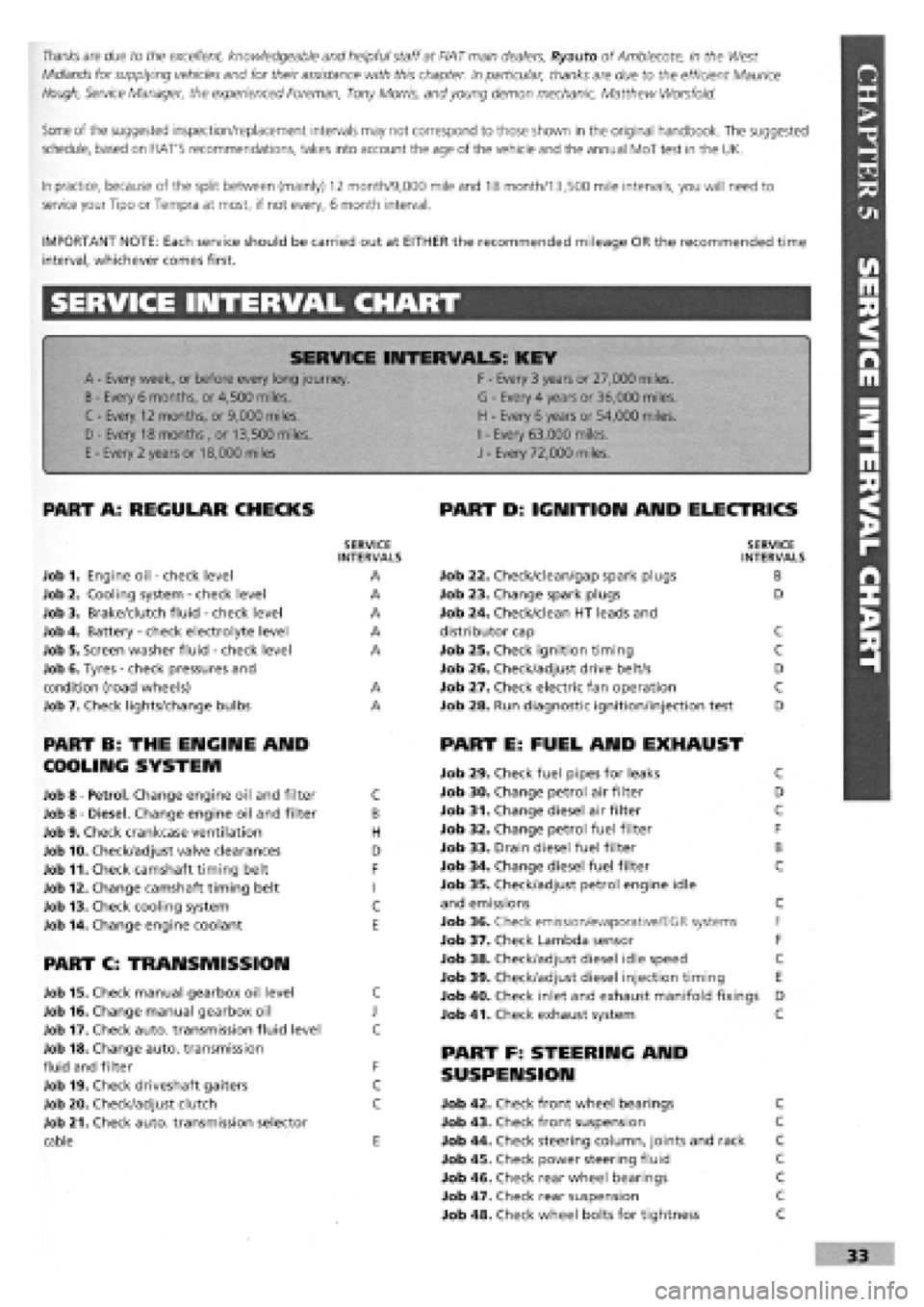
SERVICE INTERVAL CHART
SERVICE INTERVALS: KEY
A
-
Every week, or before every long journey. F
-
Every 3 years or 27,000 miles.
B
-
Every 6 months, or 4,500 miles. G
-
Every 4 years or 36,000 miles.
C - Every 12 months, or 9,000 miles. H
-
Every 6 years or 54,000 miles.
I
-
Every 63,000 miles. D - Every 18 months , or 13,500 miles.
H
-
Every 6 years or 54,000 miles.
I
-
Every 63,000 miles.
E
-
Every 2 years or 18,000 miles J
-
Every 72,000 miles.
PART A: REGULAR CHECKS
SERVICE INTERVALS
Job 1. Engine oil
-
check level A
Job 2. Cooling system
-
check level A
Job 3. Brake/clutch fluid
-
check level A
Job 4. Battery
-
check electrolyte level A
Job 5. Screen washer fluid
-
check level A
Job 6. Tyres
-
check pressures and
condition (road wheels) A
Job 7. Check lights/change bulbs A
PART B: THE ENGINE AND
COOLING SYSTEM
Job 8
-
Petrol. Change engine oil and filter C
Job 8
-
Diesel. Change engine oil and filter B
Job 9. Check crankcase ventilation H
Job 10. Check/adjust valve clearances D
Job 11. Check camshaft timing belt F
Job 12. Change camshaft timing belt I
Job 13. Check cooling system C
Job 14. Change engine coolant E
PART C: TRANSMISSION
Job 15. Check manual gearbox oil level C
Job 16. Change manual gearbox oil J
Job 17. Check auto, transmission fluid level C
Job 18. Change auto, transmission
fluid and filter F
Job 19. Check driveshaft gaiters C
Job 20. Check/adjust clutch C
Job 21. Check auto, transmission selector
cable E
PART D: IGNITION AND ELECTRICS
SERVICE INTERVALS
Job 22. Check/clean/gap spark plugs B
Job 23. Change spark plugs D
Job 24. Check/clean HT leads and
distributor cap C
Job 25. Check ignition timing C
Job 26. Check/adjust drive belt/s D
Job 27. Check electric fan operation C
Job 28. Run diagnostic ignition/injection test D
PART E: FUEL AND EXHAUST
Job 29. Check fuel pipes for leaks C
Job 30. Change petrol air filter D
Job 31. Change diesel air filter C
Job 32. Change petrol fuel filter F
Job 33. Drain diesel fuel filter B
Job 34. Change diesel fuel filter C
Job 35. Check/adjust petrol engine idle
and emissions C
Job 36. Check emission/evaporative/EGR systems F
Job 37. Check Lambda sensor F
Job 38. Check/adjust diesel idle speed C
Job 39. Check/adjust diesel injection timing E
Job 40. Check inlet and exhaust manifold fixings D
Job 41. Check exhaust system C
PART F: STEERING AND
SUSPENSION
Job 42. Check front wheel bearings C
Job 43. Check front suspension C
Job 44. Check steering column, joints and rack C
Job 45. Check power steering fluid C
Job 46. Check rear wheel bearings C
Job 47. Check rear suspension C
Job 48. Check wheel bolts for tightness C
Page 37 of 171
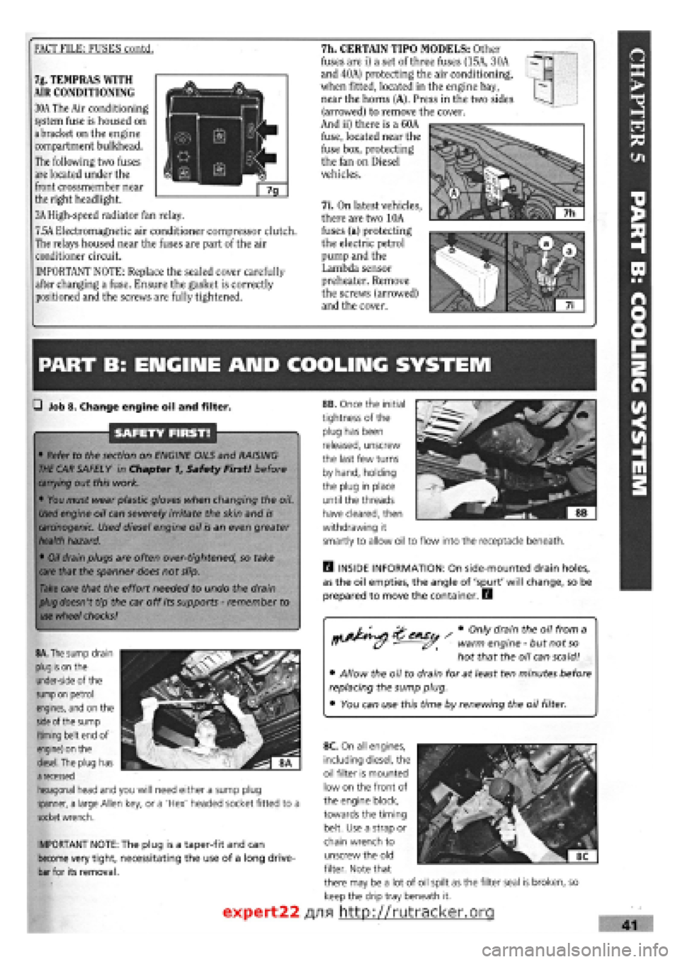
FACT FILE: FUSES contd. 7h. CERTAIN TIPO MODELS: Other
fuses are i) a set of three fuses (15A, 30A
and 40A) protecting the air conditioning,
when fitted, located in the engine bay,
near the horns (A). Press in the two sides
(arrowed) to remove the cover.
And ii) there is a 60A
fuse, located near the
fuse box, protecting
the fan on Diesel
vehicles.
7i. On latest vehicles,
there are two 10A
fuses (a) protecting
the electric petrol
pump and the
Lambda sensor
preheater. Remove
the screws (arrowed)
and the cover.
7g. TEMPRAS WITH
AIR CONDITIONING
30A The Air conditioning
system fuse is housed on
a bracket on the engine
compartment bulkhead.
The following two fuses
are located under the
front crossmember near
the right headlight.
3A High-speed radiator fan relay.
7.5A Electromagnetic air conditioner compressor clutch.
The relays housed near the fuses are part of the air
conditioner circuit.
IMPORTANT NOTE: Replace the sealed cover carefully
after changing a fuse. Ensure the gasket is correctly
positioned and the screws are fully tightened.
PART B: ENGIIME AND COOLING SYSTEM
Q Job 8. Change engine oil and filter.
SAFETY FIRST!
• Refer to the section on ENGINE OILS and RAISING
THE
CAR SAFELY in Chapter f, Safety First! before
carrying
out this work.
• You must wear plastic gloves when changing the oil.
Used
engine oil can severely irritate the skin and
is
carcinogenic.
Used diesel engine oil is an even greater
health
hazard.
•
Oil
drain plugs are often over-tightened, so take
care
that the spanner does not slip.
Take
care that the effort needed to undo the drain
plug
doesn't tip the car off its supports
-
remember to
use
wheel
chocks!
rtj&^si ' # °nly dram theu 0,7 fr°m a ff (y warm engine
-
but not
so
hot that the oil can scald!
• Allow the oil to drain for at least ten minutes before
replacing the sump plug.
• You can use this time by renewing the oil filter.
IMPORTANT NOTE: The plug is a taper-fit and can
become very tight, necessitating the use of a long drive-
bar for its removal.
H INSIDE INFORMATION: On side-mounted drain holes,
as the oil empties, the angle of 'spurt' will change, so be
prepared to move the container. E3
8A. The
sump drain
plug is on
the
under-side of the
sump on
petrol
engines, and on the
side
of the sump
(timing belt end of
engine) on the
diesel.
The plug has
a
recessed
hexagonal head and you will need either a sump plug
spanner, a large Allen key, or a 'Hex' headed socket fitted to a
socket
wrench.
8B. Once the initial
tightness of the
plug has been
released, unscrew
the last few turns
by hand, holding
the plug in place
until the threads
have cleared, then
withdrawing it
smartly to allow oil to flow into the receptacle beneath.
expert22
8C. On all engines,
including diesel, the
oil filter is mounted
low on the front of
the engine block,
towards the timing
belt. Use a strap or
chain wrench to
unscrew the old
filter. Note that
there may be a lot of oil spilt as the filter seal is broken, so
keep the drip tray beneath it.
/yifl http://rutracker.org
Page 56 of 171
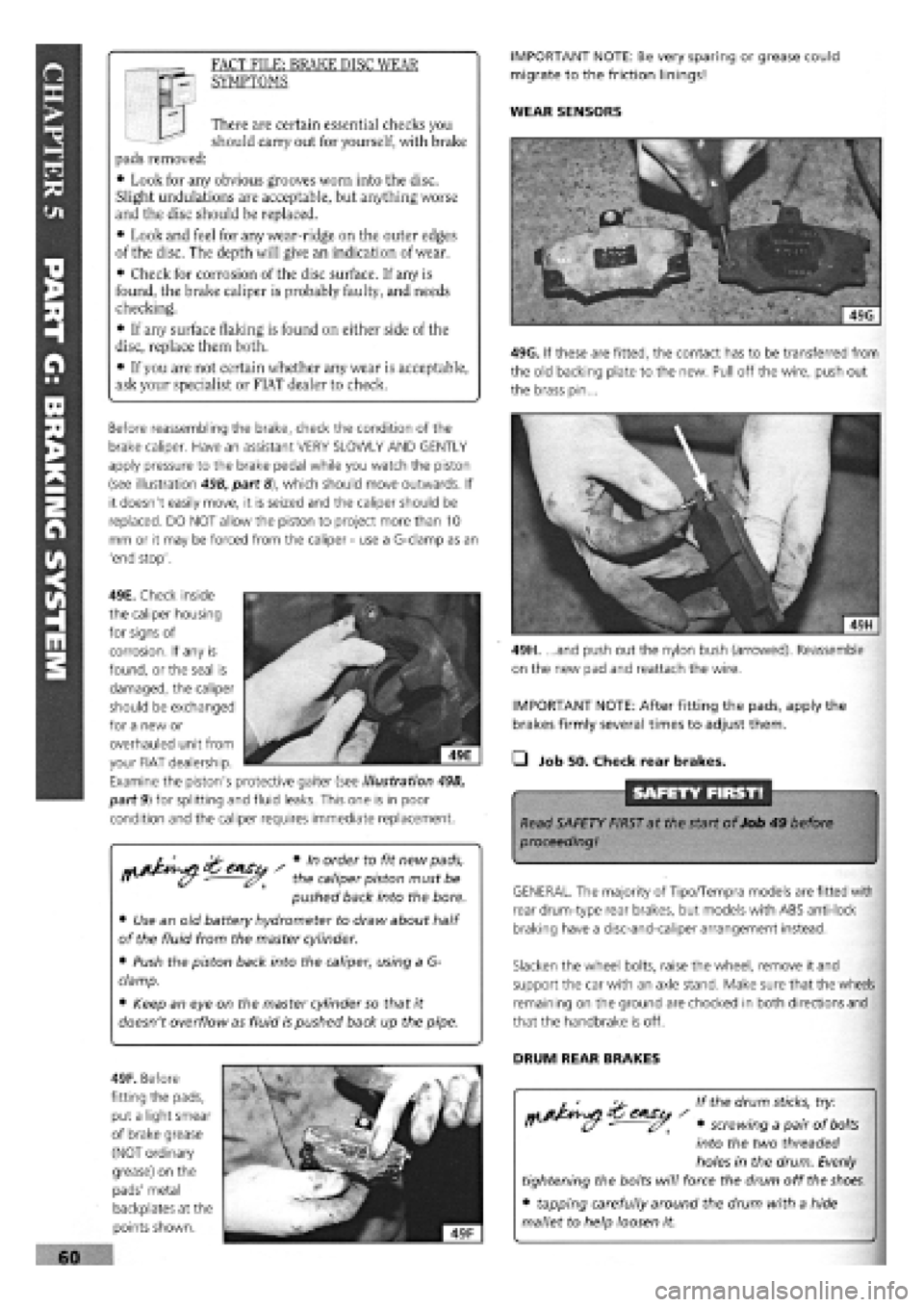
49H. ...and push out the nylon bush (arrowed). Reassemble
on the new pad and reattach the wire.
IMPORTANT NOTE: After fitting the pads, apply the
brakes firmly several times to adjust them.
• Job 50. Check rear brakes.
SAFETY FIRST!
Read SAFETY FIRST at the start of Job 49 before
proceeding!
GENERAL. The majority of Tipo/Tempra models are fitted with
rear drum-type rear brakes, but models with ABS anti-lock
braking have a disc-and-caliper arrangement instead.
Slacken the wheel bolts, raise the wheel, remove it and
support the car with an axle stand. Make sure that the wheels
remaining on the ground are chocked in both directions and
that the handbrake is off.
DRUM REAR BRAKES
If the drum
sticks,
try:
• screwing a pair of
bolts
into the two threaded
holes in the drum. Evenly
tightening the bolts will force the drum off the
shoes.
• tapping carefully around the drum with a hide
mallet to help loosen it.
s Vn order to fit new pads,
r> - the caliper piston must be
pushed back into the bore.
• Use an old battery hydrometer to draw about half
of the fluid from the master cylinder.
• Push the piston back into the caliper, using a G-
clamp.
• Keep an eye on the master cylinder so that it
doesn't overflow as fluid is pushed back up the pipe.
IMPORTANT NOTE: Be very sparing or grease could
migrate to the friction linings!
WEAR SENSORS I I There are certain essential checks you
should carry out for yourself, with brake
pads removed:
• Look for any obvious grooves worn into the disc.
Slight undulations are acceptable, but anything worse
and the disc should be replaced.
• Look and feel for any wear-ridge on the outer edges
of the disc. The depth will give an indication of wear.
• Check for corrosion of the disc surface. If any is
found, the brake caliper is probably faulty, and needs
checking.
• If any surface flaking is found on either side of the
disc, replace them both.
• If you are not certain whether any wear is acceptable,
ask your specialist or FIAT dealer to check.
FACT FILE: BRAKE DISC WEAR
SYMPTOMS
Before reassembling the brake, check the condition of the
brake caliper. Have an assistant VERY SLOWLY AND GENTLY
apply pressure to the brake pedal while you watch the piston
(see illustration 49B, part
8),
which should move outwards. If
it doesn't easily move, it is seized and the caliper should be
replaced. DO NOT allow the piston to project more than 10
mm or it may be forced from the caliper
-
use a G-clamp as an
'end stop'.
49F. Before
fitting the pads,
put a light smear
of brake grease
(NOT ordinary
grease) on the
pads' metal
backplates at the
points shown.
49G. If these are fitted, the contact has to be transferred from
the old backing plate to the new. Pull off the wire, push out
the brass pin...
49E. Check inside
the caliper housing
for signs of
corrosion. If any is
found, or the seal is
damaged, the caliper
should be exchanged
for a new or
overhauled unit from
your FIAT dealership.
Examine the piston's protective gaiter (see illustration 49B,
part 9) for splitting and fluid leaks. This one is in poor
condition and the caliper requires immediate replacement.
Page 58 of 171
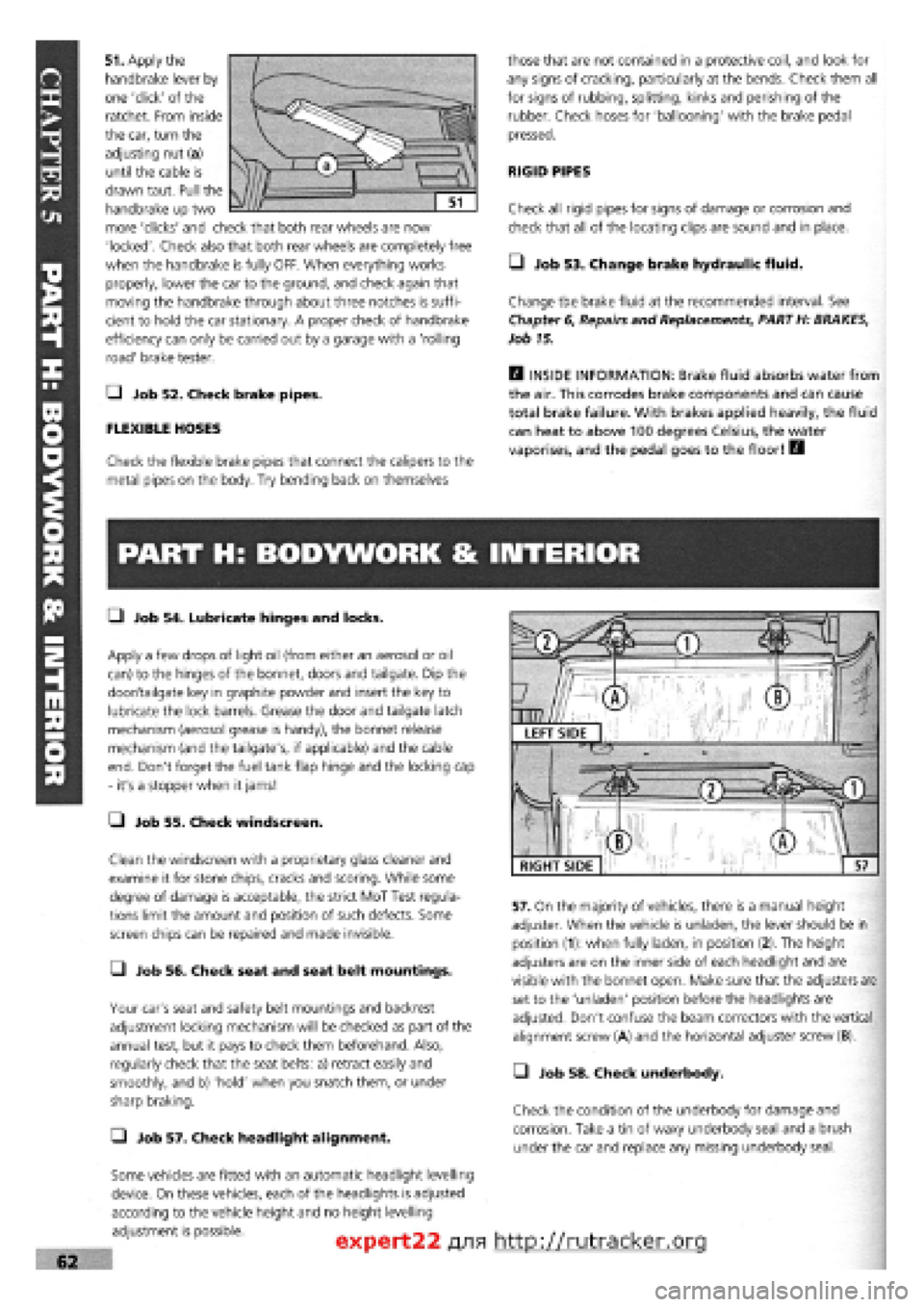
51. Apply the
handbrake lever by
one 'click' of the
ratchet. From inside
the car, turn the
adjusting nut (a)
until the cable is
drawn taut. Pull the
handbrake up two
more 'clicks' and check that both rear wheels are now
'locked'. Check also that both rear wheels are completely free
when the handbrake is fully OFF. When everything works
properly, lower the car to the ground, and check again that
moving the handbrake through about three notches is suffi-
cient to hold the car stationary. A proper check of handbrake
efficiency can only be carried out by a garage with a 'rolling
road' brake tester.
Q Job 52. Check brake pipes.
FLEXIBLE HOSES
Check the flexible brake pipes that connect the calipers to the
metal pipes on the body. Try bending back on themselves
those that are not contained in a protective coil, and look for
any signs of cracking, particularly at the bends. Check them all
for signs of rubbing, splitting, kinks and perishing of the
rubber. Check hoses for 'ballooning' with the brake pedal
pressed.
RIGID PIPES
Check all rigid pipes for signs of damage or corrosion and
check that all of the locating clips are sound and in place.
• Job 53. Change brake hydraulic fluid.
Change the brake fluid at the recommended interval. See
Chapter
6,
Repairs and Replacements, PART H: BRAKES,
Job 15.
H INSIDE INFORMATION: Brake fluid absorbs water from
the air. This corrodes brake components and can cause
total brake failure. With brakes applied heavily, the fluid
can heat to above 100 degrees Celsius, the water
vaporises, and the pedal goes to the floor! B
PART H: BODYWORK & INTERIOR
• Job 54. Lubricate hinges and locks.
Apply a few drops of light oil (from either an aerosol or oil
can) to the hinges of the bonnet, doors and tailgate. Dip the
door/tailgate key in graphite powder and insert the key to
lubricate the lock barrels. Grease the door and tailgate latch
mechanism (aerosol grease is handy), the bonnet release
mechanism (and the tailgate's, if applicable) and the cable
end. Don't forget the fuel tank flap hinge and the locking cap
- it's a stopper when it jams!
• Job 55. Check windscreen.
Clean the windscreen with a proprietary glass cleaner and
examine it for stone chips, cracks and scoring. While some
degree of damage is acceptable, the strict MoT Test regula-
tions limit the amount and position of such defects. Some
screen chips can be repaired and made invisible.
• Job 56. Check seat and seat belt mountings.
Your car's seat and safety belt mountings and backrest
adjustment locking mechanism will be checked as part of the
annual test, but it pays to check them beforehand. Also,
regularly check that the seat belts: a) retract easily and
smoothly, and b) 'hold' when you snatch them, or under
sharp braking.
Q Job 57. Check headlight alignment.
Some vehicles are fitted with an automatic headlight levelling
device. On these vehicles, each of the headlights is adjusted
according to the vehicle height and no height levelling
adjustment is possible.
57. On the majority of vehicles, there is a manual height
adjuster. When the vehicle is unladen, the lever should be in
position (1): when fully laden, in position (2). The height
adjusters are on the inner side of each headlight and are
visible with the bonnet open. Make sure that the adjusters are
set to the 'unladen' position before the headlights are
adjusted. Don't confuse the beam correctors with the vertical
alignment screw (A) and the horizontal adjuster screw (B).
• Job 58. Check underbody.
Check the condition of the underbody for damage and
corrosion. Take a tin of waxy underbody seal and a brush
under the car and replace any missing underbody seal.
expert22 fl/ia http://rutracker.org
RIGHT SIDE
Page 59 of 171
—1 Job 59. Check spare tyre.
This
job should ideally be carried out every month or two
-
you
never know when you're going to need that spare! But if you
haven't remembered, do it at the time shown on the Service
Interval Chart at the latest.
Q INSIDE INFORMATION: Put in the maximum recom-
mended pressure for heavy-duty use
-
it's always easier
to let some air out if necessary, than to put some in. Lift
the spare out check the 'hidden' lower side wall
for cracking. See Job 6. E9
PART I: ROAD TEST
Q Job 62. Road test and specialist check
-
after
every service.
Before you can claim to have 'finished' working on your car,
you must check it, test it, and, if necessary, have a qualified
mechanic check it over for you.
If you
are not a qualified mechanic, we strongly recommend
having someone who is a properly qualified mechanic
-
your
FIAT dealership perhaps
-
inspect all of the car's safety-related
items
after they have been worked on at home and before
using
the car on the road.
You'll have to remove the toolkit and the wheel to get at the
valve
-
under the boot floor on most models but to one side of
the rear compartment on Estate versions.
• Job 60. Change pollen filter.
When fitted to the fresh air intake, replace it at the scheduled
mileage interval.
• Job 61. Replace airbag gas generator.
Have your FIAT dealer replace the airbag gas generator 10
years after the car was built
-
see the label inside the car's
glove compartment door.
• Before setting out, check that the lights, indicators and in-
car controls, as well as seat belts and seat adjustments, all
work correctly.
• Run the car for several minutes before setting out then turn
off, check fluid levels and check underneath for leaks.
• Check that the steering moves freely in both directions and
that the car does not 'pull' one way or the other when driving
in a straight line
-
but do bear in mind the effect of the
camber on the road.
• Make sure that the brakes work effectively, smoothly and
without the need for 'pumping'. There should be no juddering
or squealing.
• Check that the car does not 'pull' from one side to the
other when you brake firmly from around 40 mph. (Don't
cause a skid and don't try this if there is any following traffic.)
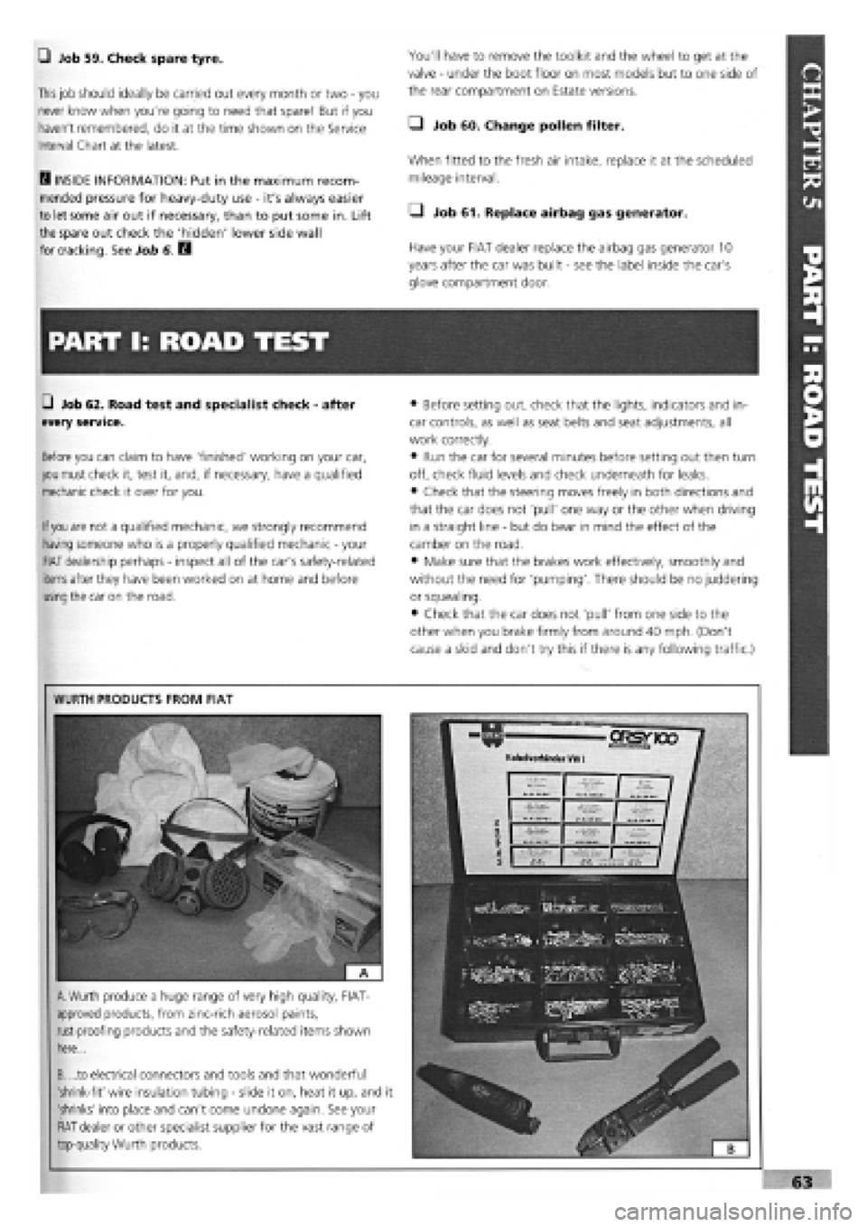
"V,
WURTH PRODUCTS FROM FIAT
A.
Wurth produce a huge range of very high quality, FIAT-
approved products, from zinc-rich aerosol paints,
rust-proofing products and the safety-related items shown
here...
B. ...to electrical connectors and tools and that wonderful
'shrink-fit' wire insulation tubing
-
slide it on, heat it up, and it
'shrinks' into place and can't come undone again. See your
FIAT dealer or other specialist supplier for the vast range of
top-quality Wurth products.
Page 75 of 171
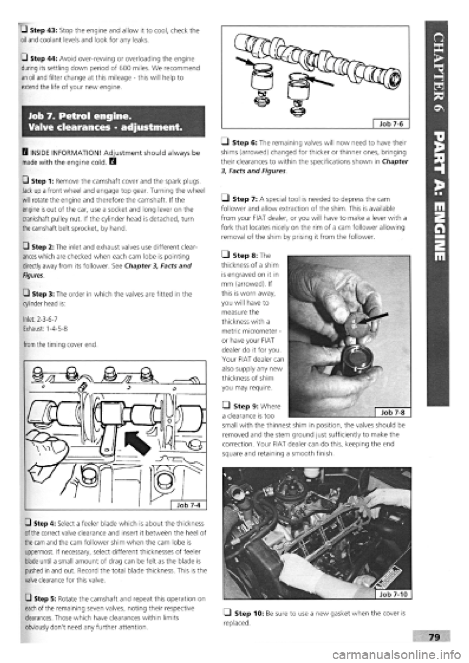
G Step 43: Stop the engine and allow it to cool, check the
oil
and coolant levels and look for any leaks.
G Step 44: Avoid over-rewing or overloading the engine
during its settling down period of 600 miles. We recommend
an oil
and filter change at this mileage
-
this will help to
extend the life of your new engine.
Job 7. Petrol engine.
Valve clearances - adjustment.
0 INSIDE INFORMATION! Adjustment should always be
made with the engine cold. B
G Step 1: Remove the camshaft cover and the spark plugs.
Jack up a front wheel and engage top gear. Turning the wheel
will rotate the engine and therefore the camshaft. If the
engine
is
out of the car, use a socket and long lever on the
crankshaft pulley nut. If the cylinder head is detached, turn
the
camshaft belt sprocket, by hand.
G Step 2: The inlet and exhaust valves use different clear-
ances
which are checked when each cam lobe is pointing
directly away from its follower. See Chapter
3,
Facts and
Figures.
G Step 3: The order in which the valves are fitted in the
cylinder head is:
Inlet: 2-3-6-7
Exhaust: 1-4-5-8
from
the timing cover end.
G Step 4: Select a feeler blade which is about the thickness
of the
correct valve clearance and insert it between the heel of
the cam
and the cam follower shim when the cam lobe is
uppermost. If necessary, select different thicknesses of feeler
blade until a small amount of drag can be felt as the blade is
pushed in and out. Record the total blade thickness. This is the
valve clearance for this valve.
G Step 5: Rotate the camshaft and repeat this operation on
each
of the remaining seven valves, noting their respective
clearances. Those which have clearances within limits
obviously don't need any further attention.
Q Step 6: The remaining valves will now need to have their
shims (arrowed) changed for thicker or thinner ones, bringing
their clearances to within the specifications shown in Chapter
3, Facts and Figures
Ll Step 7: A special tool is needed to depress the cam
follower and allow extraction of the shim. This is available
from your FIAT dealer, or you will have to make a lever with a
fork that locates nicely on the rim of a cam follower allowing
removal of the shim by prising it from the follower.
• Step 8: The
thickness of a shim
is engraved on it in
mm (arrowed). If
this is worn away,
you will have to
measure the
thickness with a
metric micrometer
-
or have your FIAT
dealer do it for you.
Your FIAT dealer can
also supply any new
thickness of shim
you may require.
• Step 9: Where
a clearance is too
small with the thinnest shim in position, the valves should be
removed and the stem ground just sufficiently to make the
correction. Your FIAT dealer can do this, keeping the end
square and retaining a smooth finish.
fjfefe^ | Job 7-10
Q Step 10: Be sure to use a new gasket when the cover is
replaced.
Page 79 of 171
Job 10. Petrol engine/
transmission (removed from car)
- separation.
Job 11. Petrol engine/
transmission (removed from car)
- reconnection.
• Clean the whole unit
with a proprietary
degreaser
-
and dry off
before
starting work.
•
This
makes these heavy components easier and safer
to
handle
and greatly reduces the risk of contami-
nation
when you strip them down.
Job 10-1
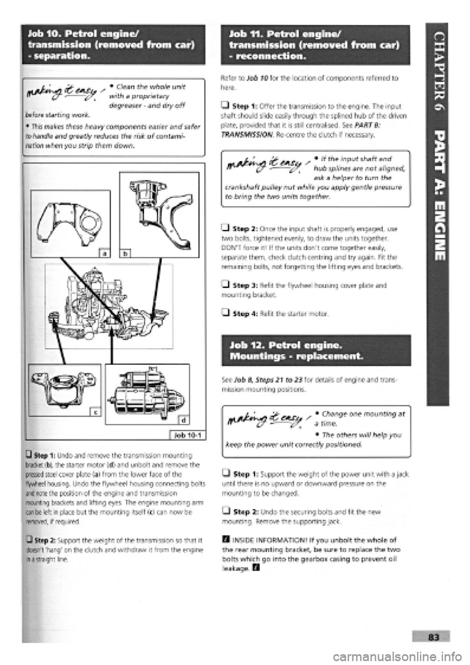
Q Step 1: Undo and remove the transmission mounting
bracket (b),
the starter motor (d) and unbolt and remove the
pressed
steel cover plate (a) from the lower face of the
flywheel housing. Undo the flywheel housing connecting bolts
and note
the position of the engine and transmission
mounting brackets and lifting eyes. The engine mounting arm
can be
left in place but the mounting itself (c) can now be
removed, if required.
Q Step 2: Support the weight of the transmission so that it
doesn't 'hang' on the clutch and withdraw it from the engine
in a
straight line.
Refer to Job
10
for the location of components referred to
here.
• Step 1: Offer the transmission to the engine. The input
shaft should slide easily through the splined hub of the driven
plate, provided that it is still centralised. See PART B:
TRANSMISSION Re-centre the clutch if necessary.
r ' «the input shaft and
- hub splines are not aligned,
ask a helper to turn the
crankshaft pulley nut while you apply gentle pressure
to bring the two units together.
• Step 2: Once the input shaft is properly engaged, use
two bolts, tightened evenly, to draw the units together.
DON'T force it! If the units don't come together easily,
separate them, check clutch centring and try again. Fit the
remaining bolts, not forgetting the lifting eyes and brackets.
• Step 3: Refit the flywheel housing cover plate and
mounting bracket.
Q Step 4: Refit the starter motor.
Job 12. Petrol engine.
Mountings - replacement.
See Job 8, Steps 21 to 23 for details of engine and trans-
mission mounting positions.
Change one mounting at
time.
• The others will help you
keep the power unit correctly positioned.
• Step 1: Support the weight of the power unit with a jack
until there is no upward or downward pressure on the
mounting to be changed.
Q Step 2: Undo the securing bolts and fit the new
mounting. Remove the supporting jack.
H INSIDE INFORMATION! If you unbolt the whole of
the rear mounting bracket, be sure to replace the two
bolts which go into the gearbox casing to prevent oil
leakage. D