differential FIAT TEMPRA 1988 Service And Repair Manual
[x] Cancel search | Manufacturer: FIAT, Model Year: 1988, Model line: TEMPRA, Model: FIAT TEMPRA 1988Pages: 171, PDF Size: 18.05 MB
Page 12 of 171
EMERGENCY STARTING
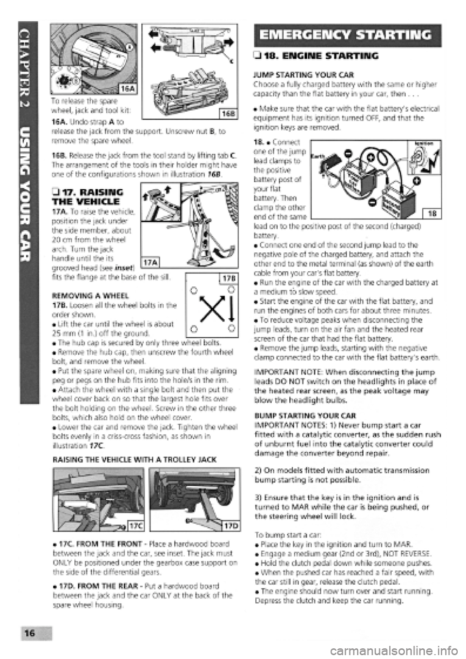
To release the spare
wheel, jack and tool kit:
16A. Undo strap A to
release the jack from the support. Unscrew nut B, to
remove the spare wheel.
16B. Release the jack from the tool stand by lifting tab C.
The arrangement of the tools in their holder might have
one of the configurations shown in illustration 16B.
• 17. RAISING
THE VEHICLE
17A. To raise the vehicle,
position the jack under
the side member, about
20 cm from the wheel
arch. Turn the jack
handle until the its
grooved head (see inset)
fits the flange at the base of the sill.
REMOVING A WHEEL
17B. Loosen all the wheel bolts in the
order shown.
• Lift the car until the wheel is about
25 mm
(1
in.) off the ground.
• The hub cap is secured by only three wheel bolts.
• Remove the hub cap, then unscrew the fourth wheel
bolt, and remove the wheel.
• Put the spare wheel on, making sure that the aligning
peg or pegs on the hub fits into the hole/s in the rim.
• Attach the wheel with a single bolt and then put the
wheel cover back on so that the largest hole fits over
the bolt holding on the wheel. Screw in the other three
bolts, which also hold on the wheel cover.
• Lower the car and remove the jack. Tighten the wheel
bolts evenly in a criss-cross fashion, as shown in
illustration 17C.
RAISING THE VEHICLE WITH A TROLLEY JACK
• 17C. FROM THE FRONT
-
Place a hardwood board
between the jack and the car, see inset. The jack must
ONLY be positioned under the gearbox case support on
the side of the differential gears.
• 17D. FROM THE REAR
-
Put a hardwood board
between the jack and the car ONLY at the back of the
spare wheel housing.
• 18. ENGINE STARTING
JUMP STARTING YOUR CAR
Choose a fully charged battery with the same or higher
capacity than the flat battery in your car, then ...
• Make sure that the car with the flat battery's electrical
equipment has its ignition turned OFF, and that the
ignition keys are removed.
18. • Connect
one of the jump
lead clamps to
the positive
battery post of
your flat
battery. Then
clamp the other
end of the same
lead on to the positive post of the second (charged)
battery.
• Connect one end of the second jump lead to the
negative pole of the charged battery, and attach the
other end to the metal terminal (as shown) of the earth
cable from your car's flat battery.
• Run the engine of the car with the charged battery at
a medium to slow speed.
• Start the engine of the car with the flat battery, and
run the engines of both cars for about three minutes.
• To reduce voltage peaks when disconnecting the
jump leads, turn on the air fan and the heated rear
screen of the car that had the flat battery.
• Remove the jump leads, starting with the negative
clamp connected to the car with the flat battery's earth.
IMPORTANT NOTE: When disconnecting the jump
leads DO NOT switch on the headlights in place of
the heated rear screen, as the peak voltage may
blow the headlight bulbs.
BUMP STARTING YOUR CAR
IMPORTANT NOTES: 1) Never bump start a car
fitted with a catalytic converter, as the sudden rush
of unburnt fuel into the catalytic converter could
damage the converter beyond repair.
2) On models fitted with automatic transmission
bump starting is not possible.
3) Ensure that the key is in the ignition and is
turned to MAR while the car is being pushed, or
the steering wheel will lock.
To bump start a car:
• Place the key in the ignition and turn to MAR.
• Engage a medium gear (2nd or 3rd), NOT REVERSE.
• Hold the clutch pedal down while someone pushes.
• When the pushed car has reached a fair speed, with
the car still in gear, release the clutch pedal.
• The engine should now turn over and start running.
Depress the clutch and keep the car running.
16
Page 20 of 171
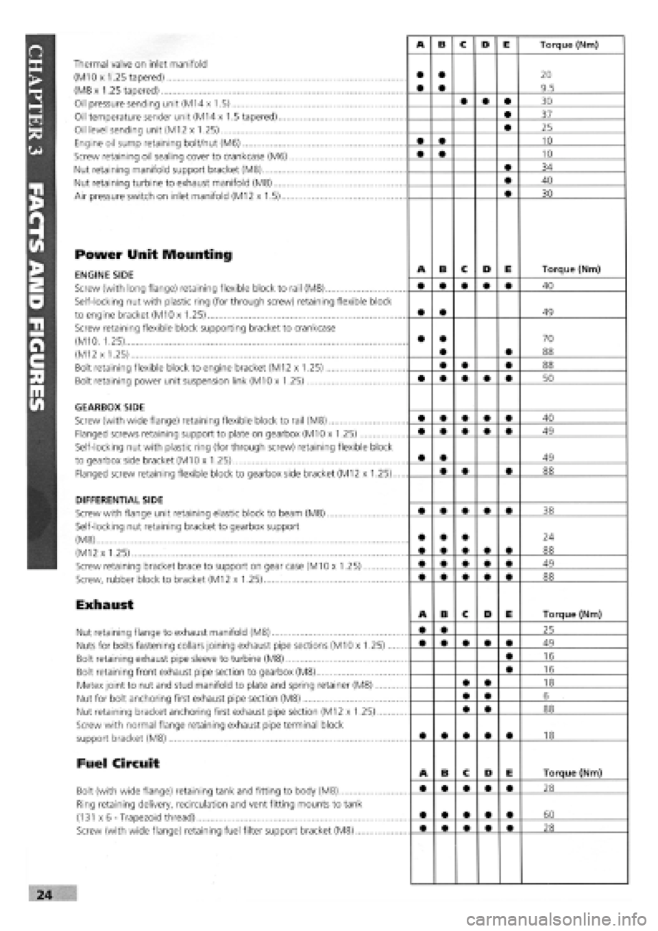
Thermal valve on inlet manifold
(M10 x 1.25 tapered)
(M8 x 1.25 tapered)
Oil pressure sending unit (M14 x 1.5)
Oil temperature sender unit (M14 x 1.5 tapered)....
Oil level sending unit (M12 x 1.25)
Engine oil sump retaining bolt/nut (M6)
Screw retaining oil sealing cover to crankcase (M6)
Nut retaining manifold support bracket (M8)
Nut retaining turbine to exhaust manifold (M8)
Air pressure switch on inlet manifold (M12 x 1.5)...
Power Unit Mounting
ENGINE SIDE
Screw (with long flange) retaining flexible block to rail (M8)
Self-locking nut with plastic ring (for through screw) retaining flexible block
to engine bracket (M10 x 1.25)
Screw retaining flexible block supporting bracket to crankcase
(M10. 1.25)
(M12 x 1.25)
Bolt retaining flexible block to engine bracket (M12 x 1.25)
Bolt retaining power unit suspension link (M10 x 1.25)
GEARBOX SIDE
Screw (with wide flange) retaining flexible block to rail (M8)
Flanged screws retaining support to plate on gearbox (M10 x 1.25)
Self-locking nut with plastic ring (for through screw) retaining flexible block
to gearbox side bracket (M10 x 1.25)
Flanged screw retaining flexible block to gearbox side bracket (M12 x 1.25).
DIFFERENTIAL SIDE
Screw with flange unit retaining elastic block to beam (M8)
Self-locking nut retaining bracket to gearbox support
(M8)
(M12 x 1.25)
Screw retaining bracket brace to support on gear case (M10 x 1.25)
Screw, rubber block to bracket (M12 x 1.25)
Exhaust
Nut retaining flange to exhaust manifold (M8)
Nuts for bolts fastening collars joining exhaust pipe sections (M10 x 1.25)...
Bolt retaining exhaust pipe sleeve to turbine (M8)
Bolt retaining front exhaust pipe section to gearbox (M8)
Metex joint to nut and stud manifold to plate and spring retainer (M8)
Nut for bolt anchoring first exhaust pipe section (M8)
Nut retaining bracket anchoring first exhaust pipe section (M12 x 1.25)
Screw with normal flange retaining exhaust pipe terminal block
support bracket (M8)
Fuel Circuit
Bolt (with wide flange) retaining tank and fitting to body (M8)
Ring retaining delivery, recirculation and vent fitting mounts to tank
(131 x 6-Trapezoid thread)
Screw (with wide flange) retaining fuel filter support bracket (M8)
Page 21 of 171
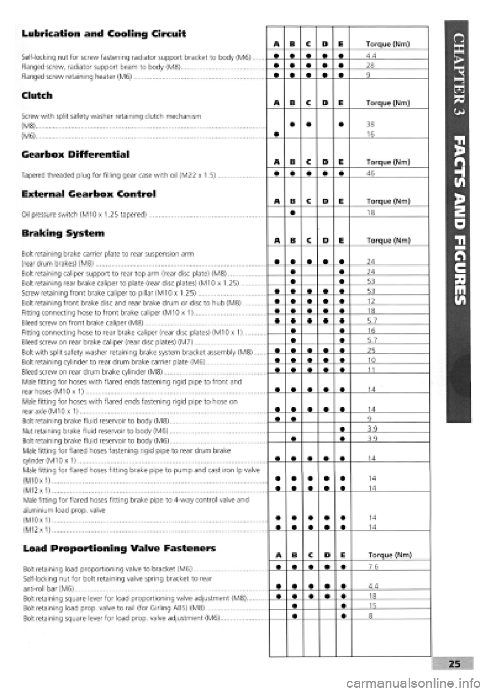
Lubrication and Cooling Circuit
Self-locking nut for screw fastening radiator support bracket to body (M6)....
Flanged screw, radiator support beam to body (M8)
Flanged screw retaining heater (M6)
Clutch
Screw with split safety washer retaining clutch mechanism
(M8)
(M6)
Gearbox Differential
Tapered threaded plug for filling gear case with oil (M22 x 1.5)
External Gearbox Control
Oil pressure switch (M10 x 1.25 tapered)
Braking System
Bolt retaining brake carrier plate to rear suspension arm
(rear drum brakes) (M8)
Bolt retaining caliper support to rear top arm (rear disc plate) (M8)
Bolt retaining rear brake caliper to plate (rear disc plates) (M10 x 1.25)
Screw retaining front brake caliper to pillar (M10 x 1.25)
Bolt retaining front brake disc and rear brake drum or disc to hub (M8)
Fitting connecting hose to front brake caliper (M10 x 1)
Bleed screw on front brake caliper (M8)
Fitting connecting hose to rear brake caliper (rear disc plates) (M10 x 1)
Bleed screw on rear brake caliper (rear disc plates) (M7)
Bolt with split safety washer retaining brake system bracket assembly (M8)....
Bolt retaining cylinder to rear drum brake carrier plate (M6)
Bleed screw on rear drum brake cylinder (M8)
Male fitting for hoses with flared ends fastening rigid pipe to front and
rear hoses (M10 x 1)
Male fitting for hoses with flared ends fastening rigid pipe to hose on
rear axle (M10 x 1)
Bolt retaining brake fluid reservoir to body (M8)
Nut retaining brake fluid reservoir to body (M6)
Bolt retaining brake fluid reservoir to body (M6)
Male fitting for flared hoses fastening rigid pipe to rear drum brake
cylinder
(M1
Ox 1)
Male fitting for flared hoses fitting brake pipe to pump and cast iron Ip valve
(M10
x
1)
(M12
x
1)
Male fitting for flared hoses fitting brake pipe to 4-way control valve and
aluminium load prop, valve
(M10 x
1)
(M12
x
1)
Load Proportioning Valve Fasteners
Bolt retaining load proportioning valve to bracket (M6)
Self-locking nut for bolt retaining valve spring bracket to rear
anti-roll bar (M6)
Bolt retaining square lever for load proportioning valve adjustment (M8)
Bolt retaining load prop, valve to rail (for Girling ABS) (M8)
Bolt retaining square lever for load prop, valve adjustment (M6)
Page 60 of 171
Please read the whole of CHAPTER
1,
SAFETY FIRST before carrying out any work on your car.
CHAPTER 6
REPAIRS AND REPLACEMENTS
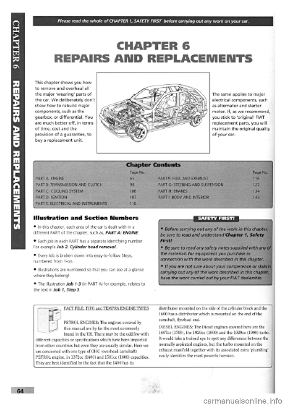
This chapter shows you how
to remove and overhaul all
the major 'wearing' parts of
the car. We deliberately don't
show how to rebuild major
components, such as the
gearbox, or differential. You
are much better off, in terms
of time, cost and the
provision of a guarantee, to
buy a replacement unit.
The same applies to major
electrical components, such
as alternator and starter
motor. If, as we recommend,
you stick to 'original' FIAT
replacement parts, you will
maintain the original quality
of your car.
PART A: ENGINE
PART B: TRANSMISSION AND CLUTCH
PART C: COOLING SYSTEM
PART D: IGNITION
PART E: ELECTRICAL AND INSTRUMENTS
:er Contents
PARTf: FUEL AND EXHAUST
PART G: STEERING AND SUSPENSION
PART H: BRAKES
PART I: BODY AND INTERIOR
110
Page No.
116
127
134
143
Illustration and Section Numbers
• In this chapter, each area of the car is dealt with in a
different PART of the chapter, such as, PART A: ENGINE.
• Each job in each PART has a separate identifying number.
For example Job 2. Cylinder head removal.
• Every Job is broken down into easy-to-follow Steps,
numbered from 1-on.
• Illustrations are numbered so that you can see at a glance
where they belong!
• The illustration Job
1-3
(in PART A) for example, relates to
the text in Job 1, Step 3.
SAFETY FIRST!
• Before carrying out any of the work in this chapter,
be sure to read and understand Chapter 1, Safety
First!
• Be sure to read any safety notes supplied with any
of
the materials for equipment you purchase in
connection with the work described in this chapter.
• If you are not sure about your competence or
skills in
carrying out any of the work described in this chapter,
have the work carried out by your FIAT dealership.
FACT FILE: TIPO and TEMPRA ENGINE TYPES
PETROL ENGINES: The engines covered by
this manual are by far the most commonly
found in the UK. There may be the odd few with
different capacities or specifications which have been imported
from other countries but even they are usually similar. Here we
are concerned with one type of OHC (overhead camshaft)
PETROL engine, in 1372cc (1400) and 1581cc (1600) capacities.
They are best identified by the fact that the 1400 has its
distributor mounted on the side of the cylinder block and the
1600 has a distributor which is mounted on the end of the
camshaft, flywheel end.
DIESEL ENGINES: The Diesel engines covered here are the
1697cc (1700), the 1929cc (1900) and the 1929cc (1900) turbo.
It would take a trained eye to spot any differences between the
normally aspirated engines, but the turbo mounted on the
exhaust manifold together with its associated extra 'plumbing'
easily identifies the most powerful version.
Page 150 of 171
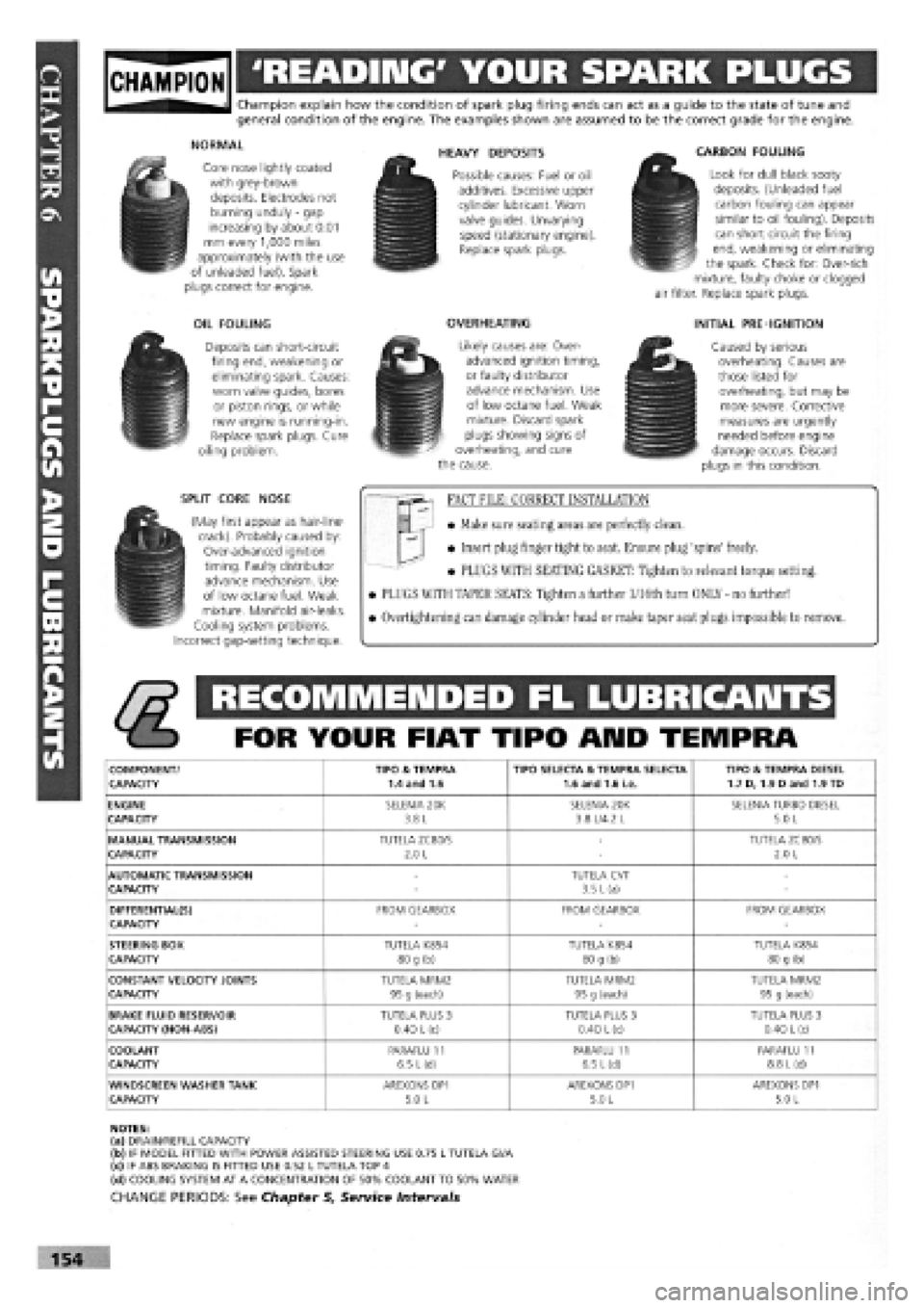
gjpjgjjl 'READING' YOUR SPARK PLUGS
Champion explain how the condition of spark plug firing ends can act as a guide to the state of tune and general condition of the engine. The examples shown are assumed to be the correct grade for the engine.
NORMAL
Core nose lightly coated with grey-brown deposits. Electrodes not burning unduly
-
gap increasing by about 0.01 mm every 1,000 miles approximately (with the use of unleaded fuel). Spark plugs correct for engine.
OIL FOULING
Deposits can short-circuit firing end, weakening or eliminating spark. Causes: worn valve guides, bores or piston rings, or while new engine is running-in. Replace spark plugs. Cure oiling problem.
SPLIT CORE NOSE
(May first appear as hair-line-crack). Probably caused by: Over-advanced ignition timing. Faulty distributor advance mechanism. Use of low octane fuel. Weak mixture. Manifold air-leaks. Cooling system problems. Incorrect gap-setting technique.
HEAVY DEPOSITS
Possible causes: Fuel or oil additives. Excessive upper cylinder lubricant. Worn valve guides. Unvarying speed (stationary engine). Replace spark plugs.
OVERHEATING
Likely causes are: Over-advanced ignition timing, or faulty distributor advance mechanism. Use of low octane fuel. Weak mixture. Discard spark plugs showing signs of overheating, and cure the cause.
CARBON FOULING
Look for dull black sooty deposits. (Unleaded fuel carbon fouling can appear similar to oil fouling). Deposits can short circuit the firing end, weakening or eliminating the spark. Check for: Over-rich mixture, faulty choke or clogged air filter. Replace spark plugs.
INITIAL PRE-IGNITION
Caused by serious overheating. Causes are those listed for overheating, but may be more severe. Corrective measures are urgently needed before engine damage occurs. Discard plugs in this condition.
FACT FILE: CORRECT INSTALLATION
• Make sure seating areas are perfectly clean.
• Insert plug finger tight to seat. Ensure plug 'spins' freely.
• PLUGS WITH SEATING GASKET: Tighten to relevant torque setting.
• PLUGS WITH TAPER SEATS: Tighten a further l/16th turn ONLY - no further!
• Overtightening can damage cylinder head or make taper seat plugs impossible to remove.
RECOMMENDED FL LUBRICANTS
FOR YOUR FIAT TIPO ARID TEMPRA
COMPONENT/ TIPO & TEMPRA TIPO SELECTA & TEMPRA SELECTA TIPO & TEMPRA DIESEL CAPACITY 1.4 and 1.6 1.6 and 1.6 i.e. 1.7 D, 1.9 Dand 1.9 TD
ENGINE SELENIA 20K SELENIA 20K SELENIA TURBO DIESEL CAPACITY 3.8 L 3.8 L/4.2 L 5.0 L
MANUAL TRANSMISSION TUTELA ZC80/S -TUTELA ZC80/S CAPACITY 2.0 L -2.0 L
AUTOMATIC TRANSMISSION -TUTELA CVT -CAPACITY -3.5 L (a) -
DIFFERENTIAL(S) FROM GEARBOX FROM GEARBOX FROM GEARBOX CAPACITY ---
STEERING BOX TUTELA K854 TUTELA K854 TUTELA K854 CAPACITY 80 g (b) 80 g (b) 80 g (b)
CONSTANT VELOCITY JOINTS TUTELA MRM2 TUTELA MRM2 TUTELA MRM2 CAPACITY 95 g (each) 95 g (each) 95 g (each)
BRAKE FLUID RESERVOIR TUTELA PLUS 3 TUTELA PLUS 3 TUTELA PLUS 3 CAPACITY (NON-ABS) 0.40
L
(c) 0.40 L (c) 0.40
L
(c)
COOLANT PARAFLU 11 PARAFLU 11 PARAFLU 11 CAPACITY 6.5 L(d) 6.5 L(d) 8.8
L
(d)
WINDSCREEN WASHER TANK AREXONS DP1 AREXONS DP1 AREXONS DP1 CAPACITY 5.0 L 5.0 L 5.0 L
NOTES: (a) DRAIN/REFILL CAPACITY (b) IF MODEL FITTED WITH POWER ASSISTED STEERING USE 0.75 L TUTELA Gl/A (c) IF ABS BRAKING IS FITTED USE 0.52 L TUTELA TOP 4 (d) COOLING SYSTEM AT A CONCENTRATION OF 50% COOLANT TO 50% WATER
CHANGE PERIODS: See Chapter 5, Service Intervals
154