mileage FIAT TEMPRA 1988 Service And Repair Manual
[x] Cancel search | Manufacturer: FIAT, Model Year: 1988, Model line: TEMPRA, Model: FIAT TEMPRA 1988Pages: 171, PDF Size: 18.05 MB
Page 29 of 171
Thanks
are due to the excellent, knowledgeable and helpful staff at FIAT main dealers, Ryauto of Amblecote, in the West
Midlands for supplying vehicles and for their assistance with this chapter. In particular, thanks are due to the efficient Maurice
Hough, Service Manager, the experienced Foreman, Tony Morris, and young demon mechanic, Matthew Worsfold.
Some of the suggested inspection/replacement intervals may not correspond to those shown in the original handbook. The suggested
schedule, based on FIAT'S recommendations, takes into account the age of the vehicle and the annual MoT test in the UK.
In practice, because of the split between (mainly) 12 month/9,000 mile and 18 month/13,500 mile intervals, you will need to
service your Tipo or Tempra at most, if not every, 6 month interval.
IMPORTANT NOTE: Each service should be carried out at EITHER the recommended mileage OR the recommended time
interval, whichever comes first.
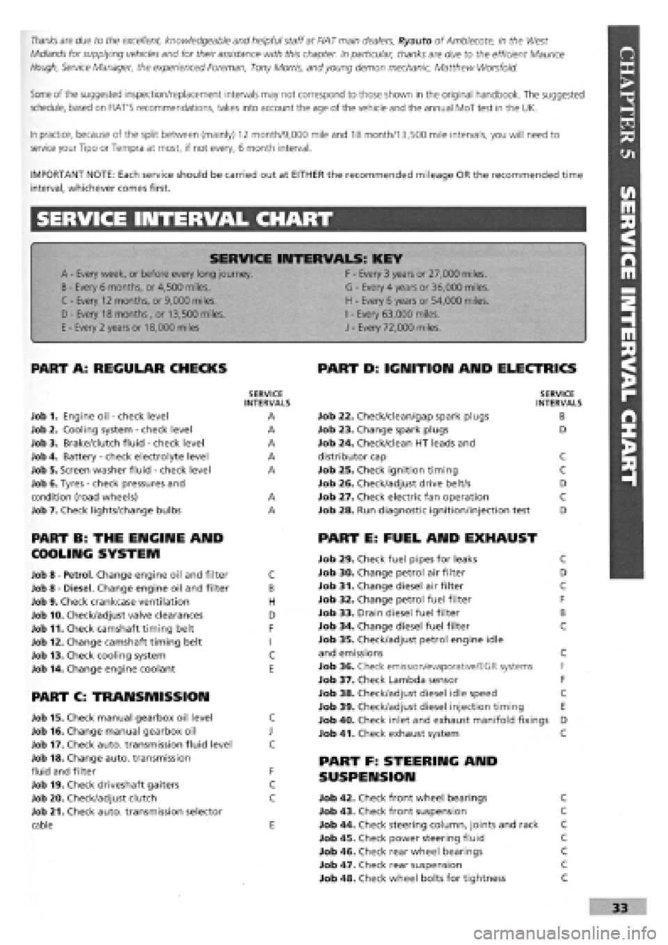
SERVICE INTERVAL CHART
SERVICE INTERVALS: KEY
A
-
Every week, or before every long journey. F
-
Every 3 years or 27,000 miles.
B
-
Every 6 months, or 4,500 miles. G
-
Every 4 years or 36,000 miles.
C - Every 12 months, or 9,000 miles. H
-
Every 6 years or 54,000 miles.
I
-
Every 63,000 miles. D - Every 18 months , or 13,500 miles.
H
-
Every 6 years or 54,000 miles.
I
-
Every 63,000 miles.
E
-
Every 2 years or 18,000 miles J
-
Every 72,000 miles.
PART A: REGULAR CHECKS
SERVICE INTERVALS
Job 1. Engine oil
-
check level A
Job 2. Cooling system
-
check level A
Job 3. Brake/clutch fluid
-
check level A
Job 4. Battery
-
check electrolyte level A
Job 5. Screen washer fluid
-
check level A
Job 6. Tyres
-
check pressures and
condition (road wheels) A
Job 7. Check lights/change bulbs A
PART B: THE ENGINE AND
COOLING SYSTEM
Job 8
-
Petrol. Change engine oil and filter C
Job 8
-
Diesel. Change engine oil and filter B
Job 9. Check crankcase ventilation H
Job 10. Check/adjust valve clearances D
Job 11. Check camshaft timing belt F
Job 12. Change camshaft timing belt I
Job 13. Check cooling system C
Job 14. Change engine coolant E
PART C: TRANSMISSION
Job 15. Check manual gearbox oil level C
Job 16. Change manual gearbox oil J
Job 17. Check auto, transmission fluid level C
Job 18. Change auto, transmission
fluid and filter F
Job 19. Check driveshaft gaiters C
Job 20. Check/adjust clutch C
Job 21. Check auto, transmission selector
cable E
PART D: IGNITION AND ELECTRICS
SERVICE INTERVALS
Job 22. Check/clean/gap spark plugs B
Job 23. Change spark plugs D
Job 24. Check/clean HT leads and
distributor cap C
Job 25. Check ignition timing C
Job 26. Check/adjust drive belt/s D
Job 27. Check electric fan operation C
Job 28. Run diagnostic ignition/injection test D
PART E: FUEL AND EXHAUST
Job 29. Check fuel pipes for leaks C
Job 30. Change petrol air filter D
Job 31. Change diesel air filter C
Job 32. Change petrol fuel filter F
Job 33. Drain diesel fuel filter B
Job 34. Change diesel fuel filter C
Job 35. Check/adjust petrol engine idle
and emissions C
Job 36. Check emission/evaporative/EGR systems F
Job 37. Check Lambda sensor F
Job 38. Check/adjust diesel idle speed C
Job 39. Check/adjust diesel injection timing E
Job 40. Check inlet and exhaust manifold fixings D
Job 41. Check exhaust system C
PART F: STEERING AND
SUSPENSION
Job 42. Check front wheel bearings C
Job 43. Check front suspension C
Job 44. Check steering column, joints and rack C
Job 45. Check power steering fluid C
Job 46. Check rear wheel bearings C
Job 47. Check rear suspension C
Job 48. Check wheel bolts for tightness C
Page 59 of 171
—1 Job 59. Check spare tyre.
This
job should ideally be carried out every month or two
-
you
never know when you're going to need that spare! But if you
haven't remembered, do it at the time shown on the Service
Interval Chart at the latest.
Q INSIDE INFORMATION: Put in the maximum recom-
mended pressure for heavy-duty use
-
it's always easier
to let some air out if necessary, than to put some in. Lift
the spare out check the 'hidden' lower side wall
for cracking. See Job 6. E9
PART I: ROAD TEST
Q Job 62. Road test and specialist check
-
after
every service.
Before you can claim to have 'finished' working on your car,
you must check it, test it, and, if necessary, have a qualified
mechanic check it over for you.
If you
are not a qualified mechanic, we strongly recommend
having someone who is a properly qualified mechanic
-
your
FIAT dealership perhaps
-
inspect all of the car's safety-related
items
after they have been worked on at home and before
using
the car on the road.
You'll have to remove the toolkit and the wheel to get at the
valve
-
under the boot floor on most models but to one side of
the rear compartment on Estate versions.
• Job 60. Change pollen filter.
When fitted to the fresh air intake, replace it at the scheduled
mileage interval.
• Job 61. Replace airbag gas generator.
Have your FIAT dealer replace the airbag gas generator 10
years after the car was built
-
see the label inside the car's
glove compartment door.
• Before setting out, check that the lights, indicators and in-
car controls, as well as seat belts and seat adjustments, all
work correctly.
• Run the car for several minutes before setting out then turn
off, check fluid levels and check underneath for leaks.
• Check that the steering moves freely in both directions and
that the car does not 'pull' one way or the other when driving
in a straight line
-
but do bear in mind the effect of the
camber on the road.
• Make sure that the brakes work effectively, smoothly and
without the need for 'pumping'. There should be no juddering
or squealing.
• Check that the car does not 'pull' from one side to the
other when you brake firmly from around 40 mph. (Don't
cause a skid and don't try this if there is any following traffic.)
"V,
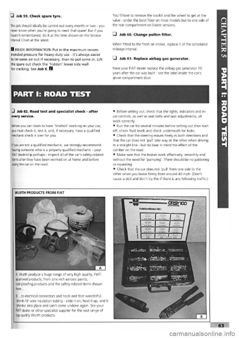
WURTH PRODUCTS FROM FIAT
A.
Wurth produce a huge range of very high quality, FIAT-
approved products, from zinc-rich aerosol paints,
rust-proofing products and the safety-related items shown
here...
B. ...to electrical connectors and tools and that wonderful
'shrink-fit' wire insulation tubing
-
slide it on, heat it up, and it
'shrinks' into place and can't come undone again. See your
FIAT dealer or other specialist supplier for the vast range of
top-quality Wurth products.
Page 75 of 171
G Step 43: Stop the engine and allow it to cool, check the
oil
and coolant levels and look for any leaks.
G Step 44: Avoid over-rewing or overloading the engine
during its settling down period of 600 miles. We recommend
an oil
and filter change at this mileage
-
this will help to
extend the life of your new engine.
Job 7. Petrol engine.
Valve clearances - adjustment.
0 INSIDE INFORMATION! Adjustment should always be
made with the engine cold. B
G Step 1: Remove the camshaft cover and the spark plugs.
Jack up a front wheel and engage top gear. Turning the wheel
will rotate the engine and therefore the camshaft. If the
engine
is
out of the car, use a socket and long lever on the
crankshaft pulley nut. If the cylinder head is detached, turn
the
camshaft belt sprocket, by hand.
G Step 2: The inlet and exhaust valves use different clear-
ances
which are checked when each cam lobe is pointing
directly away from its follower. See Chapter
3,
Facts and
Figures.
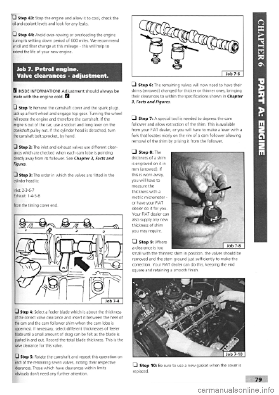
G Step 3: The order in which the valves are fitted in the
cylinder head is:
Inlet: 2-3-6-7
Exhaust: 1-4-5-8
from
the timing cover end.
G Step 4: Select a feeler blade which is about the thickness
of the
correct valve clearance and insert it between the heel of
the cam
and the cam follower shim when the cam lobe is
uppermost. If necessary, select different thicknesses of feeler
blade until a small amount of drag can be felt as the blade is
pushed in and out. Record the total blade thickness. This is the
valve clearance for this valve.
G Step 5: Rotate the camshaft and repeat this operation on
each
of the remaining seven valves, noting their respective
clearances. Those which have clearances within limits
obviously don't need any further attention.
Q Step 6: The remaining valves will now need to have their
shims (arrowed) changed for thicker or thinner ones, bringing
their clearances to within the specifications shown in Chapter
3, Facts and Figures
Ll Step 7: A special tool is needed to depress the cam
follower and allow extraction of the shim. This is available
from your FIAT dealer, or you will have to make a lever with a
fork that locates nicely on the rim of a cam follower allowing
removal of the shim by prising it from the follower.
• Step 8: The
thickness of a shim
is engraved on it in
mm (arrowed). If
this is worn away,
you will have to
measure the
thickness with a
metric micrometer
-
or have your FIAT
dealer do it for you.
Your FIAT dealer can
also supply any new
thickness of shim
you may require.
• Step 9: Where
a clearance is too
small with the thinnest shim in position, the valves should be
removed and the stem ground just sufficiently to make the
correction. Your FIAT dealer can do this, keeping the end
square and retaining a smooth finish.
fjfefe^ | Job 7-10
Q Step 10: Be sure to use a new gasket when the cover is
replaced.
Page 94 of 171
U Step 12: Fit a new seal to the front cover/oil pump
assembly, unless a new pump is being fitted, and install with a
new gasket, lightly oiling both gasket and seal. Align the cover
with the sump support plate.
PISTON CONNECTING RODS ASSEMBLIES
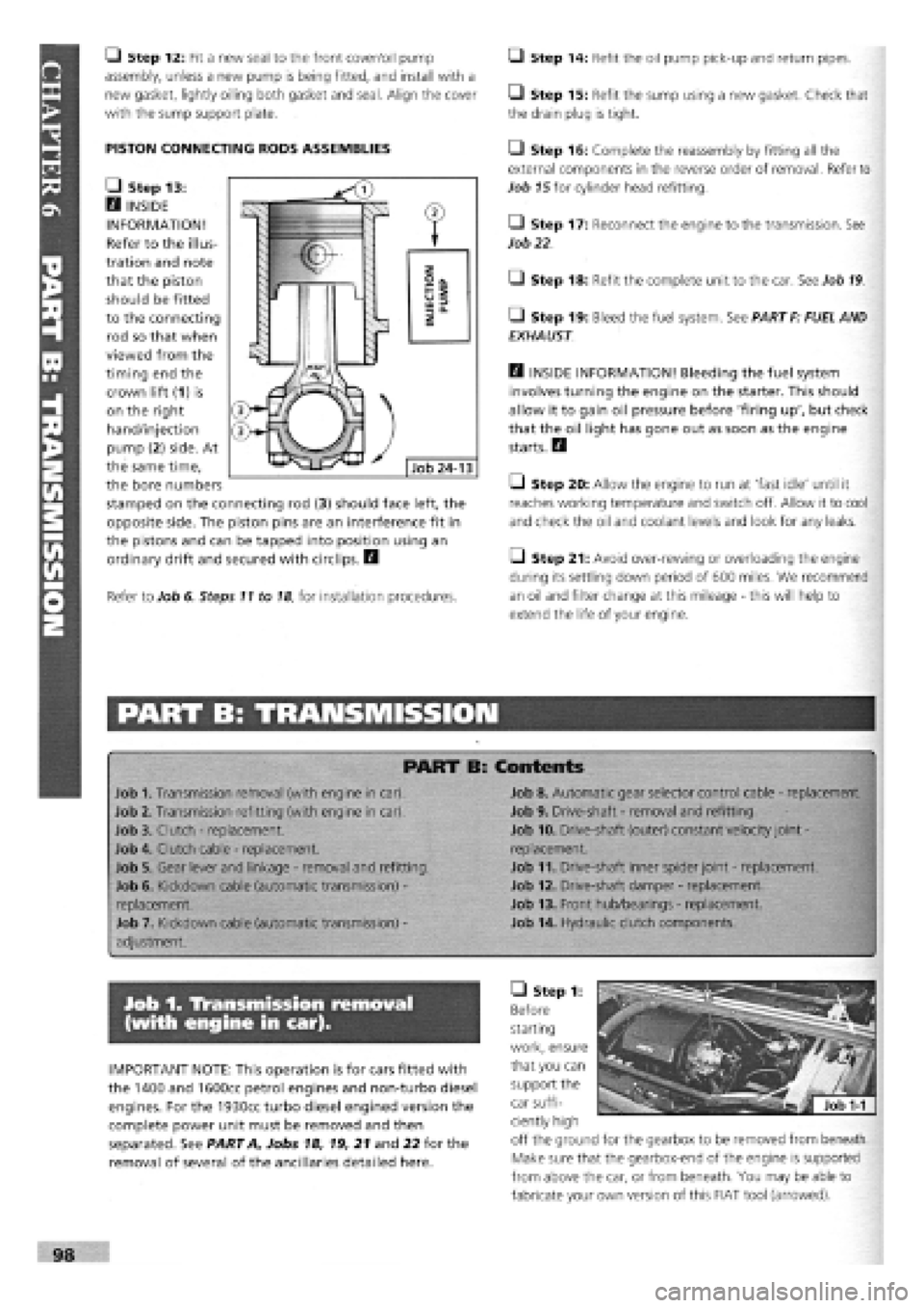
• Step 13:
H INSIDE
INFORMATION!
Refer to the illus-
tration and note
that the piston
should be fitted
to the connecting
rod so that when
viewed from the
timing end the
crown lift (1) is
on the right
hand/injection
pump (2) side. At
the same time,
the bore numbers
stamped on the connecting rod (3) should face left, the
opposite side. The piston pins are an interference fit in
the pistons and can be tapped into position using an
ordinary drift and secured with circlips. H
Refer to Job 6. Steps 11 to
18,
for installation procedures.
Q Step 14: Refit the oil pump pick-up and return pipes.
• Step 15: Refit the sump using a new gasket. Check that
the drain plug is tight.
• Step 16: Complete the reassembly by fitting all the
external components in the reverse order of removal. Refer to
Job
15
for cylinder head refitting.
• Step 17: Reconnect the engine to the transmission. See
Job
22
• Step 18: Refit the complete unit to the car. See Job
19
• Step 19: Bleed the fuel system. See PART F: FUEL AND
EXHAUST
Q INSIDE INFORMATION! Bleeding the fuel system
involves turning the engine on the starter. This should
allow it to gain oil pressure before 'firing up', but check
that the oil light has gone out as soon as the engine
starts. H
Q Step 20: Allow the engine to run at 'fast idle' until it
reaches working temperature and switch off. Allow it to cool
and check the oil and coolant levels and look for any leaks.
Q Step 21: Avoid over-rewing or overloading the engine
during its settling down period of 600 miles. We recommend
an oil and filter change at this mileage
-
this will help to
extend the life of your engine.
PART B: TRANSMISSION
PART B: Contents
Job 1. Transmission removal (with engine in car).
Job 2. Transmission refitting (with engine in car).
Job 3. Clutch
-
replacement.
Job 4. Clutch cable
-
replacement.
Job 5. Gear lever and linkage
-
removal and refitting.
Job 6. Kickdown cable (automatic transmission)
-
replacement.
Job 7. Kickdown cable (automatic transmission)
-
adjustment.
Job 8. Automatic gear selector control cable
-
replacement.
Job 9. Drive-shaft
-
removal and refitting.
Job 10. Drive-shaft (outer) constant velocity joint
-
replacement.
Job 11. Drive-shaft inner spider joint
-
replacement.
Job 12. Drive-shaft damper
-
replacement.
Job 13. Front hub/bearings
-
replacement.
Job 14. Hydraulic clutch components.
Job 1. Transmission removal
(with engine in car).
IMPORTANT NOTE: This operation is for cars fitted with
the 1400 and 1600cc petrol engines and non-turbo diesel
engines. For the 1930cc turbo diesel engined version the
complete power unit must be removed and then
separated. See PART A, Jobs 18, 19, 21 and 22 for the
removal of several of the ancillaries detailed here.
• Step 1:
Before
starting
work, ensure
that you can
support the
car suffi-
ciently high
off the ground for the gearbox to be removed from beneath.
Make sure that the gearbox-end of the engine is supported
from above the car, or from beneath. You may be able to
fabricate your own version of this FIAT tool (arrowed).
Page 96 of 171
• Step 4: Refill the gearbox with the correct grade and
quantity of FL oil. See Chapter
3,
Facts and Figures.
Section as appropriate, for the replacement of the rear
crankshaft seal. B
—1 Step 5: When the brake calipers have been refitted,
pump the brake pedal until its normal solid feel is restored.
• Step 6: Use a self-grip wrench to reconnect the gear rod
balls and sockets. Use new drive-shaft nuts, tightened to the
correct torque and staked into the shaft grooves with a
punch. See Job 9.
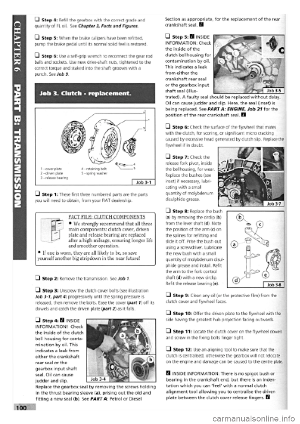
Job 3. Clutch - replacement.
1 - cover plate 2 - driven plate 3 - release bearing
4 - retaining bolt 5 - spring washer
;
Job 3-1
Q Step 1: These first three numbered parts are the parts
you will need to obtain, from your FIAT dealership.
FACT FILE: CLUTCH COMPONENTS
• We strongly recommend that all three
main components: clutch cover, driven
plate and release bearing are replaced
after a high mileage, ensuring longer life
and smoother operation.
• If one is worn, they are all likely to be, so save
yourself another big stripdown in the near future!
LI Step 2: Remove the transmission. See Job 1.
• Step 3: Unscrew the clutch cover bolts (see illustration
Job
3-1,
part 4) progressively until the spring pressure is
released, then remove the bolts. Ease the cover (part 1) off its
dowels and catch the driven plate {part 2) as it falls.
• Step 6: Check the surface of the flywheel that mates
with the clutch, for scoring, or significant micro cracking
caused by excessive head generated by clutch slip. Replace the
flywheel if in doubt.
7ZJ
• Step 7: Check the
release fork pivot, inside
the bellhousing, for wear
Replace the bushes (see
inset) if necessary, lubri-
cating with a small
quantity of molybdenum
disulphide grease.
• Step 8: Replace the bush
(a) by removing the circlip (b)
from the lever shaft (d). Note
the position of the arm (c) on
the splines for refitting and
slide it off. Prise the bush out
using a screwdriver. Lubricate
the new bush with a small
quantity of molybdenum disul-
phide grease and install. Refit
the arm to the fork control
shaft (d) with a new circlip.
Refit the release bearing (e).
• Step 9: Clean any oil (or the protective film) from the
clutch cover and flywheel faces.
• Step 10: Offer the driven plate to the flywheel with the
side having the greatest hub projection facing outwards.
• Step 11: Locate the clutch cover on the flywheel dowels
and screw in the fixing bolts finger tight.
• Step 12: Use an aligning tool to make sure that the
clutch is centralised, otherwise the gearbox will not relocate
on the engine and damage can be caused to the centre plate.
B INSIDE INFORMATION: There is no spigot bush or
bearing in the crankshaft end, but there is an inden-
tation which you can 'feel' with a normal clutch
alignment tool allowing you to centralise the driven
plate between the clutch cover release fingers. B
• Step 5: B INSIDE
INFORMATION: Check
the inside of the
clutch bellhousing for
contamination by oil.
This indicates a leak
from either the
crankshaft rear seal
or the gearbox input
shaft seal (illus-
trated). A faulty seal should be replaced without delay.
Oil can cause judder and slip. Here, the seal (inset) is
being replaced. See PART A: ENGINE, Job 21 for the
position of the rear crankshaft seal. B
• Step 4: B INSIDE
INFORMATION! Check
the inside of the clutch
bell housing for conta-
mination by oil. This
indicates a leak from
either the crankshaft
rear seal or the
gearbox input shaft
seal. Oil can cause
judder and slip.
Replace the gearbox seal by removing the screws holding
in the thrust bearing sleeve (a), prising out the old and
fitting a new seal (b). See PART A: Petrol or Diesel