service interval FIAT TEMPRA 1988 Service And Repair Manual
[x] Cancel search | Manufacturer: FIAT, Model Year: 1988, Model line: TEMPRA, Model: FIAT TEMPRA 1988Pages: 171, PDF Size: 18.05 MB
Page 28 of 171
Please read the whole of the Introduction to this Chapter before carrying out any work on your car.
CHAPTER 5
SERVICING YOUR CAR
Everyone wants to own a
car that starts first time,
runs reliably and lasts
longer than the average.
And it's all a question of
thorough maintenance!
If you follow the FIAT-
approved Service Jobs
listed here you can almost
guarantee that your car will
still be going strong when
others have fallen by the
wayside
-
or the hard
shoulder.
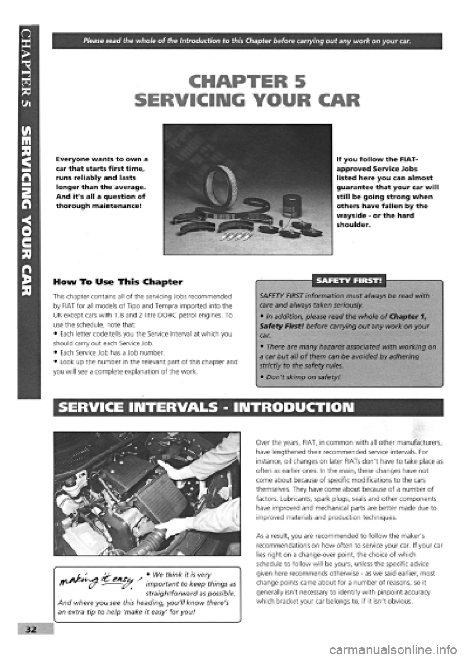
How To Use This Chapter
This chapter contains all of the servicing Jobs recommended
by FIAT for all models of Tipo and Tempra imported into the
UK except cars with 1.8 and 2 litre DOHC petrol engines. To
use the schedule, note that:
• Each letter code tells you the Service Interval at which you
should carry out each Service Job.
• Each Service Job has a Job number.
• Look up the number in the relevant part of this chapter and
you will see a complete explanation of the work.
SAFETY FIRST!
SAFETY FIRST information must always be read with
care and always taken seriously.
• In addition, please read the whole of Chapter 1,
Safety First! before carrying out any work on your
car.
• There are many hazards associated with working on
a car but all of them can be avoided by adhering
strictly to the safety rules.
• Don't skimp on safety!
SERVICE INTERVALS - INTRODUCTION
• We think it is very
important to keep things as
straightforward as possible.
And where you see this heading, you'll know there's
an extra tip to help 'make it easy' for you!
Over the years, FIAT, in common with all other manufacturers,
have lengthened their recommended service intervals. For
instance, oil changes on later FIATs don't have to take place as
often as earlier ones. In the main, these changes have not
come about because of specific modifications to the cars
themselves. They have come about because of a number of
factors: Lubricants, spark plugs, seals and other components
have improved and mechanical parts are better made due to
improved materials and production techniques.
As a result, you are recommended to follow the maker's
recommendations on how often to service your car. If your car
lies right on a change-over point, the choice of which
schedule to follow will be yours, unless the specific advice
given here recommends otherwise
-
as we said earlier, most
change points came about for a number of reasons, so it
generally isn't necessary to identify with pinpoint accuracy
which bracket your car belongs to, if it isn't obvious.
32
Page 29 of 171
Thanks
are due to the excellent, knowledgeable and helpful staff at FIAT main dealers, Ryauto of Amblecote, in the West
Midlands for supplying vehicles and for their assistance with this chapter. In particular, thanks are due to the efficient Maurice
Hough, Service Manager, the experienced Foreman, Tony Morris, and young demon mechanic, Matthew Worsfold.
Some of the suggested inspection/replacement intervals may not correspond to those shown in the original handbook. The suggested
schedule, based on FIAT'S recommendations, takes into account the age of the vehicle and the annual MoT test in the UK.
In practice, because of the split between (mainly) 12 month/9,000 mile and 18 month/13,500 mile intervals, you will need to
service your Tipo or Tempra at most, if not every, 6 month interval.
IMPORTANT NOTE: Each service should be carried out at EITHER the recommended mileage OR the recommended time
interval, whichever comes first.
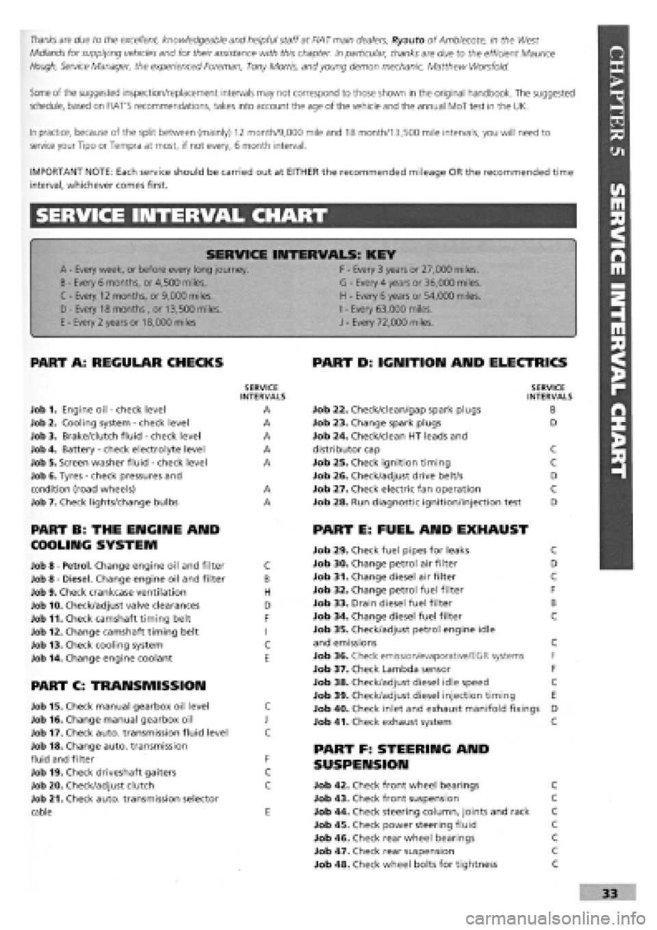
SERVICE INTERVAL CHART
SERVICE INTERVALS: KEY
A
-
Every week, or before every long journey. F
-
Every 3 years or 27,000 miles.
B
-
Every 6 months, or 4,500 miles. G
-
Every 4 years or 36,000 miles.
C - Every 12 months, or 9,000 miles. H
-
Every 6 years or 54,000 miles.
I
-
Every 63,000 miles. D - Every 18 months , or 13,500 miles.
H
-
Every 6 years or 54,000 miles.
I
-
Every 63,000 miles.
E
-
Every 2 years or 18,000 miles J
-
Every 72,000 miles.
PART A: REGULAR CHECKS
SERVICE INTERVALS
Job 1. Engine oil
-
check level A
Job 2. Cooling system
-
check level A
Job 3. Brake/clutch fluid
-
check level A
Job 4. Battery
-
check electrolyte level A
Job 5. Screen washer fluid
-
check level A
Job 6. Tyres
-
check pressures and
condition (road wheels) A
Job 7. Check lights/change bulbs A
PART B: THE ENGINE AND
COOLING SYSTEM
Job 8
-
Petrol. Change engine oil and filter C
Job 8
-
Diesel. Change engine oil and filter B
Job 9. Check crankcase ventilation H
Job 10. Check/adjust valve clearances D
Job 11. Check camshaft timing belt F
Job 12. Change camshaft timing belt I
Job 13. Check cooling system C
Job 14. Change engine coolant E
PART C: TRANSMISSION
Job 15. Check manual gearbox oil level C
Job 16. Change manual gearbox oil J
Job 17. Check auto, transmission fluid level C
Job 18. Change auto, transmission
fluid and filter F
Job 19. Check driveshaft gaiters C
Job 20. Check/adjust clutch C
Job 21. Check auto, transmission selector
cable E
PART D: IGNITION AND ELECTRICS
SERVICE INTERVALS
Job 22. Check/clean/gap spark plugs B
Job 23. Change spark plugs D
Job 24. Check/clean HT leads and
distributor cap C
Job 25. Check ignition timing C
Job 26. Check/adjust drive belt/s D
Job 27. Check electric fan operation C
Job 28. Run diagnostic ignition/injection test D
PART E: FUEL AND EXHAUST
Job 29. Check fuel pipes for leaks C
Job 30. Change petrol air filter D
Job 31. Change diesel air filter C
Job 32. Change petrol fuel filter F
Job 33. Drain diesel fuel filter B
Job 34. Change diesel fuel filter C
Job 35. Check/adjust petrol engine idle
and emissions C
Job 36. Check emission/evaporative/EGR systems F
Job 37. Check Lambda sensor F
Job 38. Check/adjust diesel idle speed C
Job 39. Check/adjust diesel injection timing E
Job 40. Check inlet and exhaust manifold fixings D
Job 41. Check exhaust system C
PART F: STEERING AND
SUSPENSION
Job 42. Check front wheel bearings C
Job 43. Check front suspension C
Job 44. Check steering column, joints and rack C
Job 45. Check power steering fluid C
Job 46. Check rear wheel bearings C
Job 47. Check rear suspension C
Job 48. Check wheel bolts for tightness C
Page 30 of 171
PART G: BRAKING SYSTEM
Job 49. Check front brakes
Job 50. Check rear brakes
Job 51. Check/adjust handbrake
Job 52. Check brake pipes
Job 53. Change brake hydraulic fluid
SERVICE INTERVALS
C
C
C
C
E
Job 56. Check seat and seat belt mountings C
Job 57. Check headlight alignment C
Job 58. Check underbody C
Job 59. Check spare tyre B
Job 60. Change pollen filter C
Job 61. Replace airbag gas generator 10 years
PART I: ROAD TEST
PART H: BODYWORK & INTERIOR
Job 54. Lubricate hinges and locks
Job 55. Check windscreen
Job 62. Road test and specialist check. AFTER EVERY
SERVICE
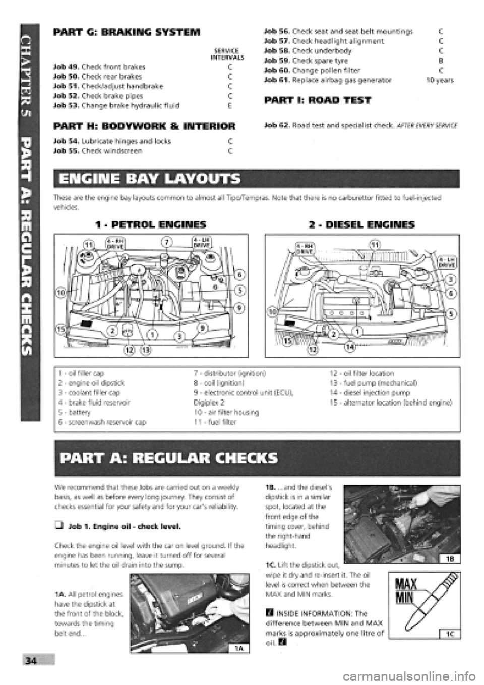
ENGINE BAY LAYOUTS
These are the engine bay layouts common to almost all Tipo/Tempras. Note that there is no carburettor fitted to fuel-injected
vehicles.
1 - PETROL ENGINES 2 - DIESEL ENGINES
1
-
oil filler cap 7
-
distributor (ignition) 12 - oil filter location
2
-
engine oil dipstick 8
-
coil (ignition) 13
-
fuel pump (mechanical)
3
-
coolant filler cap 9
-
electronic control unit (ECU), 14
-
diesel injection pump
4 - brake fluid reservoir Digiplex 2 15
-
alternator location (behind engine)
5 - battery 10
-
air filter housing
6
-
screenwash reservoir cap 11
-
fuel filter
PART A: REGULAR CHECKS
1B. ...and the diesel's
dipstick is in a similar
spot, located at the
front edge of the
timing cover, behind
the right-hand
headlight.
Q INSIDE INFORMATION: The
difference between MIN and MAX
marks is approximately one litre of
oil. Q
We recommend that these Jobs are carried out on a weekly
basis, as well as before every long journey. They consist of
checks essential for your safety and for your car's reliability.
• Job 1. Engine oil
-
check level.
Check the engine oil level with the car on level ground. If the
engine has been running, leave it turned off for several
minutes to let the oil drain into the sump.
1A. All petrol engines
have the dipstick at
the front of the block,
towards the timing
belt end...
1C. Lift the dipstick out,
wipe it dry and re-insert it. The oil
level is correct when between the
MAX and MIN marks.
Page 39 of 171
—I Job 13. Check cooling system.
SAFETY FIRST!
• The coolant level should be checked
-
and the
cooling system worked on, ONLY WHEN THE
COOLANT IS COLD. If you remove the pressure cap or
bleed screws when the engine is hot, scalding coolant
will spurt out.
• Keep anti-freeze away from children. If it is acciden-
tally swallowed or contacts skin or eyes, rinse
immediately with plenty of water and seek immediate
medical help.
Examine the cooling system hoses, looking for signs of
splitting, chafing and perishing. Squeeze the top and bottom
radiator hoses. Any hard, brittle areas or crackling sounds tell
you that the hoses are decomposing from the inside
-
replace-
ments needed!
SAFETY FIRST!
If
a
clearance is outside the tolerances shown in Chapter 3,
Facts
and Figures, the relevant shim will have to be changed.
New
shims
are available from your FIAT dealer. This work is
fully described in Chapter
6,
Repairs and Replacements.
10E. You must
always use a new
gasket, especially in
view of the oil level
mentioned earlier.
Clean the housing
and
cover faces and
use
the gasket dry.
11.
Examine the
belt
for wear. If
there
is
any
cracking, or if the
toothed side
10F.H INSIDE
INFORMATION:
The cover is 'anti-
crush'
-
you CAN'T
tighten beyond
the lugs pointed
out here
-
so
there's no point
trying! H
0 Job 11. Check camshaft timing belt.
Remove the camshaft belt outer cover. See Chapter 6,
Repairs
and Replacements, PART A: ENGINE.
FACT FILE: VALVE IDENTIFICATION:
T
—
Remember that clearances for inlet and
3™ exhaust valves differ. See
Chapter
3,
Facts and Figures. Counting from the
—^ timing belt end the valves are:
1.1,1.2 8-valve AND DIESEL ENGINES:
EXHAUST -1, 3, 6, 8. INLET
-
2, 4, 5, 7.
1372cc AND 1581cc ENGINES: EXHAUST -1, 4, 5, 8.
INLET
-
2, 3, 6, 7.
1.2 16-valve Hydraulic tappets
-
non-adjustable.
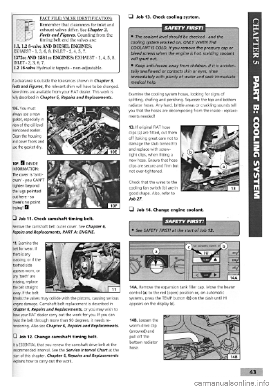
13. If original FIAT hose
clips (a) are fitted, cut them
off (taking great care not to
damage the stub beneath!)
and replace with screw-
tight clips, when fitting a
new hose. Ensure that hose
clips are secure and firm but
not over-tightened.
Check that the wires to the
cooling fan switch (b) are in
good shape. Also, refer to
Job
27
• Job 14. Change engine coolant.
• See SAFETY FIRST! at the start of Job 13.
appears worn, or
any 'teeth' are
missing, replace
the belt straight
away. If the belt
breaks
the valves may collide with the pistons, causing serious
engine damage. Camshaft belt replacement is described in
Chapter 6,
Repairs and Replacements, or you may wish to
have
your FIAT dealer carry out the work for you. If you can
twist the belt through more than 90 degrees, it needs re-
tensioning. Also see Chapter
6,
Repairs and Replacements.
m
AUtOKAlIC CtMAU s/
b
14A. Remove the expansion tank filler cap. Move the heater
control (a) to the red (open) position or, on automatic
systems, press the TEMP button (b) on the dash until HI
appears on the display (c).
—i Job 12. Change camshaft timing belt.
It is
ESSENTIAL that you renew the camshaft drive belt at the
recommended interval. See the Service Interval Chart at the
start
of this chapter. Chapter
6,
Repairs and Replacements
explains how to carry out the work.
14B. Loosen the
worm-drive clip
(arrowed) and
pull off the
bottom radiator
hose.
Page 40 of 171
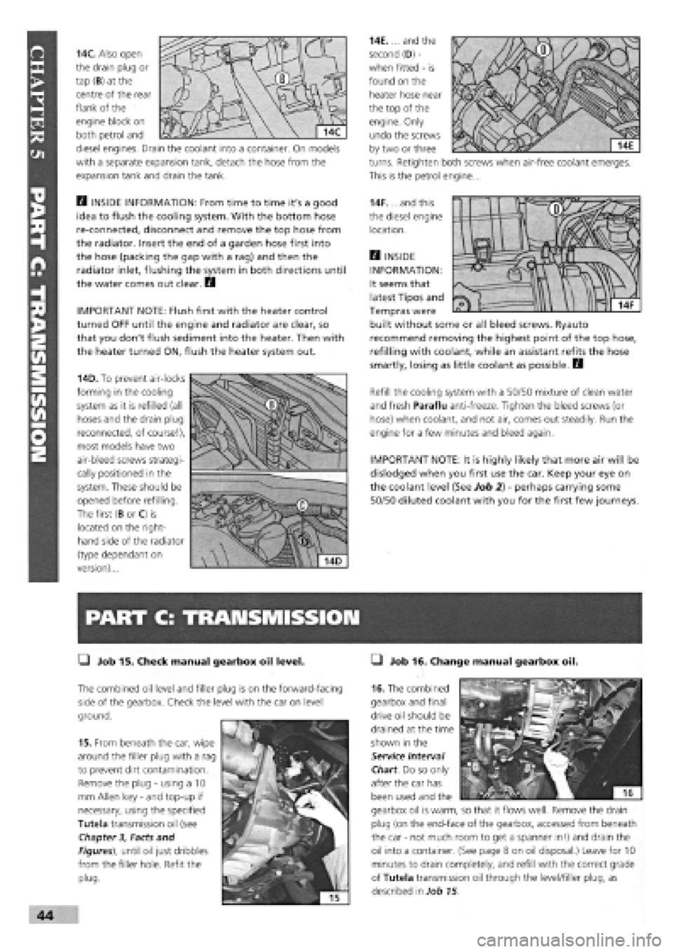
14C. Also open
the drain plug or
tap (B) at the
centre of the rear
flank of the
engine block on
both petrol and
diesel engines. Drain the coolant into a container. On models
with a separate expansion tank, detach the hose from the
expansion tank and drain the tank.
Q INSIDE INFORMATION: From time to time it's a good
idea to flush the cooling system. With the bottom hose
re-connected, disconnect and remove the top hose from
the radiator. Insert the end of a garden hose first into
the hose (packing the gap with a rag) and then the
radiator inlet, flushing the system in both directions until
the water comes out clear. Q
IMPORTANT NOTE: Flush first with the heater control
turned OFF until the engine and radiator are clear, so
that you don't flush sediment into the heater. Then with
the heater turned ON, flush the heater system out.
14D. To prevent air-locks
forming in the cooling
system as it is refilled (all
hoses and the drain plug
reconnected, of course!),
most models have two
air-bleed screws strategi-
cally positioned in the
system. These should be
opened before refilling.
The first (B or C) is
located on the right-
hand side of the radiator
(type dependant on
version)...
PART C: TRANSMISSION
• Job 15. Check manual gearbox oil level.
The combined oil level and filler plug is on the forward-facing
side of the gearbox. Check the level with the car on level
ground.
15. From beneath the car, wipe
around the filler plug with a rag
to prevent dirt contamination.
Remove the plug
-
using a 10
mm Allen key
-
and top-up if
necessary, using the specified
Tutela transmission oil (see
Chapter
3,
Facts and
Figures), until oil just dribbles
from the filler hole. Refit the
plug.
14E.... and the
second (D)
-
when fitted
-
is
found on the
heater hose near
the top of the
engine. Only
undo the screws
by two or three
turns. Retighten both screws when air-free coolant emerges.
This is the petrol engine...
14F. ...and this
the diesel engine
location.
H INSIDE
INFORMATION:
It seems that
latest Tipos and
Tempras were
built without some or all bleed screws. Ryauto
recommend removing the highest point of the top hose,
refilling with coolant, while an assistant refits the hose
smartly, losing as little coolant as possible. D
Refill the cooling system with a 50/50 mixture of clean water
and fresh Paraflu anti-freeze. Tighten the bleed screws (or
hose) when coolant, and not air, comes out steadily. Run the
engine for a few minutes and bleed again.
IMPORTANT NOTE: It is highly likely that more air will be
dislodged when you first use the car. Keep your eye on
the coolant level (See Job 2)
-
perhaps carrying some
50/50 diluted coolant with you for the first few journeys.
• Job 16. Change manual gearbox oil.
16. The combined
gearbox and final
drive oil should be
drained at the time
shown in the
Service Interval
Chart. Do so only
after the car has
been used and the
gearbox oil is warm, so that it flows well. Remove the drain
plug (on the end-face of the gearbox, accessed from beneath
the car
-
not much room to get a spanner in!) and drain the
oil into a container. (See page 8 on oil disposal.) Leave for 10
minutes to drain completely, and refill with the correct grade
of Tutela transmission oil through the level/filler plug, as
described in Job 15.
Page 50 of 171
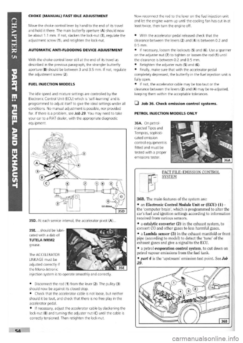
CHOKE (MANUAL) FAST IDLE ADJUSTMENT
Move the choke control lever by hand to the end of its travel
and hold it there. The main butterfly aperture (A) should now
be about 1.1 mm. If not, slacken the lock-nut (3), regulate the
adjustment screw (1), and retighten the lock-nut.
AUTOMATIC ANTI-FLOODING DEVICE ADJUSTMENT
With the choke control lever still at the end of its travel as
described in the previous paragraph, the strangler butterfly
aperture (B) should be between 3 and 3.5 mm. If not, regulate
the adjustment screw (2).
FUEL INJECTION MODELS
The idle speed and mixture settings are controlled by the
Electronic Control Unit (ECU) which is 'self-learning' and is
programmed to adjust itself to give the ideal settings under all
conditions. No manual adjustment is possible, nor provided
for. If there is a problem, see Job 29 You may need to take
your car to a FIAT dealer, with the appropriate diagnostic
equipment.
35D. At each service interval, the accelerator pivot (A).
35E. ...should be lubri-
cated with a dab of
TUTELA MRM2
grease.
The ACCELERATOR
LINKAGE must be
adjusted correctly if
the Mono-Jetronic
injection system is to operate smoothly and correctly.
• Disconnect the rod (1) from the lever (2). The pulley (3)
should now be against its closed stop.
• Check that the accelerator cable is not loose, but neither
should it be taut, and check that there is no free play in the
accelerator pedal.
• If necessary, adjust the accelerator cable by slackening the
lock-nut (B) and turning the adjuster nut (C) until the cable is
correctly tensioned. Then retighten the lock-nut.
Now reconnect the rod to the lever on the fuel injection unit
and let the engine warm up until the cooling fan has cut in at
least twice, then turn the engine off.
• With the accelerator pedal released check that the
clearance between the levers (2) and (4) is between 0.2 and
0.5 mm.
• If necessary, loosen the lockouts (5) and (6). Use a spanner
on the adjuster nut (7) to tighten or loosen the rod (1) until
the clearance is between 0.2 and 0.5 mm.
• Retighten the adjuster nuts (5) and (6).
• Finally, make sure that with the accelerator pedal
completely depressed, the butterfly in the fuel injection unit is
fully open.
• If not, the accelerator cable may be too taut or the
clearance between the levers (2) and (4) may be re-adjusted,
keeping them within the acceptable tolerances.
Q Job 36. Check emission control systems.
PETROL INJECTION MODELS ONLY
36A. On petrol-
injected Tipos and
Tempras, sophisti-
cated emission
control equipment is
fitted and must be
tested with a proper
emissions tester.
FACT FILE: EMISSION CONTROL
SYSTEM
36B. The main features of the system are:
• an Electronic Control Module Unit or (ECU) (1) -
the 'computer brain', which is programmed to alter the
car's fuel and ignition settings according to information
received from various sensors.
• a catalytic converter (2) in the exhaust system, to
convert CO and other gases to less harmful gases.
• a Lambda sensor (3) in the exhaust manifold or front
pipe (according to model) to detect the 'tune' of the
exhaust gases and give a signal to the ECU.
• a petrol evaporation control system, to cut down on
petrol vapour emissions from the fuel tank.
• part 4 is the 'upstream' emission test point. See Job
29.
Page 51 of 171
ELECTRONIC CONTROL MODULE: The ECU is not an item
that requires any servicing. If you think it might be faulty, ask
your FIAT dealer or fuel injection specialist to check it for you.
This must be done by someone with the correct FIAT plug-in
diagnostic equipment and data.
CATALYTIC CONVERTER: The CAT is not serviceable. If it
fails, you will be told at the MoT test. Replacement is
expensive, so we recommend you obtain a second opinion
before replacing the 'cat'.
LAMBDA SENSOR: For information concerning the sensor,
see
Job
37.
I' sensor is a simple job (see
Chapter 6, Repairs and
Replacements, PART F: FUEL AND EXHAUST), but it
can only be tested by your FIAT dealer with the correct
equipment
• If the sensor is faulty, have it renewed by your
dealer.
• Lambda sensors are very delicate and easily
damaged. It is not likely that you would be able to
return one to the supplier if you fitted it yourself.
• Lambda sensors are only fitted to cars with a
catalytic converter.
• Job 38. Check/adjust diesel idle speed.
To accurately check and adjust the diesel's idle speed you
need a diesel-specific rev-counter. If you're happy with the idle
speed, leave well alone. But if you're convinced the idle is
incorrect, it's best to take the car to a FIAT dealer. If you wish
to adjust the speed yourself, get the engine to normal
operating temperature, and check there is some free play in
the accelerator cable before proceeding.
ADJUSTMENT
-
BOSCH PUMP
D INSIDE INFORMATION: If the canister is flooded with
petrol, it is probable that one of the purge valves or
purge valve floats is faulty. Get this investigated and
rectified by a FIAT dealer. If the engine cuts out and then
restarts after a while, it could be the breather hose
valve, fitted under the fuel filler neck. This one-way
valve allows air to enter the tank as the fuel level falls,
otherwise an air lock can prevent fuel reaching the
engine. To test the valve, take off the pipe clips, remove
the valve and test it as for the canister one-way valve,
above. It should allow air to pass into the tank, but not
the other way. H
Q Job 37. Check Lambda sensor.
PETROL INJECTION MODELS ONLY
For
a
description of how the sensor works, see Job 36, FACT
FILE: EMISSION CONTROL SYSTEM. It should be checked at
the recommended interval
-
the cost of checking and
replacing the sensor is far less than that of having to replace
the catalytic converter because it has been polluted due to a
sensor fault.
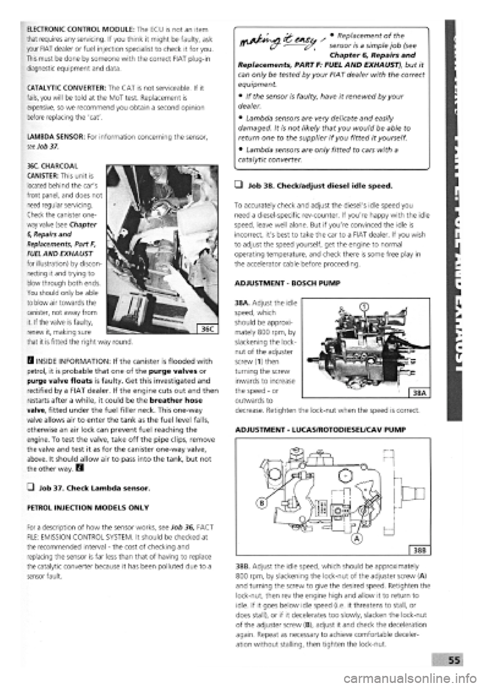
38A. Adjust the idle
speed, which
should be approxi-
mately 800 rpm, by
slackening the lock-
nut of the adjuster
screw (1) then
turning the screw
inwards to increase
the speed
-
or
outwards to
decrease. Retighten the lock-nut when the speed is correct.
ADJUSTMENT
-
LUCAS/ROTODIESEL/CAV PUMP
38B. Adjust the idle speed, which should be approximately
800 rpm, by slackening the lock-nut of the adjuster screw (A)
and turning the screw to give the desired speed. Retighten the
lock-nut, then rev the engine high and allow it to return to
idle. If it goes below idle speed (i.e. it threatens to stall, or
does stall), or if it decelerates too slowly, slacken the lock-nut
of the adjuster screw (B), adjust it and check the deceleration
again. Repeat as necessary to achieve comfortable deceler-
ation without stalling, then tighten the lock-nut.
36C. CHARCOAL
CANISTER: This unit is
located behind the car's
front panel, and does not
need regular servicing.
Check the canister one-
way valve (see Chapter
6,
Repairs and
Replacements, Part F,
FUEL
AND EXHAUST
for illustration) by discon-
necting it and trying to
blow through both ends.
You should only be able
to blow air towards the
canister, not away from
it. If the valve is faulty,
renew it, making sure
that it
is
fitted the right way round.
Page 59 of 171
—1 Job 59. Check spare tyre.
This
job should ideally be carried out every month or two
-
you
never know when you're going to need that spare! But if you
haven't remembered, do it at the time shown on the Service
Interval Chart at the latest.
Q INSIDE INFORMATION: Put in the maximum recom-
mended pressure for heavy-duty use
-
it's always easier
to let some air out if necessary, than to put some in. Lift
the spare out check the 'hidden' lower side wall
for cracking. See Job 6. E9
PART I: ROAD TEST
Q Job 62. Road test and specialist check
-
after
every service.
Before you can claim to have 'finished' working on your car,
you must check it, test it, and, if necessary, have a qualified
mechanic check it over for you.
If you
are not a qualified mechanic, we strongly recommend
having someone who is a properly qualified mechanic
-
your
FIAT dealership perhaps
-
inspect all of the car's safety-related
items
after they have been worked on at home and before
using
the car on the road.
You'll have to remove the toolkit and the wheel to get at the
valve
-
under the boot floor on most models but to one side of
the rear compartment on Estate versions.
• Job 60. Change pollen filter.
When fitted to the fresh air intake, replace it at the scheduled
mileage interval.
• Job 61. Replace airbag gas generator.
Have your FIAT dealer replace the airbag gas generator 10
years after the car was built
-
see the label inside the car's
glove compartment door.
• Before setting out, check that the lights, indicators and in-
car controls, as well as seat belts and seat adjustments, all
work correctly.
• Run the car for several minutes before setting out then turn
off, check fluid levels and check underneath for leaks.
• Check that the steering moves freely in both directions and
that the car does not 'pull' one way or the other when driving
in a straight line
-
but do bear in mind the effect of the
camber on the road.
• Make sure that the brakes work effectively, smoothly and
without the need for 'pumping'. There should be no juddering
or squealing.
• Check that the car does not 'pull' from one side to the
other when you brake firmly from around 40 mph. (Don't
cause a skid and don't try this if there is any following traffic.)
"V,
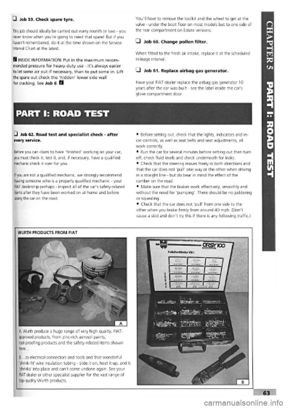
WURTH PRODUCTS FROM FIAT
A.
Wurth produce a huge range of very high quality, FIAT-
approved products, from zinc-rich aerosol paints,
rust-proofing products and the safety-related items shown
here...
B. ...to electrical connectors and tools and that wonderful
'shrink-fit' wire insulation tubing
-
slide it on, heat it up, and it
'shrinks' into place and can't come undone again. See your
FIAT dealer or other specialist supplier for the vast range of
top-quality Wurth products.
Page 150 of 171
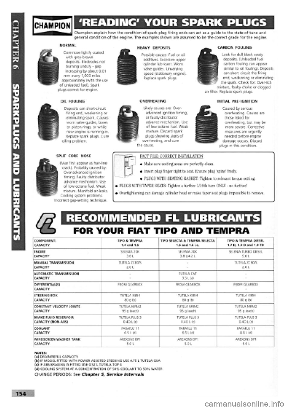
gjpjgjjl 'READING' YOUR SPARK PLUGS
Champion explain how the condition of spark plug firing ends can act as a guide to the state of tune and general condition of the engine. The examples shown are assumed to be the correct grade for the engine.
NORMAL
Core nose lightly coated with grey-brown deposits. Electrodes not burning unduly
-
gap increasing by about 0.01 mm every 1,000 miles approximately (with the use of unleaded fuel). Spark plugs correct for engine.
OIL FOULING
Deposits can short-circuit firing end, weakening or eliminating spark. Causes: worn valve guides, bores or piston rings, or while new engine is running-in. Replace spark plugs. Cure oiling problem.
SPLIT CORE NOSE
(May first appear as hair-line-crack). Probably caused by: Over-advanced ignition timing. Faulty distributor advance mechanism. Use of low octane fuel. Weak mixture. Manifold air-leaks. Cooling system problems. Incorrect gap-setting technique.
HEAVY DEPOSITS
Possible causes: Fuel or oil additives. Excessive upper cylinder lubricant. Worn valve guides. Unvarying speed (stationary engine). Replace spark plugs.
OVERHEATING
Likely causes are: Over-advanced ignition timing, or faulty distributor advance mechanism. Use of low octane fuel. Weak mixture. Discard spark plugs showing signs of overheating, and cure the cause.
CARBON FOULING
Look for dull black sooty deposits. (Unleaded fuel carbon fouling can appear similar to oil fouling). Deposits can short circuit the firing end, weakening or eliminating the spark. Check for: Over-rich mixture, faulty choke or clogged air filter. Replace spark plugs.
INITIAL PRE-IGNITION
Caused by serious overheating. Causes are those listed for overheating, but may be more severe. Corrective measures are urgently needed before engine damage occurs. Discard plugs in this condition.
FACT FILE: CORRECT INSTALLATION
• Make sure seating areas are perfectly clean.
• Insert plug finger tight to seat. Ensure plug 'spins' freely.
• PLUGS WITH SEATING GASKET: Tighten to relevant torque setting.
• PLUGS WITH TAPER SEATS: Tighten a further l/16th turn ONLY - no further!
• Overtightening can damage cylinder head or make taper seat plugs impossible to remove.
RECOMMENDED FL LUBRICANTS
FOR YOUR FIAT TIPO ARID TEMPRA
COMPONENT/ TIPO & TEMPRA TIPO SELECTA & TEMPRA SELECTA TIPO & TEMPRA DIESEL CAPACITY 1.4 and 1.6 1.6 and 1.6 i.e. 1.7 D, 1.9 Dand 1.9 TD
ENGINE SELENIA 20K SELENIA 20K SELENIA TURBO DIESEL CAPACITY 3.8 L 3.8 L/4.2 L 5.0 L
MANUAL TRANSMISSION TUTELA ZC80/S -TUTELA ZC80/S CAPACITY 2.0 L -2.0 L
AUTOMATIC TRANSMISSION -TUTELA CVT -CAPACITY -3.5 L (a) -
DIFFERENTIAL(S) FROM GEARBOX FROM GEARBOX FROM GEARBOX CAPACITY ---
STEERING BOX TUTELA K854 TUTELA K854 TUTELA K854 CAPACITY 80 g (b) 80 g (b) 80 g (b)
CONSTANT VELOCITY JOINTS TUTELA MRM2 TUTELA MRM2 TUTELA MRM2 CAPACITY 95 g (each) 95 g (each) 95 g (each)
BRAKE FLUID RESERVOIR TUTELA PLUS 3 TUTELA PLUS 3 TUTELA PLUS 3 CAPACITY (NON-ABS) 0.40
L
(c) 0.40 L (c) 0.40
L
(c)
COOLANT PARAFLU 11 PARAFLU 11 PARAFLU 11 CAPACITY 6.5 L(d) 6.5 L(d) 8.8
L
(d)
WINDSCREEN WASHER TANK AREXONS DP1 AREXONS DP1 AREXONS DP1 CAPACITY 5.0 L 5.0 L 5.0 L
NOTES: (a) DRAIN/REFILL CAPACITY (b) IF MODEL FITTED WITH POWER ASSISTED STEERING USE 0.75 L TUTELA Gl/A (c) IF ABS BRAKING IS FITTED USE 0.52 L TUTELA TOP 4 (d) COOLING SYSTEM AT A CONCENTRATION OF 50% COOLANT TO 50% WATER
CHANGE PERIODS: See Chapter 5, Service Intervals
154