sensor FIAT TIPO 5DOORS STATION WAGON 2018 Owner handbook (in English)
[x] Cancel search | Manufacturer: FIAT, Model Year: 2018, Model line: TIPO 5DOORS STATION WAGON, Model: FIAT TIPO 5DOORS STATION WAGON 2018Pages: 292, PDF Size: 7.74 MB
Page 125 of 292
Deactivation
With the device active, to deactivate it
press and release the button
. The
display will show a dedicated message.
SETTING THE DESIRED
SPEED
The device can only be set with the
speed over 30 km/h (or equivalent
in mph) and under 160 km/h (or
equivalent in mph). When the car
reaches the desired speed, press and
release the button SET + or SET – the
display will show the set speed.
With the system set, the relative symbol
(fig. 124 ) is white.
Then take your foot off the accelerator
pedal.
IMPORTANT Pressing the accelerator
pedal again, the car’s speed may
exceed the set value.
While the accelerator pedal is pressed:
a dedicated message is displayed for
a few seconds;
the device will not be able to control
the distance between the vehicle and
the one ahead. In this case the speed
will be determined only by the position
of the accelerator pedal.
The device will return to normal
operation as soon as the accelerator
pedal is released.The systemcannotbe set:
when pressing the brake pedal;
when the manual parking brake has
been operated;
when the brakes are overheated;
when the shift lever is in the R
(reverse), neutral or in 1st(first gear
engaged) positions (versions with
manual transmission);
when the shift lever is in the P (park),
R (reverse) or N (neutral) positions
(versions with automatic transmission or
dual-clutch automatic transmission);
when the clutch is pressed;
when the car speed is not within the
settable speed range;
when the engine speed exceeds a
maximum threshold (versions with
manual transmission and versions with
automatic transmission/dual-clutch
automatic transmission) or goes below
a minimum threshold (only versions with
manual transmission);
when the ESC (or ABS or other
stability control systems) are operating
or have just operated;
during automatic braking by the Full
Brake Control system;
when the Speed Limiter is active;
when the electronic Cruise Control is
active;
in case of failure of the device;
when the engine is off;
in case of obstruction of the radar
sensor (in this case the bumper area
where it is located must be cleaned).
In case of system set, the conditions
described above also cause a
cancellation or deactivation of the
system with times that may vary
according to the conditions.
IMPORTANT With the device set, it is
possible to reach speeds higher than
those set in the system by pressing the
accelerator pedal. In this situation, the
device does not turn off automatically,
but the device’s functions are limited: it
is therefore recommended to turn it off.
CHANGING THE SPEED
Speed increase
After having set the device, the stored
speed can be stored by holding the
SET + button pressed.
Press the SET + button once, the set
speed will increase by 1 km/h (or the
equivalent in mph). Each subsequent
touch of the button will increase the
speed by 1 km/h (or the equivalent
in mph).
Hold the SET + button down, the set
speed will increase in 10 km/h steps (or
the equivalent in mph) until the button is
released. The set speed increase is
shown on the display.
123
Page 127 of 292
RECALLING THE SPEED
Once the system has been cancelled
but not deactivated, if a speed was
previously set simply press the RES
(Resume) button and remove your foot
from the accelerator to recall it.
The system will be set to the last stored
speed.
Before returning to the previously set
speed, bring the speed close to that
value, press the RES (Resume) button
and then release it.
IMPORTANT The recall function must
only be used if the road and traffic
conditions so allow. Recalling an
excessively high or low speed for the
current traffic and road conditions could
cause an acceleration or a deceleration
of the vehicle. Failure to comply with
these precautions may cause serious
accidents and fatal injuries.
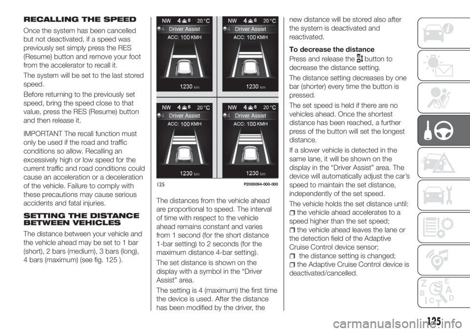
SETTING THE DISTANCE
BETWEEN VEHICLES
The distance between your vehicle and
the vehicle ahead may be set to 1 bar
(short), 2 bars (medium), 3 bars (long),
4 bars (maximum) (see fig. 125 ).The distances from the vehicle ahead
are proportional to speed. The interval
of time with respect to the vehicle
ahead remains constant and varies
from 1 second (for the short distance
1-bar setting) to 2 seconds (for the
maximum distance 4-bar setting).
The set distance is shown on the
display with a symbol in the “Driver
Assist” area.
The setting is 4 (maximum) the first time
the device is used. After the distance
has been modified by the driver, thenew distance will be stored also after
the system is deactivated and
reactivated.
To decrease the distance
Press and release the
button to
decrease the distance setting.
The distance setting decreases by one
bar (shorter) every time the button is
pressed.
The set speed is held if there are no
vehicles ahead. Once the shortest
distance has been reached, a further
press of the button will set the longest
distance.
If a slower vehicle is detected in the
same lane, it will be shown on the
display in the “Driver Assist” area. The
device will automatically adjust the car’s
speed to maintain the set distance,
independently of the set speed.
The vehicle holds the set distance until:
the vehicle ahead accelerates to a
speed higher than the set speed;
the vehicle ahead leaves the lane or
the detection field of the Adaptive
Cruise Control device sensor;
the distance setting is changed;
the Adaptive Cruise Control device is
deactivated/cancelled.
125P2000094-000-000
125
Page 128 of 292
IMPORTANT The maximum breaking
applied by the device is limited. The
driver may apply the brakes in all cases
if needed.
IMPORTANT If the device predicts that
the braking level is not sufficient to hold
the set distance, the driver is warned by
a message indicating that the vehicle
ahead is too close. An acoustic signal is
also emitted. In this case, it is advisable
to brake immediately as necessary to
hold a safe distance from the vehicle
ahead.
IMPORTANT The driver is responsible
for ensuring that there are no
pedestrians, other vehicles or
objectives along the direction of the
vehicle. Failure to comply with these
precautions may cause serious
accidents and injuries.
IMPORTANT The driver is fully
responsible for holding a safe distance
from the vehicle ahead respecting the
highway code in force in the respective
country.
DEACTIVATION
The device is deactivated and the set
speed is cancelled if:
thebutton is pressed on the
Adaptive Cruise Control;
thebutton is pressed on the
electronic Cruise Control;
the Speed Limiter button is pressed;
the ignition device is in the STOP
position.
The device is cancelled (the set speed
and distance are stored):
when the CANC button is pressed;
when the conditions shown in the
“Setting the desired speed” paragraph
occur;
when the vehicle speed drops under
the minimum set speed (e.g. in
presence of slow vehicles).
If these conditions occur while the
system is decelerating with respect to a
vehicle ahead, the system could
continue the deceleration, if necessary,
also after it is cancelled or deactivated
within the minimum speed settable on
the system.
SYSTEM LIMITED
OPERATION WARNING
If the dedicated message is shown on
the display, a condition limiting the
system operation may have occurred.
This limitation could be caused by a
fault or obstruction of the radar sensor.
If an obstruction is signalled, clean the
area of the bumper in which the sensor
is located in fig. 122 and check that the
message has disappeared.When the conditions limiting the system
functions end, this will go back to
normal and complete operation. Should
the fault persist, contact a Fiat
Dealership.
PRECAUTIONS WHILE
DRIVING
The device may not work correctly in
some driving conditions (see below):
the driver must control the vehicle at all
times.
Towing a trailer
Use of the device is not recommended
while towing a trailer.
Vehicle not aligned
The device may not detect a vehicle
travelling on the same lane but which is
not aligned along the same direction of
travel or a vehicle which is cutting in
from a side lane. Sufficient distance
from the vehicles ahead may not be
guaranteed in these cases.
The non-aligned vehicle can weave in
and out of the driving direction causing
the vehicle to brake or accelerate
unexpectedly.
Steering and curves
On curves fig. 126 with the device set,
it could limit speed and acceleration to
guarantee vehicle stability even if no
vehicles are detected ahead.
126
STARTING AND DRIVING
Page 130 of 292
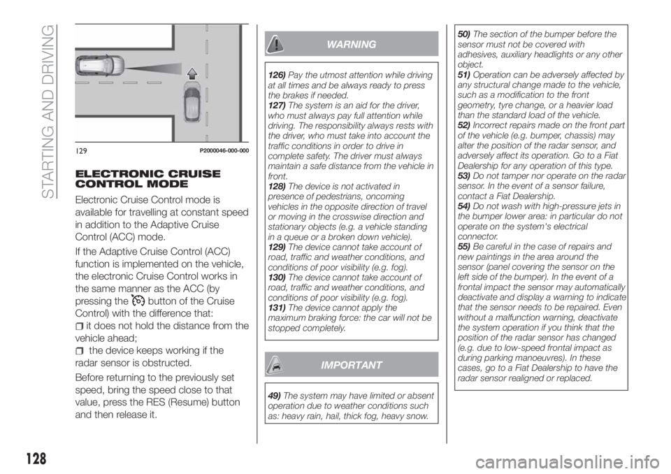
ELECTRONIC CRUISE
CONTROL MODE
Electronic Cruise Control mode is
available for travelling at constant speed
in addition to the Adaptive Cruise
Control (ACC) mode.
If the Adaptive Cruise Control (ACC)
function is implemented on the vehicle,
the electronic Cruise Control works in
the same manner as the ACC (by
pressing the
button of the Cruise
Control) with the difference that:
it does not hold the distance from the
vehicle ahead;
the device keeps working if the
radar sensor is obstructed.
Before returning to the previously set
speed, bring the speed close to that
value, press the RES (Resume) button
and then release it.
WARNING
126)Pay the utmost attention while driving
at all times and be always ready to press
the brakes if needed.
127)The system is an aid for the driver,
who must always pay full attention while
driving. The responsibility always rests with
the driver, who must take into account the
traffic conditions in order to drive in
complete safety. The driver must always
maintain a safe distance from the vehicle in
front.
128)The device is not activated in
presence of pedestrians, oncoming
vehicles in the opposite direction of travel
or moving in the crosswise direction and
stationary objects (e.g. a vehicle standing
in a queue or a broken down vehicle).
129)The device cannot take account of
road, traffic and weather conditions, and
conditions of poor visibility (e.g. fog).
130)The device cannot take account of
road, traffic and weather conditions, and
conditions of poor visibility (e.g. fog).
131)The device cannot apply the
maximum braking force: the car will not be
stopped completely.
IMPORTANT
49)The system may have limited or absent
operation due to weather conditions such
as: heavy rain, hail, thick fog, heavy snow.50)The section of the bumper before the
sensor must not be covered with
adhesives, auxiliary headlights or any other
object.
51)Operation can be adversely affected by
any structural change made to the vehicle,
such as a modification to the front
geometry, tyre change, or a heavier load
than the standard load of the vehicle.
52)Incorrect repairs made on the front part
of the vehicle (e.g. bumper, chassis) may
alter the position of the radar sensor, and
adversely affect its operation. Go to a Fiat
Dealership for any operation of this type.
53)Do not tamper nor operate on the radar
sensor. In the event of a sensor failure,
contact a Fiat Dealership.
54)Do not wash with high-pressure jets in
the bumper lower area: in particular do not
operate on the system's electrical
connector.
55)Be careful in the case of repairs and
new paintings in the area around the
sensor (panel covering the sensor on the
left side of the bumper). In the event of a
frontal impact the sensor may automatically
deactivate and display a warning to indicate
that the sensor needs to be repaired. Even
without a malfunction warning, deactivate
the system operation if you think that the
position of the radar sensor has changed
(e.g. due to low-speed frontal impact as
during parking manoeuvres). In these
cases, go to a Fiat Dealership to have the
radar sensor realigned or replaced.
129P2000046-000-000
128
STARTING AND DRIVING
Page 131 of 292

PARKING SENSORS
(where provided)
SENSORS
132)
56) 57) 58)
The parking sensors, located in the rear
bumper fig. 130, are used to detect the
presence of any obstacles near the rear
part of the vehicle.
The sensors warn the driver about the
presence of possible obstacles with an
intermittent acoustic signal and,
depending on the version, also with
visual indications on the instrument
panel display.
Activation
The sensors are automatically activated
when reverse gear is selected.As the distance from the obstacle
behind the vehicle decreases, the
frequency of the acoustic signal
increases.
Acoustic signal
When reverse is engaged and there is
an obstacle behind the vehicle, an
acoustic signal is activated and the
signal varies as the distance of the
obstacle from the bumper varies.
The frequency of the acoustic signal:
increases as the distance between
the vehicle and the obstacle decreases;
becomes continuous when the
distance separating the vehicle from the
obstacle is less than about 30 cm;
is constant if the distance between
the vehicle and the obstacle is
unchanged. If this situation concerns
the side sensors, the signal will stop
after approximately 3 seconds to avoid,
for example, indications in the event of
manoeuvres along a wall.
stops immediately if the distance of
the obstacle increases.
When the system emits the acoustic
signal, the volume of theUconnect™
system (where provided) is
automatically lowered.Detection distances
If several obstacles are detected by the
sensors, only the nearest one is
considered.
Indication on display
The indications regarding the Park
Assist system are shown only if the
"Acoustic signal and display" item in the
"Settings" menu of theUconnect™ 5"
or7" HDsystem (where provided) was
previously selected (for more
information, see the description in the
dedicated chapter).
The system indicates the presence of
an obstacle by displaying a single arc in
one of the possible areas, in
accordance with the distance of the
object and the position in relation to the
vehicle. If the obstacle is detected in the
rear central area, a single arc will be
displayed as the obstacle approaches,
first constant, then flashing, in addition
to an acoustic signal.FAULT INDICATION
Parking sensor faults, if any, will be
indicated when reverse is engaged by
the switching on of the
symbol on
the instrument panel together with the
message on the display (see
description in the "Warning lights and
messages" paragraph, "Knowing the
instrument panel" chapter).
130P2000007-000-000
129
Page 132 of 292
OPERATION WITH A
TRAILER
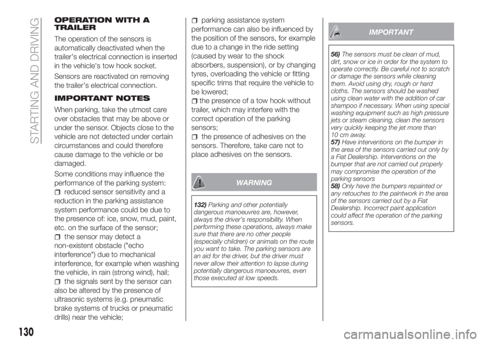
The operation of the sensors is
automatically deactivated when the
trailer's electrical connection is inserted
in the vehicle's tow hook socket.
Sensors are reactivated on removing
the trailer's electrical connection.
IMPORTANT NOTES
When parking, take the utmost care
over obstacles that may be above or
under the sensor. Objects close to the
vehicle are not detected under certain
circumstances and could therefore
cause damage to the vehicle or be
damaged.
Some conditions may influence the
performance of the parking system:
reduced sensor sensitivity and a
reduction in the parking assistance
system performance could be due to
the presence of: ice, snow, mud, paint,
etc. on the surface of the sensor;
the sensor may detect a
non-existent obstacle ("echo
interference") due to mechanical
interference, for example when washing
the vehicle, in rain (strong wind), hail;
the signals sent by the sensor can
also be altered by the presence of
ultrasonic systems (e.g. pneumatic
brake systems of trucks or pneumatic
drills) near the vehicle;
parking assistance system
performance can also be influenced by
the position of the sensors, for example
due to a change in the ride setting
(caused by wear to the shock
absorbers, suspension), or by changing
tyres, overloading the vehicle or fitting
specific trims that require the vehicle to
be lowered;
the presence of a tow hook without
trailer, which may interfere with the
correct operation of the parking
sensors;
the presence of adhesives on the
sensors. Therefore, take care not to
place adhesives on the sensors.
WARNING
132)Parking and other potentially
dangerous manoeuvres are, however,
always the driver’s responsibility. When
performing these operations, always make
sure that there are no other people
(especially children) or animals on the route
you want to take. The parking sensors are
an aid for the driver, but the driver must
never allow their attention to lapse during
potentially dangerous manoeuvres, even
those executed at low speeds.
IMPORTANT
56)The sensors must be clean of mud,
dirt, snow or ice in order for the system to
operate correctly. Be careful not to scratch
or damage the sensors while cleaning
them. Avoid using dry, rough or hard
cloths. The sensors should be washed
using clean water with the addition of car
shampoo if necessary. When using special
washing equipment such as high pressure
jets or steam cleaning, clean the sensors
very quickly keeping the jet more than
10 cm away.
57)Have interventions on the bumper in
the area of the sensors carried out only by
a Fiat Dealership. Interventions on the
bumper that are not carried out properly
may compromise the operation of the
parking sensors
58)Only have the bumpers repainted or
any retouches to the paintwork in the area
of the sensors carried out by a Fiat
Dealership. Incorrect paint application
could affect the operation of the parking
sensors.
130
STARTING AND DRIVING
Page 135 of 292

IMPORTANT NOTES
IMPORTANT In some circumstances,
such as with ice, snow or mud on the
surface of the camera, the camera
sensitivity may be reduced.
IMPORTANT When parking, take the
utmost care over obstacles that may be
above or under the camera range.
WARNING
133)Parking and other potentially
dangerous manoeuvres are, however,
always the driver’s responsibility. While
carrying out these manoeuvres, always
make sure that no people (especially
children) or animals are in the area
concerned. The camera is an aid for the
driver, but the driver must never allow
his/her attention to lapse during potentially
dangerous manoeuvres, even those
executed at low speeds. Always keep a
slow speed, so as to promptly brake in the
case of obstacles.
IMPORTANT
59)It is vital, for correct operation, that the
camera is always kept clean and free from
any mud, dirt, snow or ice. Be careful not
to scratch or damage the camera while
cleaning it. Avoid using dry, rough or hard
cloths. The camera must be washed using
clean water, with the addition of car
shampoo if necessary. In washing stations
which use steam or high-pressure jets,
clean the camera quickly, keeping the
nozzle more than 10 cm away from the
sensors. Also, do not apply stickers to the
camera.
TOWING TRAILERS
IMPORTANT NOTES
134) 135)
For towing caravans or trailers the
vehicle must be fitted with an approved
tow hook and an adequate electrical
system. Should aftermarket installation
be requested, this must be carried out
by specialists.
Install any specific and/or additional
door mirrors as specified by the
Highway Code.
Remember that, when towing a trailer,
steep hills are harder to climb, braking
distances increase and overtaking takes
longer depending on the overall weight
of the trailer.
Engage a low gear when driving
downhill, rather than constantly using
the brake.
The weight the trailer exerts on the
vehicle tow hook reduces the vehicle's
loading capacity by the same amount.
To make sure that the maximum
towable weight is not exceeded (given
in the vehicle registration document)
account should be taken of the fully
laden trailer, including accessories and
luggage.
133
Page 176 of 292
Thousands of miles9 182736455463728190
Thousands of kilometres15 30 45 60 75 90 105 120 135 150
Years12345678910
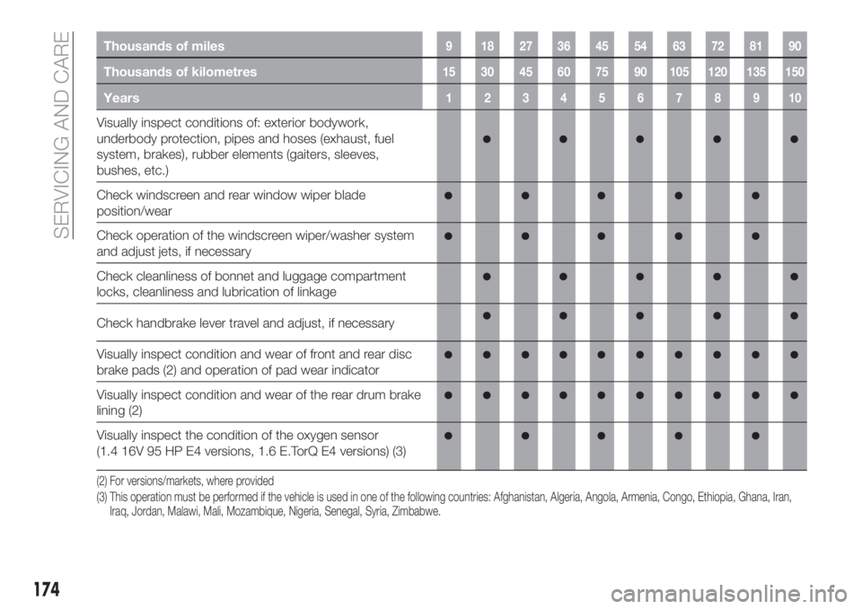
Visually inspect conditions of: exterior bodywork,
underbody protection, pipes and hoses (exhaust, fuel
system, brakes), rubber elements (gaiters, sleeves,
bushes, etc.)
Check windscreen and rear window wiper blade
position/wear
Check operation of the windscreen wiper/washer system
and adjust jets, if necessary
Check cleanliness of bonnet and luggage compartment
locks, cleanliness and lubrication of linkage
Check handbrake lever travel and adjust, if necessary
Visually inspect condition and wear of front and rear disc
brake pads (2)
and operation of pad wear indicator
Visually inspect condition and wear of the rear drum brake
lining (2)
Visually inspect the condition of the oxygen sensor
(1.4 16V 95 HP E4 versions, 1.6 E.TorQ E4 versions) (3)
(2) For versions/markets, where provided
(3) This operation must be performed if the vehicle is used in one of the following countries: Afghanistan, Algeria, Angola, Armenia, Congo, Ethiopia, Ghana, Iran,
Iraq, Jordan, Malawi, Mali, Mozambique, Nigeria, Senegal, Syria, Zimbabwe.
174
SERVICING AND CARE
Page 179 of 292
Thousands of miles9 182736455463728190
Thousands of kilometres15 30 45 60 75 90 105 120 135 150
Years12345678910
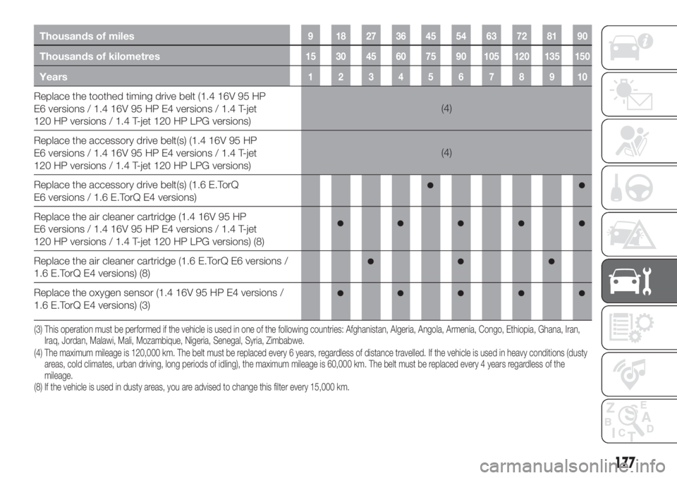
Replace the toothed timing drive belt (1.4 16V 95 HP
E6 versions / 1.4 16V 95 HP E4 versions / 1.4 T-jet
120 HP versions / 1.4 T-jet 120 HP LPG versions)(4)
Replace the accessory drive belt(s) (1.4 16V 95 HP
E6 versions / 1.4 16V 95 HP E4 versions / 1.4 T-jet
120 HP versions / 1.4 T-jet 120 HP LPG versions)(4)
Replace the accessory drive belt(s) (1.6 E.TorQ
E6 versions / 1.6 E.TorQ E4 versions)
Replace the air cleaner cartridge (1.4 16V 95 HP
E6 versions / 1.4 16V 95 HP E4 versions / 1.4 T-jet
120 HP versions / 1.4 T-jet 120 HP LPG versions) (8)
Replace the air cleaner cartridge (1.6 E.TorQ E6 versions /
1.6 E.TorQ E4 versions) (8)
Replace the oxygen sensor (1.4 16V 95 HP E4 versions /
1.6 E.TorQ E4 versions) (3)
177
(4) The maximum mileage is 120,000 km. The belt must be replaced every 6 years, regardless of distance travelled. If the vehicle is used in heavy conditions (dusty
areas, cold climates, urban driving, long periods of idling), the maximum mileage is 60,000 km. The belt must be replaced every 4 years regardless of the
mileage.
(8) If the vehicle is used in dusty areas, you are advised to change this filter every 15,000 km. (3) This operation must be performed if the vehicle is used in one of the following countries: Afghanistan, Algeria, Angola, Armenia, Congo, Ethiopia, Ghana, Iran,
Iraq, Jordan, Malawi, Mali, Mozambique, Nigeria, Senegal, Syria, Zimbabwe.
Page 197 of 292
BATTERY
RECHARGING
IMPORTANT NOTES
IMPORTANT The battery recharging
procedure is given as information only.
To carry out this operation contact a
Fiat Dealership.
IMPORTANT After setting the ignition
device to STOP and having closed the
driver side door, wait at least one
minute before disconnecting the
electrical supply from the battery. When
reconnecting the electrical supply to the
battery, make sure that the ignition
device is in the STOP position and the
driver side door is closed.
IMPORTANT Charging should be slow
at a low ampere rating for
approximately 24 hours. Charging for a
longer time may damage the battery.
IMPORTANT The cables of the
electrical system must be correctly
reconnected to the battery, i.e. the
positive cable (+) to the positive
terminal and the negative cable (–) to
the negative terminal. The battery
terminals are marked with the positive
(+) and negative (–) symbols, and are
shown on the battery cover. The battery
terminals must also be corrosion-free
and firmly secured to the terminals. If a"quick-type" battery charger is used
with the battery fitted on the vehicle,
before connecting it disconnect both
cables of the battery itself. Do not use a
"quick-type" battery charger to provide
the starting voltage.
VERSIONS WITHOUT
STOP/START SYSTEM
To recharge, proceed as follows:
disconnect the terminal from the
negative battery pole;
connect the charger cables to the
battery terminals, observing the polarity;
turn on the charger;
when it is recharged, turn the
charger off before disconnecting it from
the battery;
reconnect the terminal to the
negative battery pole.
VERSIONS WITH
STOP/START SYSTEM
(where provided)
To recharge, proceed as follows:
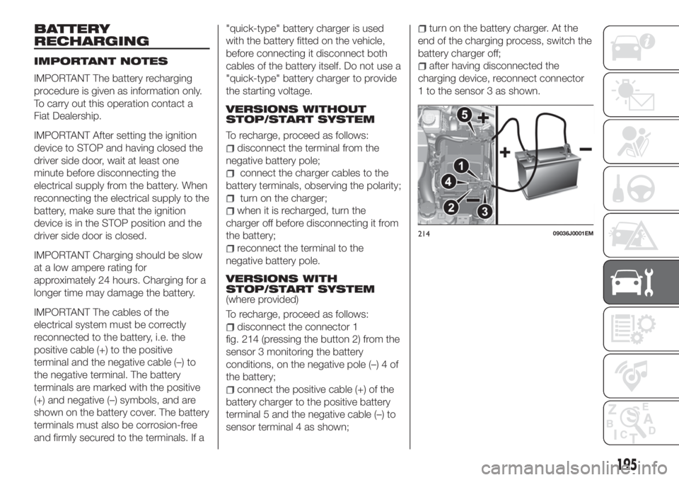
disconnect the connector 1
fig. 214 (pressing the button 2) from the
sensor 3 monitoring the battery
conditions, on the negative pole (–) 4 of
the battery;
connect the positive cable (+) of the
battery charger to the positive battery
terminal 5 and the negative cable (–) to
sensor terminal 4 as shown;
turn on the battery charger. At the
end of the charging process, switch the
battery charger off;
after having disconnected the
charging device, reconnect connector
1 to the sensor 3 as shown.
21409036J0001EM
195