engine FIAT ULYSSE 2007 2.G Owner's Manual
[x] Cancel search | Manufacturer: FIAT, Model Year: 2007, Model line: ULYSSE, Model: FIAT ULYSSE 2007 2.GPages: 254, PDF Size: 3.42 MB
Page 69 of 254
GETTING TO KNOW YOUR CAR
68
The system uses refrig-
erant R134a as it will not
pollute the environment
if it accidentally leaks. Under no
circumstance use other fluids
which are incompatible with the
system’s component parts.
AIR FLOW
The system manual operation has 8
different air capacity levels which are
displayed with half blackening of each
main fan symbol stake.
When the automatic function has
been enabled (AUTO) the air capaci-
ty varies and can be controlled by the
system. This is indicated on the display
by 4 half blackened stakes. It is easier to reach the
wished air temperature
conditions with inside air
recirculation. Anyway, it is better
not to use this function in
rainy/cold days because inside
window misting may increase, es-
pecially if the compressor is off.
You are recommended
to use the inside air recir-
culation function in the
traffic jam (car lines inside or out-
side galleries) to prevent outside
polluted air from getting into the
vehicle. Anyway, do not use this
function when several people are
onboard, to prevent inside win-
dow misting.AUTOMATIC
CLIMATE CONTROL
SYSTEM
The car is fitted with an automatic
climate control system to control tem-
perature, air capacity, distribution and
recirculation according to two defini-
tion levels:
• automatic system called multi-
zone, with split temperature (left/
right) for the first and second row;
• automatic system called three-
zonewith additional rear fans which
can be controlled by the second row
passengers to change the second and
third row vent air capacity.
IMPORTANTManual selections
prevail over automatic selections and
are stored in the memory until the
user activates the system automatic
mode (AUTO). Manual settings are
stored when the engine is turned off
and restored when the engine is start-
ed again.
Page 70 of 254
GETTING TO KNOW YOUR CAR
69
IMPORTANTWhen the engine is
started with the climate control sys-
tem in automatic mode and the ex-
ternal temperature is very low, the fan
may not be activated. Do not consid-
er it a malfunction; the system will re-
store the normal operation as soon as
the temperature threshold set by the
system is reached.
AIR DISTRIBUTION
Air distribution options, controlled
automatically or manually, are the fol-
lowing:
– ventilation (front)
– bilevel (front/feet)
– feet
– windscreen/feet
– MAX-DEF function.
Air is also delivered to second and
third row seat.Ventilation
The treated air flow passes through
5 front vents placed on the edge and
in the middle of the dashboard. The air
flow can be directed both horizontal-
ly and vertically by adjusting manually
the tab position and the control lever.
Air capacity can be adjusted by ro-
tating the vent sliders.
With this setting the system enables
air capacity variation for the second
and third row.
Bilevel function
The air flow is distributed in the fol-
lowing way: 45% ventilation, 45% feet,
10% windscreen.
With this setting treated air is di-
rected towards the feet of front and
rear seat passengers and towards the
dashboard vents. It also enables air ca-
pacity variation for the second and
third row.Feet
Air is directed towards the feet
through:
– three front vents for the first row
(2 on the driver’s side and 1 on the
passenger’s side);
– four vents on the floor (2 for the
second row and 2 for the third row).
Windscreen/feet
Air is distributed with the same per-
centage to the feet (40%) and wind-
screen vents (40%), but a small per-
centage is devoted to ventilation (20%)
in order to guarantee the passenger
compartment heating and to prevent
frosting.
This type of air distribution is applied
by the climate control system auto-
matic operation, especially when the
external temperature is very low and
it is necessary to direct some warm air
towards the driver’s hands.
Page 75 of 254
GETTING TO KNOW YOUR CAR
74
NClimate control system compres-
sor on/off
OInside air recirculation on/off.
SYSTEM OPERATION
fig. 88-89
The system can be activated in sev-
eral ways:
– turning the main fan slider clock-
wise (L);
– or pressing button A(+/–) or E
(+/–);
– or pressing one of buttons (H, I,
M);
In these three cases the system re-
stores all the operation functions
stored before turning it off.
– or pressing one of buttons B, D,
N; in this case the automatic mode is
selected;– or pressing button G; in this case
the MAX-DEF function is selected.
The system automatically stores the
settings prior to the system switching
off, but it also takes into consideration
the vehicle stop and other external pa-
rameters, i.e.:
– if the engine is turned off for 20
minutes with the same internal tem-
perature, the system is restored keep-
ing the same settings. If in that period
temperature changes considerably, the
system restores the temperature pri-
or to switching off;
– if the engine is turned off for more
than 20 minutes, the system is
switched on in automatic mode, even
it was off before the vehicle stop, with-
out changing the temperature value.SETTINGS fig. 88-89
The user can choose the following
options:
• wished temperature setting:
this is possible pressing button A(+/–)
or E(+/–) and checking the temper-
ature value on the display (C). It is al-
so possible to split temperature and
set different values for the driver and
the passenger; the maximum differ-
ence is 5°C.
Temperature can be increased or de-
creased by setting different steps
which can be viewed on the display:
1°C between 14°C and 18°C and be-
tween 24°C and 28°C, 0.5°C between
18°C and 24°C.
Page 76 of 254
GETTING TO KNOW YOUR CAR
75
• “completely cold” setting: this
option can be selected automatically
by pressing and keeping button A(–)
or E(–) pressed until 14°C are
reached; in this case the system per-
formance is at the highest. With this
option the system works in mono
conditions and the following settings
are active:
– slider turned to “completely cold”;
– air distribution during ventilation;
– maximum air capacity value;
– compressor on;
– automatic recirculation off, even if
it is possible to activate it manually
without leaving the wished setting.• “completely hot” setting: this
option can be selected automatically
by pressing and keeping button A(+)
or E(+) pressed until 28°C are
reached; in this case the system per-
formance is at the highest. The fol-
lowing settings are active as well:
– slider turned to “completely hot”;
– air directed to windscreen/feet or
feet, according to the outside tem-
perature;
– maximum air capacity value;
– compressor controlled by the sys-
tem;
– automatic recirculation closed even
if it possible to activate manually the
open recirculation without leaving the
required setting.• fan speed setting: this is possi-
ble by turning slider L; the wished
speed value is displayed through the
front fan stake blackening C.
IMPORTANTWhen the engine is
started with the climate control sys-
tem in automatic mode (AUTO) and
the external temperature is very low,
the fan may not be activated. Do not
consider it a malfunction; the system
will restore the normal operation as
soon as the temperature threshold set
by the system is reached.
• air distribution selection: this is
possible by pressing altogether H, I,
Mon the central rotating slider L.
Air can be distributed in five
ways: ventilation (front), bilevel
(front/feet), feet, windscreen/feet,
windscreen (MAX-DEF).
Page 79 of 254
GETTING TO KNOW YOUR CAR
78
TURNING THE SYSTEM OFF
The system can be switched off by
turning knurled knob Lanticlockwise
until the car shape is displayed with-
out the fan symbol.
When the system is turned off it
makes the following operations:
– storing of conditions prior to
switching off;
– the graphics on display Cgo off ex-
cept for the car shape;
– the air recirculation is taken to
open position (outside air intake);
– the compressor is excluded;
– the fan is excluded;
– the air is distributed to the wind-
screen;
– the air mixing is in “completely
cold” position.FAILURE INDICATION
If any failures are detected (locked
switches, sensor malfunction, electri-
cal failures, etc.) the system automat-
ically sets the “recovery” mode, which
is displayed by the flashing points sep-
arating the temperature decimals on
the display C. In this case contact a Fi-
at Dealership as soon as possible.
Recovery mode
The system will work in the follow-
ing way:
– driver’s and passenger’s tem-
peratures: aligned and evolving in the
same way;
if buttons Aor Eare locked tem-
perature is set at 21°C by the system;
– main fan, distribution, com-
pressor, recirculation: they work in
automatic mode (AUTO);
– AUTO function:main fan, air dis-
tribution, compressor and air recircu-
lation are automatically controlled by
the system and the impulses on the
relative switches have no effect;– MAX-DEF function: the system
directs air to the windscreen and the
air distribution, compressor, AUTO
and air recirculation switches are not
active, while the main fan and tem-
perature functions are still active;
– REAR function: additional fans
cannot be switched on;
– rear window: cannot be switched
on.
INDEPENDENT ADDITIONAL
HEATER
To improve your comfort, cars with
JTD engines, can be fitted with an in-
dependent additional heater.
After switching the engine off or with
engine idling, the additional heater
could stay on hissing and exhaling
smoke and smell.
Page 80 of 254
GETTING TO KNOW YOUR CAR
79
STEERING COLUMN
STALKS
LEFT-HAND STALK
The left-hand stalk controls most of
the outside lights. If you leave the lights
on when you take the key out of the
ignition an alarm will sound.
Outside lighting is possible with the
ignition key at M.
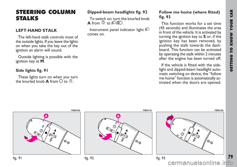
Side lights fig. 91
These lights turn on when you turn
the knurled knob Afrom åto
6.Dipped-beam headlights fig. 92
To switch on: turn the knurled knob
Afrom
6to 2/1.
Instrument panel indicator light 2
comes on.Follow me home (where fitted)
fig. 93
This function works for a set time
(45 seconds) and illuminates the area
in front of the vehicle. It is activated by
turning the ignition key to Sor, if the
ignition key has been removed, by
pushing the stalk towards the dash-
board. This function can be activated
by operating the stalk within 2 minutes
after the engine has been turned off.
If the vehicle is fitted with the side-
light and dipped-beam headlight auto-
matic switching on device, the “follow
me home” function is automatically ac-
tivated when the doors are opened.
fig. 91
F0B0416b
fig. 92
F0B0417b
fig. 93
F0B0418b
Page 82 of 254
GETTING TO KNOW YOUR CAR
81
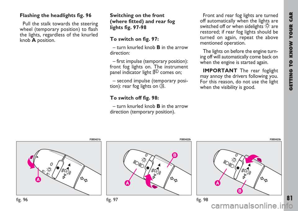
Flashing the headlights fig. 96
Pull the stalk towards the steering
wheel (temporary position) to flash
the lights, regardless of the knurled
knob Aposition.Switching on the front
(where fitted) and rear fog
lights fig. 97-98
To switch on fig. 97:
– turn knurled knob Bin the arrow
direction:
– first impulse (temporary position):
front fog lights on. The instrument
panel indicator light
5comes on;
– second impulse (temporary posi-
tion): rear fog lights on
4.
To switch off fig. 98:
– turn knurled knob Bin the arrow
direction (temporary position).Front and rear fog lights are turned
off automatically when the lights are
switched off or when sidelights
6are
restored; if rear fog lights should be
turned on again, repeat the above
mentioned operation.
The lights on before the engine turn-
ing off will automatically come back on
when the engine is started again.
IMPORTANTThe rear foglight
may annoy the drivers following you.
For this reason, do not use the light
when the visibility is good.
fig. 96
F0B0421b
fig. 97
F0B0422b
fig. 98
F0B0423b
Page 85 of 254
GETTING TO KNOW YOUR CAR
84
When the windscreen wiper is
turned on with the rain sensor already
working, the windscreen wiper wash-
es the windscreen regularly and, at the
end of its operation, the rain sensor
keeps on working automatically.
To switch off the rain sensor turn the
key to Sand when the engine is start-
ed again, the rain sensor will not be
turned on even if the stalk remained
in AUTO position.
To switch on the rain sensor, move
the stalk to another position and then
back to AUTO.The rain sensor can recognize and
automatically adapt to particular
weather conditions which require dif-
ferent operations:
– surface impurities (salt, dirt,…);
– water lines due to worn out wind-
screen wiper blades;
– difference between night and day
(the human eye is particularly annoyed
by the windscreen wet surface at night
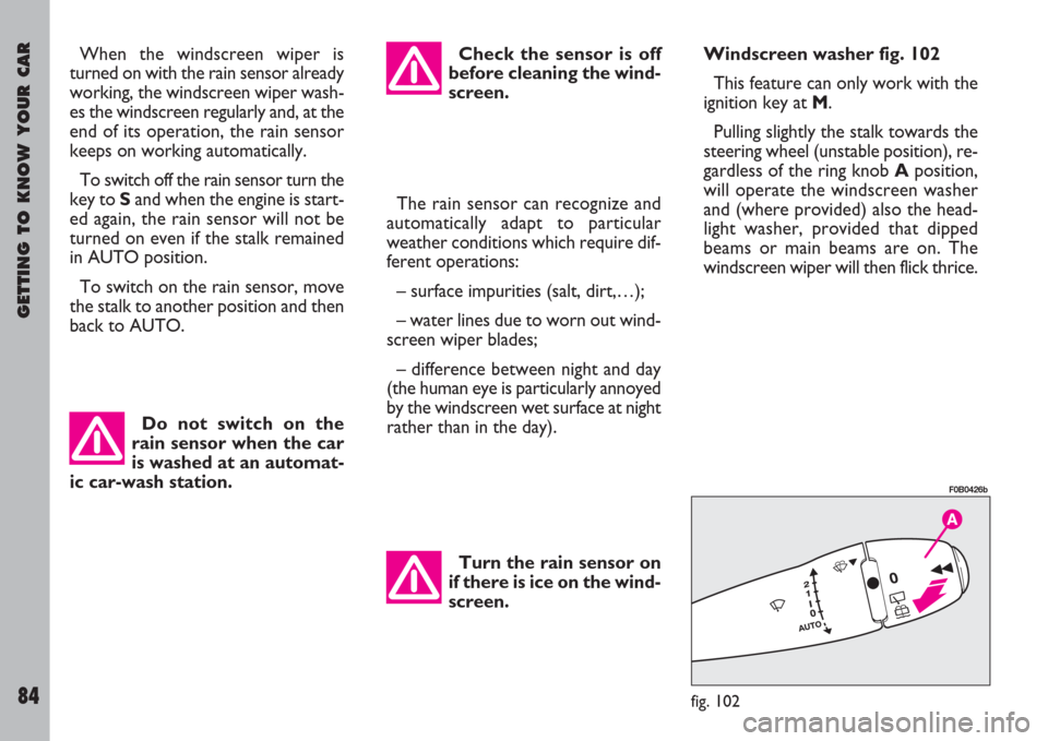
rather than in the day).Windscreen washer fig. 102
This feature can only work with the
ignition key at M.
Pulling slightly the stalk towards the
steering wheel (unstable position), re-
gardless of the ring knob Aposition,
will operate the windscreen washer
and (where provided) also the head-
light washer, provided that dipped
beams or main beams are on. The
windscreen wiper will then flick thrice.
Do not switch on the
rain sensor when the car
is washed at an automat-
ic car-wash station.Check the sensor is off
before cleaning the wind-
screen.
Turn the rain sensor on
if there is ice on the wind-
screen.
fig. 102
F0B0426b
Page 88 of 254
GETTING TO KNOW YOUR CAR
87
FUEL CUT-OFF
SWITCH
This is a safety switch controlled by
the Airbag control unit. Such switch
cuts in on collision and cuts off the fu-
el supply. This results in the engine
stalling.
The multifunction display informs the
driver that the fuel has been cut off
with a dedicated message.If you do not notice fuel leaks
and the vehicle is in a fit state to
continue on its way, proceed as
follows:
– turn the key to S;
– extract the ignition key; rein-
troduce it and start the engine as
usual.
HANDBRAKE
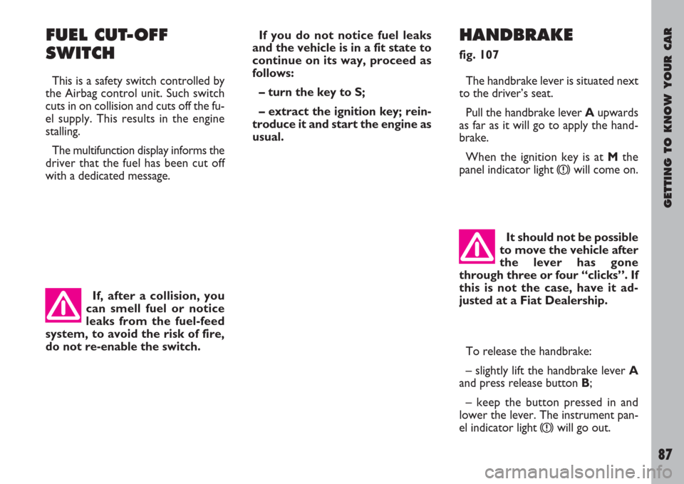
fig. 107
The handbrake lever is situated next
to the driver’s seat.
Pull the handbrake lever Aupwards
as far as it will go to apply the hand-
brake.
When the ignition key is at Mthe
panel indicator light
xwill come on.
If, after a collision, you
can smell fuel or notice
leaks from the fuel-feed
system, to avoid the risk of fire,
do not re-enable the switch.It should not be possible
to move the vehicle after
the lever has gone
through three or four “clicks”. If
this is not the case, have it ad-
justed at a Fiat Dealership.
To release the handbrake:
– slightly lift the handbrake lever A
and press release button B;
– keep the button pressed in and
lower the lever. The instrument pan-
el indicator light
xwill go out.
Page 89 of 254
GETTING TO KNOW YOUR CAR
88
To prevent the vehicle from moving
accidentally, release the handbrake
with the foot brake pedal depressed.
IMPORTANTThe handbrake
lever A is fitted with a safety device
which prevents the handbrake disen-
gaging when button Bis pressed with
the lever pulled. Therefore, to release
the handbrake, not only press button
B, but also pull the lever Aupwards
so that the safety device is released,
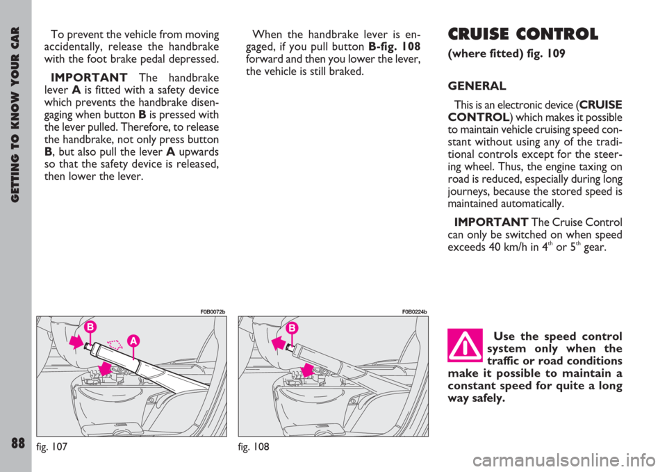
then lower the lever.When the handbrake lever is en-
gaged, if you pull button B-fig. 108
forward and then you lower the lever,
the vehicle is still braked.CRUISE CONTROL
(where fitted) fig. 109
GENERAL
This is an electronic device (CRUISE
CONTROL) which makes it possible
to maintain vehicle cruising speed con-
stant without using any of the tradi-
tional controls except for the steer-
ing wheel. Thus, the engine taxing on
road is reduced, especially during long
journeys, because the stored speed is
maintained automatically.
IMPORTANTThe Cruise Control
can only be switched on when speed
exceeds 40 km/h in 4
thor 5thgear.
fig. 107
F0B0072b
fig. 108
F0B0224b
Use the speed control
system only when the
traffic or road conditions
make it possible to maintain a
constant speed for quite a long
way safely.