stop start FIAT UNO 1983 Service User Guide
[x] Cancel search | Manufacturer: FIAT, Model Year: 1983, Model line: UNO, Model: FIAT UNO 1983Pages: 303, PDF Size: 10.36 MB
Page 94 of 303
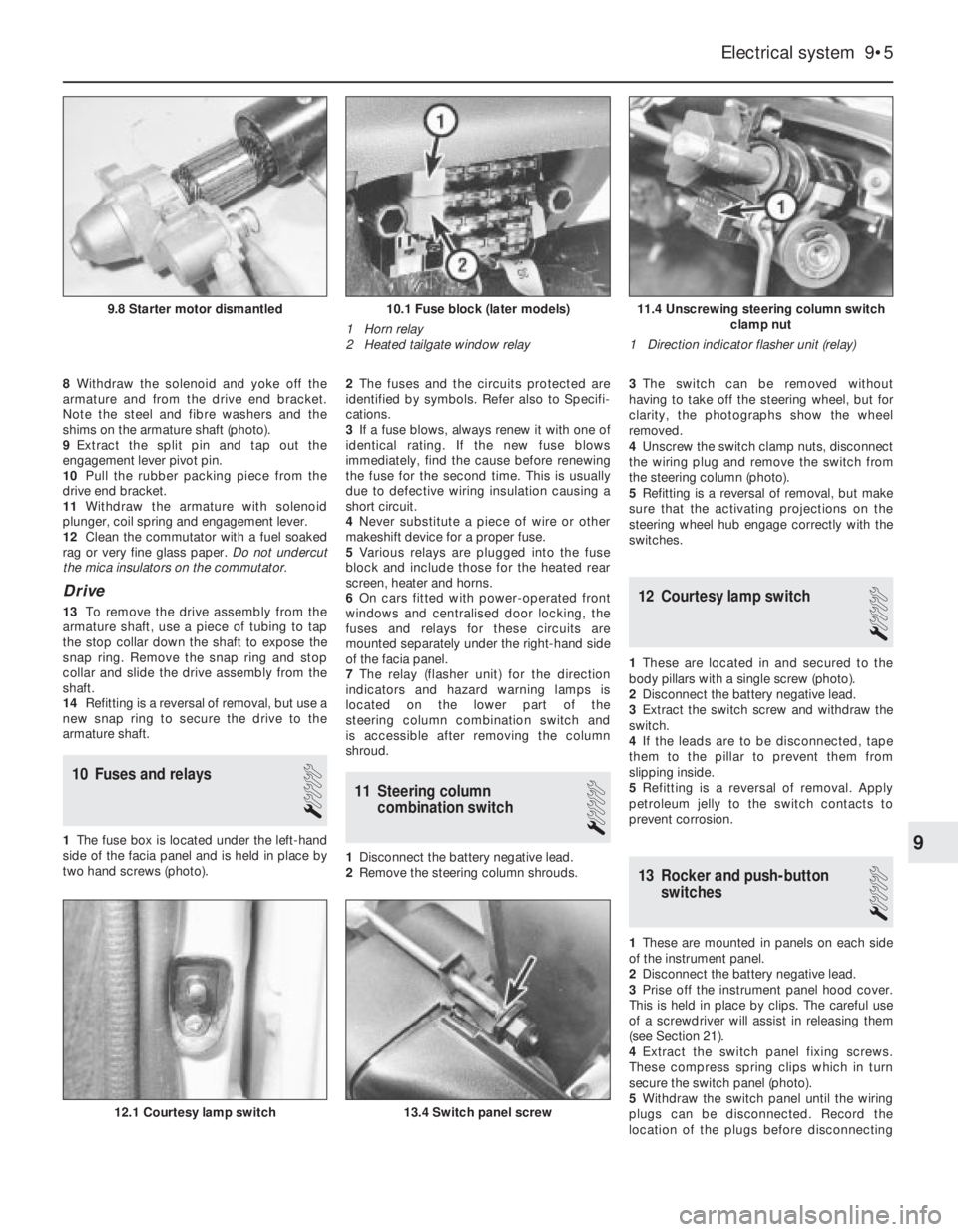
8Withdraw the solenoid and yoke off the
armature and from the drive end bracket.
Note the steel and fibre washers and the
shims on the armature shaft (photo).
9Extract the split pin and tap out the
engagement lever pivot pin.
10Pull the rubber packing piece from the
drive end bracket.
11Withdraw the armature with solenoid
plunger, coil spring and engagement lever.
12Clean the commutator with a fuel soaked
rag or very fine glass paper. Do not undercut
the mica insulators on the commutator.
Drive
13To remove the drive assembly from the
armature shaft, use a piece of tubing to tap
the stop collar down the shaft to expose the
snap ring. Remove the snap ring and stop
collar and slide the drive assembly from the
shaft.
14Refitting is a reversal of removal, but use a
new snap ring to secure the drive to the
armature shaft.
10 Fuses and relays
1
1The fuse box is located under the left-hand
side of the facia panel and is held in place by
two hand screws (photo).2The fuses and the circuits protected are
identified by symbols. Refer also to Specifi-
cations.
3If a fuse blows, always renew it with one of
identical rating. If the new fuse blows
immediately, find the cause before renewing
the fuse for the second time. This is usually
due to defective wiring insulation causing a
short circuit.
4Never substitute a piece of wire or other
makeshift device for a proper fuse.
5Various relays are plugged into the fuse
block and include those for the heated rear
screen, heater and horns.
6On cars fitted with power-operated front
windows and centralised door locking, the
fuses and relays for these circuits are
mounted separately under the right-hand side
of the facia panel.
7The relay (flasher unit) for the direction
indicators and hazard warning lamps is
located on the lower part of the
steering column combination switch and
is accessible after removing the column
shroud.
11 Steering column
combination switch
1
1Disconnect the battery negative lead.
2Remove the steering column shrouds. 3The switch can be removed without
having to take off the steering wheel, but for
clarity, the photographs show the wheel
removed.
4Unscrew the switch clamp nuts, disconnect
the wiring plug and remove the switch from
the steering column (photo).
5Refitting is a reversal of removal, but make
sure that the activating projections on the
steering wheel hub engage correctly with the
switches.
12 Courtesy lamp switch
1
1These are located in and secured to the
body pillars with a single screw (photo).
2Disconnect the battery negative lead.
3Extract the switch screw and withdraw the
switch.
4If the leads are to be disconnected, tape
them to the pillar to prevent them from
slipping inside.
5Refitting is a reversal of removal. Apply
petroleum jelly to the switch contacts to
prevent corrosion.
13 Rocker and push-button
switches
1
1These are mounted in panels on each side
of the instrument panel.
2Disconnect the battery negative lead.
3Prise off the instrument panel hood cover.
This is held in place by clips. The careful use
of a screwdriver will assist in releasing them
(see Section 21).
4Extract the switch panel fixing screws.
These compress spring clips which in turn
secure the switch panel (photo).
5Withdraw the switch panel until the wiring
plugs can be disconnected. Record the
location of the plugs before disconnecting
Electrical system 9•5
11.4 Unscrewing steering column switch
clamp nut
1 Direction indicator flasher unit (relay)10.1 Fuse block (later models)
1 Horn relay
2 Heated tailgate window relay9.8 Starter motor dismantled
13.4 Switch panel screw12.1 Courtesy lamp switch
9
Page 101 of 303
3The centralised door locking system can
operate independently of the key.
4To gain access to the lock solenoid and
linkage, remove the front door trim panel as
described in Chapter 12.
5Disconnect the battery negative lead.
6Disconnect the electrical wiring plugs from
the solenoid within the door cavity.
7Disconnect the solenoid from the lock lever
by removing the clip.
8Unscrew the two bolts which secure the
solenoid to the door and remove it.
9Renew the solenoid or switch as necessary.
10Refitting is a reversal of removal.
11Refer to Section 10 for details of system
fuses and relays.
33 Economy gauge
(Econometer)
2
1This device is fitted to ES (energy saving)
models and indicates to the driver the fuel
consumption (in litres per 100 km) coupled
with a needle which moves over coloured
sections of a dial to make the driver aware
that his method of driving is either conducive
to high or low fuel consumption. Refer to
Chapter 3, Section 16.
2The device is essentially a vacuum gauge
which also incorporates a warning lamp to
indicate to the driver when a change of gear is
required.
3A fuel cut-out valve (see Chapter 3, Sec-
tion 11) is used in conjunction with the
economy gauge so that when the accelerator
pedal is released during a pre-determined
engine speed range, fuel supply to the engine
is stopped, but resumes when the engine
speed falls below the specified range.
LED (light emitter diode)
4The gearchange indicator will only light up
at engine speeds in excess of 2000 rev/min
for vacuum pressures up to 600 mm Hg in 1st,
2nd and 3rd speed gears and for vacuum
pressures up to 676 mm Hg in 4th speedgear. The light will not come on if 5th speed
gear is engaged or if the coolant temperature
is below 55ºC.
5There is a two second delay in the light
coming on to prevent it operating during rapid
acceleration in a low gear.
6If the LED light comes on during
deceleration it should be ignored.
Fault finding
7A faulty economy gauge should be checked
in the following way.
8Refer to Section 21 and remove the
instrument panel.
9Disconnect the economy gauge L
connector and then connect a test lamp
between the BN cable contact and earth. If
the lamp comes on then the gauge supply
circuit is not open. If the lamp does not come
on, check all connections in the supply cable
which comes from the interconnecting unit of
the electrical system, also Fuse No 12.
10Now connect a voltmeter between the
white cable and earth. Check the voltage with
the engine not running, but the ignition
switched on. It should be between 0.7 and
0.9 volt. If the reading varies considerably
from that specified, check the connections
between the economy gauge and the fuel
cut-out device control unit. If the fault cannot
be rectified, renew the ignition control unit
(Digiplex system, see Chapter 4).
11Now check the closed throttle valve plate
switch by connecting a voltmeter between the
brown and BN cables of the L connector. With
the valve plate open, there should be no
reading, but with it open, voltage should be
indicated.
12Failure to conform as described will be
due to a faulty earth in the switch or a faulty
fuel cut-out device control unit.
13A further test of the throttle valve plate
switch may be carried out by disconnecting
the multi-plug from the fuel cut-out device
control unit.
14Connect a test lamp to contact 4 (positive
battery terminal). The lamp should come on,
when the engine is idling or the accelerator
released. If it does not, renew the throttle
valve plate switch.15Connect a tachometer to the brown/white
cable contact in the L connector and record
the engine speed with the engine running. If
no reading is obtained, renew the Digiplex
ignition control unit which must be faulty.
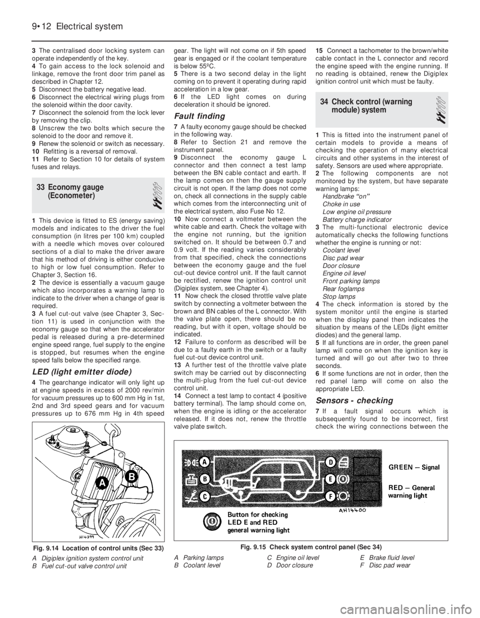
34 Check control (warning
module) system
2
1This is fitted into the instrument panel of
certain models to provide a means of
checking the operation of many electrical
circuits and other systems in the interest of
safety. Sensors are used where appropriate.
2The following components are not
monitored by the system, but have separate
warning lamps:
Handbrake “on”
Choke in use
Low engine oil pressure
Battery charge indicator
3The multi-functional electronic device
automatically checks the following functions
whether the engine is running or not:
Coolant level
Disc pad wear
Door closure
Engine oil level
Front parking lamps
Rear foglamps
Stop lamps
4The check information is stored by the
system monitor until the engine is started
when the display panel then indicates the
situation by means of the LEDs (light emitter
diodes) and the general lamp.
5If all functions are in order, the green panel
lamp will come on when the ignition key is
turned and will go out after two to three
seconds.
6If some functions are not in order, then the
red panel lamp will come on also the
appropriate LED.
Sensors - checking
7If a fault signal occurs which is
subsequently found to be incorrect, first
check the wiring connections between the
9•12 Electrical system
Fig. 9.15 Check system control panel (Sec 34)
A Parking lamps
B Coolant levelC Engine oil level
D Door closureE Brake fluid level
F Disc pad wearFig. 9.14 Location of control units (Sec 33)
A Digiplex ignition system control unit
B Fuel cut-out valve control unit
Page 116 of 303
affected area with rust-inhibiting paint, if the
back of the rusted area is accessible, treat
this also.
Before filling can take place, it will be
necessary to block the hole in some way. This
can be achieved by the use of aluminium or
plastic mesh, or aluminium tape.
Aluminium or plastic mesh, or glass-fibre
matting, is probably the best material to use
for a large hole. Cut a piece to the
approximate size and shape of the hole to be
filled, then position it in the hole so that its
edges are below the level of the surrounding
bodywork. It can be retained in position by
several blobs of filler paste around its
periphery.
Aluminium tape should be used for small or
very narrow holes. Pull a piece off the roll, trim
it to the approximate size and shape required,
then pull off the backing paper (if used) and
stick the tape over the hole; it can be
overlapped if the thickness of one piece is
insufficient. Burnish down the edges of the
tape with the handle of a screwdriver or
similar, to ensure that the tape is securely
attached to the metal underneath.
Bodywork repairs - filling and
respraying
Before using this Section, see the Sections
on dent, deep scratch, rust holes and gash
repairs.
Many types of bodyfiller are available, but
generally speaking, those proprietary kits
which contain a tin of filler paste and a tube of
resin hardener are best for this type of repair. A
wide, flexible plastic or nylon applicator will be
found invaluable for imparting a smooth and
well-contoured finish to the surface of the filler.
Mix up a little filler on a clean piece of card
or board - measure the hardener carefully
(follow the maker’s instructions on the pack),
otherwise the filler will set too rapidly or too
slowly. Using the applicator, apply the filler
paste to the prepared area; draw the
applicator across the surface of the filler to
achieve the correct contour and to level the
surface. As soon as a contour that
approximates to the correct one is achieved,
stop working the paste - if you carry on too
long, the paste will become sticky and begin
to “pick-up” on the applicator. Continue to
add thin layers of filler paste at 20-minute
intervals, until the level of the filler is just
proud of the surrounding bodywork.
Once the filler has hardened, the excess
can be removed using a metal plane or file.
From then on, progressively-finer grades of
abrasive paper should be used, starting with a
40-grade production paper, and finishing with
a 400-grade wet-and-dry paper. Always wrap
the abrasive paper around a flat rubber, cork,
or wooden block - otherwise the surface of
the filler will not be completely flat. During the
smoothing of the filler surface, the wet-and-
dry paper should be periodically rinsed in
water. This will ensure that a very smooth
finish is imparted to the filler at the final stage.At this stage, the “dent” should be
surrounded by a ring of bare metal, which in
turn should be encircled by the finely
“feathered” edge of the good paintwork.
Rinse the repair area with clean water, until all
of the dust produced by the rubbing-down
operation has gone.
Spray the whole area with a light coat of
primer - this will show up any imperfections in
the surface of the filler. Repair these
imperfections with fresh filler paste or
bodystopper, and once more smooth the
surface with abrasive paper. Repeat this
spray-and-repair procedure until you are
satisfied that the surface of the filler, and the
feathered edge of the paintwork, are perfect.
Clean the repair area with clean water, and
allow to dry fully.
The repair area is now ready for final
spraying. Paint spraying must be carried out
in a warm, dry, windless and dust-free
atmosphere. This condition can be created
artificially if you have access to a large indoor
working area, but if you are forced to work in
the open, you will have to pick your day very
carefully. If you are working indoors, dousing
the floor in the work area with water will help
to settle the dust which would otherwise be in
the atmosphere. If the repair area is confined
to one body panel, mask off the surrounding
panels; this will help to minimise the effects of
a slight mis-match in paint colours. Bodywork
fittings (eg chrome strips, door handles etc)
will also need to be masked off. Use genuine
masking tape, and several thicknesses of
newspaper, for the masking operations.
Before commencing to spray, agitate the
aerosol can thoroughly, then spray a test area
(an old tin, or similar) until the technique is
mastered. Cover the repair area with a thick
coat of primer; the thickness should be built
up using several thin layers of paint, rather
than one thick one. Using 400-grade wet-and-
dry paper, rub down the surface of the primer
until it is really smooth. While doing this, the
work area should be thoroughly doused withwater, and the wet-and-dry paper periodically
rinsed in water. Allow to dry before spraying
on more paint.
Spray on the top coat, again building up the
thickness by using several thin layers of paint.
Start spraying at one edge of the repair area,
and then, using a side-to-side motion, work
until the whole repair area and about 2 inches
of the surrounding original paintwork is
covered. Remove all masking material 10 to 15
minutes after spraying on the final coat of
paint.
Allow the new paint at least two weeks to
harden, then, using a paintwork renovator, or
a very fine cutting paste, blend the edges of
the paint into the existing paintwork. Finally,
apply wax polish.
5 Major body damage-
repair
5
1Major repair to the body should be left to
your Fiat dealer or specialist body repairer.
2Special jigs and alignment gauges are
required without which steering and
suspension characteristics may be incorrect
after the repairs are completed.
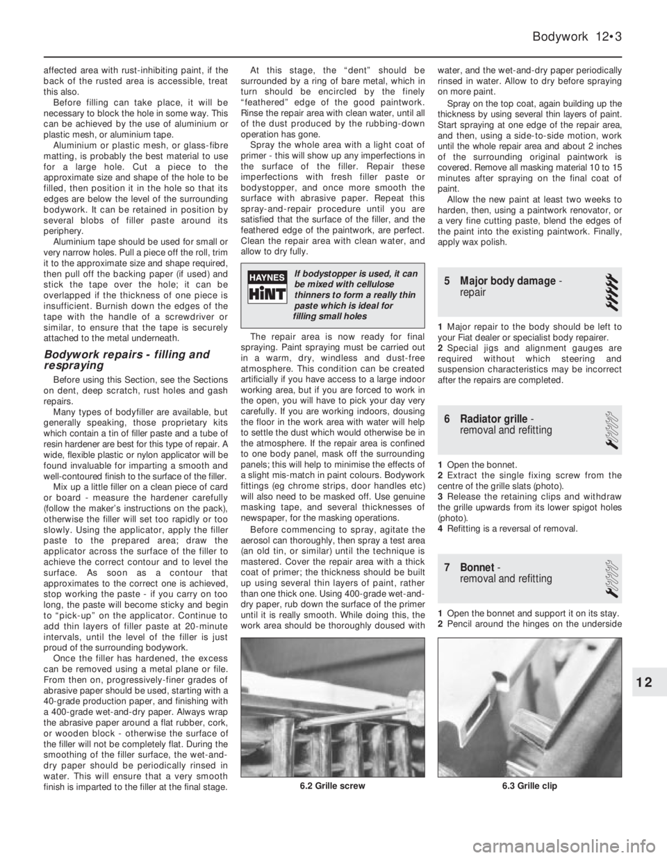
6 Radiator grille-
removal and refitting
1
1Open the bonnet.
2Extract the single fixing screw from the
centre of the grille slats (photo).
3Release the retaining clips and withdraw
the grille upwards from its lower spigot holes
(photo).
4Refitting is a reversal of removal.
7 Bonnet-
removal and refitting
1
1Open the bonnet and support it on its stay.
2Pencil around the hinges on the underside
Bodywork 12•3
12
If bodystopper is used, it can
be mixed with cellulose
thinners to form a really thin
paste which is ideal for
filling small holes
6.3 Grille clip6.2 Grille screw
Page 162 of 303
Initial start-up after major
overhaul
28Refer to Chapter 1, Section 45, but note
that an oil pressure gauge is fitted to indicate
oil pressure.
29Check the ignition static timing as
described in Section 10.
30Check the engine idle speed and CO level
as described in Section 9.
7 Engine-
1372 cc ie and 1372 cc
Turbo ie
PART A: GENERAL
Description
1The 1372 cc engine is similar in design to
the OHC engine fitted to the FIAT Tipo
variants. The engine is of four-cylinder, in-line,
overhead camshaft type, mounted
transversely at the front of the vehicle.
2The crankshaft runs in five main bearings.
Thrustwashers are fitted to the rear (flywheel
end) main bearing in order to control
crankshaft endfloat.
3The connecting rods are attached to the
crankshaft by horizontally split shell-type
big-end bearings. The pistons are attached to
the connecting rods by fully-floating gudgeon
pins which are secured by circlips. The
aluminium alloy pistons are fitted with three
piston rings: two compression rings and an oil
control ring.
4The camshaft is driven by a toothed belt
and operates the valves via bucket and shim
type cam followers. The camshaft is located in
a separate housing on top of the cylinder
head.
5The inlet and exhaust valves are each
closed by double valve springs, and operate
in guides pressed into the cylinder head.
6The auxiliary shaft, which is also driven by
the toothed belt, drives the oil pump.
7Lubrication is by means of a gear type
pump which draws oil through a strainer
located in the sump, and forces it through a
full-flow filter into the engine oil galleries fromwhere it is distributed to the crankshaft,
camshaft and auxiliary shaft. The big-end
bearings are supplied with oil via internal
drillings in the crankshaft. The undersides of
the pistons are cooled by oil spray nozzles
located in each main bearing location in the
crankcase.
8A crankcase ventilation system is
employed, whereby piston blow-by gases are
drawn via an oil separator into the air cleaner,
from where they are drawn into the inlet
manifold and re-burnt with fresh air/fuel
mixture.
9The 1372 cc ie engine is fitted with a Bosch
Mono-Jetronic single point fuel injection (SPi)
system. Whilst the higher performance
1372 cc Turbo ie engine is fitted with a Bosch
L3.1 (L3.2 from 1992) Jetronic multi-point
injection (MPi) system and turbocharger with
intercooler and oil cooling. The L3.2 system
models are fitted with catalytic converters.
Maintenanceª
10At the intervals specified in Section 3 or
“Routine maintenance” at the beginning of
this Manual, carry out the following tasks.
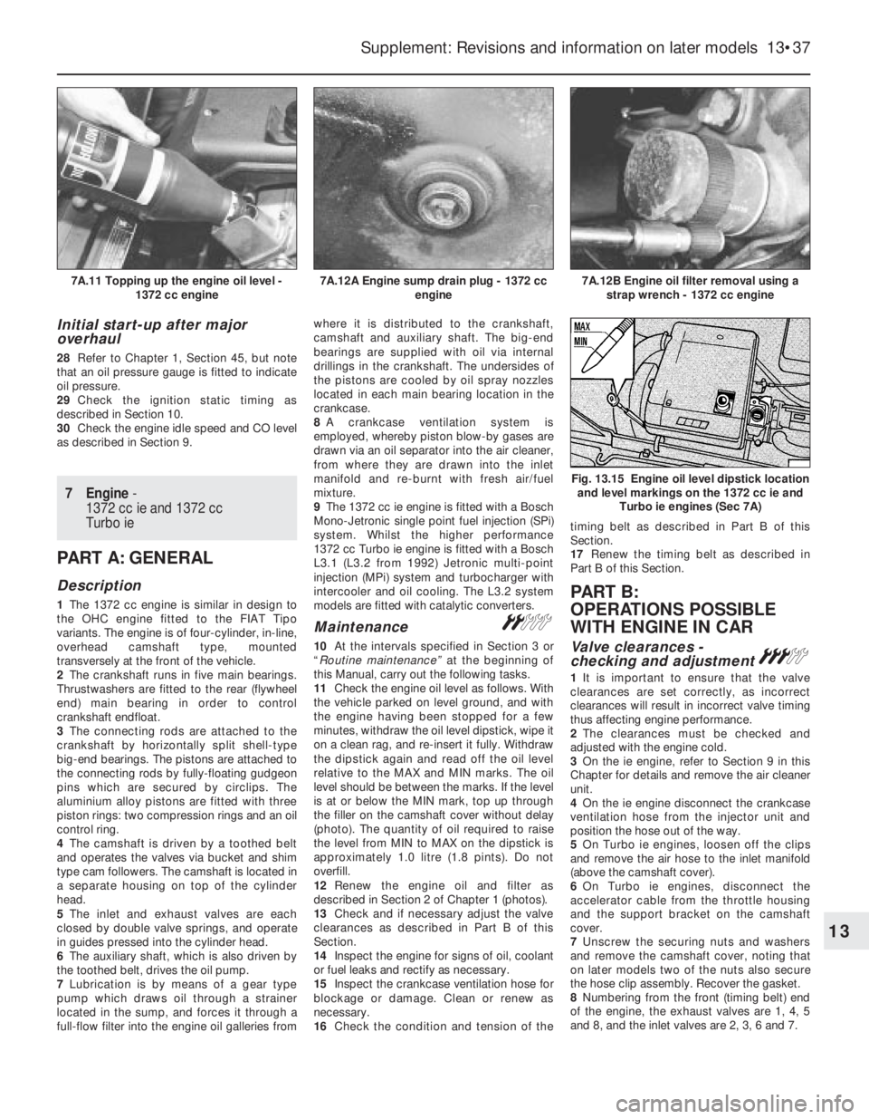
11Check the engine oil level as follows. With
the vehicle parked on level ground, and with
the engine having been stopped for a few
minutes, withdraw the oil level dipstick, wipe it
on a clean rag, and re-insert it fully. Withdraw
the dipstick again and read off the oil level
relative to the MAX and MIN marks. The oil
level should be between the marks. If the level
is at or below the MIN mark, top up through
the filler on the camshaft cover without delay
(photo). The quantity of oil required to raise
the level from MIN to MAX on the dipstick is
approximately 1.0 litre (1.8 pints). Do not
overfill.
12Renew the engine oil and filter as
described in Section 2 of Chapter 1 (photos).
13Check and if necessary adjust the valve
clearances as described in Part B of this
Section.
14Inspect the engine for signs of oil, coolant
or fuel leaks and rectify as necessary.
15Inspect the crankcase ventilation hose for
blockage or damage. Clean or renew as
necessary.
16Check the condition and tension of thetiming belt as described in Part B of this
Section.
17Renew the timing belt as described in
Part B of this Section.
PART B:
OPERATIONS POSSlBLE
WITH ENGINE IN CAR
Valve clearances -
checking and adjustment#
1It is important to ensure that the valve
clearances are set correctly, as incorrect
clearances will result in incorrect valve timing
thus affecting engine performance.
2The clearances must be checked and
adjusted with the engine cold.
3On the ie engine, refer to Section 9 in this
Chapter for details and remove the air cleaner
unit.
4On the ie engine disconnect the crankcase
ventilation hose from the injector unit and
position the hose out of the way.
5On Turbo ie engines, loosen off the clips
and remove the air hose to the inlet manifold
(above the camshaft cover).
6On Turbo ie engines, disconnect the
accelerator cable from the throttle housing
and the support bracket on the camshaft
cover.
7Unscrew the securing nuts and washers
and remove the camshaft cover, noting that
on later models two of the nuts also secure
the hose clip assembly. Recover the gasket.
8Numbering from the front (timing belt) end
of the engine, the exhaust valves are 1, 4, 5
and 8, and the inlet valves are 2, 3, 6 and 7.
Supplement: Revisions and information on later models 13•37
7A.12B Engine oil filter removal using a
strap wrench - 1372 cc engine7A.12A Engine sump drain plug - 1372 cc
engine7A.11 Topping up the engine oil level -
1372 cc engine
Fig. 13.15 Engine oil level dipstick location
and level markings on the 1372 cc ie and
Turbo ie engines (Sec 7A)
13
Page 182 of 303
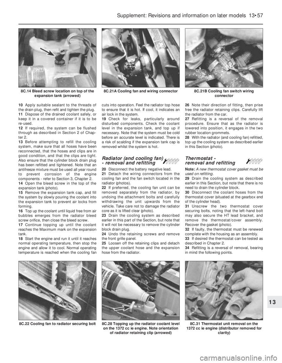
10Apply suitable sealant to the threads of
the drain plug, then refit and tighten the plug.
11Dispose of the drained coolant safely, or
keep it in a covered container if it is to be
re-used.
12If required, the system can be flushed
through as described in Section 2 of Chap-
ter 2.
13Before attempting to refill the cooling
system, make sure that all hoses have been
reconnected, that the hoses and clips are in
good condition, and that the clips are tight.
Also ensure that the cylinder block drain plug
has been refitted and tightened. Note that an
antifreeze mixture must be used all year round
to prevent corrosion of the engine
components - refer to Section 3, Chapter 2.
14Open the bleed screw in the top of the
expansion tank (photo).
15Remove the expansion tank cap, and fill
the system by slowly pouring the coolant into
the expansion tank to prevent air locks from
forming.
16Top up the coolant until liquid free from air
bubbles emerges from the radiator bleed
screw orifice, then close the bleed screw.
17Continue topping up until the coolant
reaches the Maximum mark on the expansion
tank.
18Start the engine and run it until it reaches
normal operating temperature, then stop the
engine and allow it to cool. Normal operating
temperature is reached when the cooling fancuts into operation. Feel the radiator top hose
to ensure that it is hot. If cool, it indicates an
air lock in the system.
19Check for leaks, particularly around
disturbed components. Check the coolant
level in the expansion tank, and top up if
necessary. Note that the system must be cold
before an accurate level is indicated. There is
a risk of scalding if the expansion tank cap is
removed whilst the system is hot.
Radiator (and cooling fan)
- removal and refitting Á
20Disconnect the battery negative lead.
21Detach the wiring connectors from the
cooling fan and the fan switch located in the
radiator (photos).
22If preferred, the cooling fan unit can be
removed separately from the radiator, by
undoing the attachment bolts and carefully
withdrawing the unit upwards from the
vehicle. Take care not to damage the radiator
core as it is lifted clear (photo).
23Drain the cooling system as described
earlier in this part of the Section, but note that
it will not be necessary to remove the cylinder
block drain plug.
24Undo the retaining screws and remove
the front grille panel.
25Loosen off the retaining clips and detach
the upper coolant hose and the expansion
hose from the radiator.26Note their direction of fitting, then prise
free the radiator retaining clips. Carefully lift
the radiator from the car.
27Refitting is a reversal of the removal
procedure. Ensure that as the radiator is
lowered into position, it engages in the two
rubber location grommets.
28With the radiator (and cooling fan) refitted,
top up the cooling system as described earlier
in this Section (photo).
Thermostat -
removal and refitting Á
Note: A new thermostat cover gasket must be
used on refitting.
29Drain the cooling system as described
earlier in this Section, but note that there is no
need to drain the cylinder block.
30Disconnect the coolant hoses from the
thermostat cover (situated at the gearbox end
of the cylinder head).
31Unscrew the two thermostat cover
securing bolts, noting that the left-hand bolt
may also secure the HT lead bracket, and
remove the thermostat/cover assembly.
Recover the gasket (photo).
32If faulty, the thermostat must be renewed
complete with the housing as an assembly.
33If desired the thermostat can be tested as
described in Chapter 2.
34Refitting is a reversal of removal, bearing
in mind the following points.
Supplement: Revisions and information on later models 13•57
8C.21B Cooling fan switch wiring
connector8C.21A Cooling fan and wiring connector8C.14 Bleed screw location on top of the
expansion tank (arrowed)
8C.31 Thermostat unit removal on the
1372 cc ie engine (distributor removed for
clarity)8C.28 Topping up the radiator coolant level
on the 1372 cc ie engine. Note orientation
of radiator retaining clip (arrowed)8C.22 Cooling fan to radiator securing bolt
13
Page 200 of 303
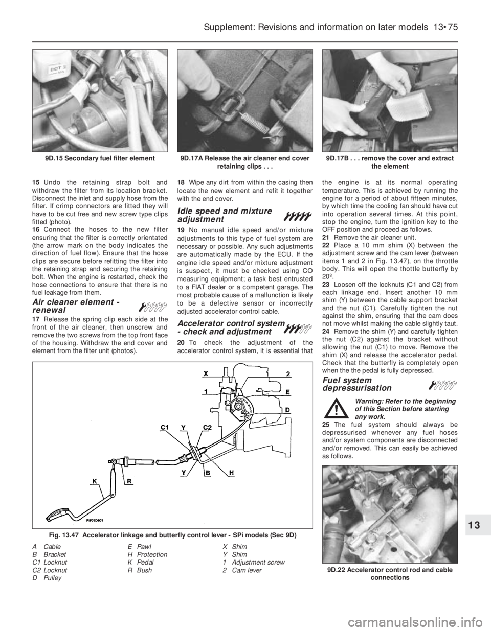
15Undo the retaining strap bolt and
withdraw the filter from its location bracket.
Disconnect the inlet and supply hose from the
filter. If crimp connectors are fitted they will
have to be cut free and new screw type clips
fitted (photo).
16Connect the hoses to the new filter
ensuring that the filter is correctly orientated
(the arrow mark on the body indicates the
direction of fuel flow). Ensure that the hose
clips are secure before refitting the filter into
the retaining strap and securing the retaining
bolt. When the engine is restarted, check the
hose connections to ensure that there is no
fuel leakage from them.
Air cleaner element -
renewalÁ
17Release the spring clip each side at the
front of the air cleaner, then unscrew and
remove the two screws from the top front face
of the housing. Withdraw the end cover and
element from the filter unit (photos).18Wipe any dirt from within the casing then
locate the new element and refit it together
with the end cover.
Idle speed and mixture
adjustment°
19No manual idle speed and/or mixture
adjustments to this type of fuel system are
necessary or possible. Any such adjustments
are automatically made by the ECU. If the
engine idle speed and/or mixture adjustment
is suspect, it must be checked using CO
measuring equipment; a task best entrusted
to a FIAT dealer or a competent garage. The
most probable cause of a malfunction is likely
to be a defective sensor or incorrectly
adjusted accelerator control cable.
Accelerator control system
- check and adjustment#
20To check the adjustment of the
accelerator control system, it is essential thatthe engine is at its normal operating
temperature. This is achieved by running the
engine for a period of about fifteen minutes,
by which time the cooling fan should have cut
into operation several times. At this point,
stop the engine, turn the ignition key to the
OFF position and proceed as follows.
21Remove the air cleaner unit.
22Place a 10 mm shim (X) between the
adjustment screw and the cam lever (between
items 1 and 2 in Fig. 13.47), on the throttle
body. This will open the thottle butterfly by
20º.
23Loosen off the locknuts (C1 and C2) from
each linkage end. Insert another 10 mm
shim (Y) between the cable support bracket
and the nut (C1). Carefully tighten the nut
against the shim, ensuring that the cam does
not move whilst making the cable slightly taut.
24Remove the shim (Y) and carefully tighten
the nut (C2) against the bracket without
allowing the nut (C1) to move. Remove the
shim (X) and release the accelerator pedal.
Check that the butterfly is completely open
when the the pedal is fully depressed.
Fuel system
depressurisationÁ
Warning: Refer to the beginning
of this Section before starting
any work.
25The fuel system should always be
depressurised whenever any fuel hoses
and/or system components are disconnected
and/or removed. This can easily be achieved
as follows.
Supplement: Revisions and information on later models 13•75
9D.17B . . . remove the cover and extract
the element9D.17A Release the air cleaner end cover
retaining clips . . .9D.15 Secondary fuel filter element
9D.22 Accelerator control rod and cable
connections
A Cable
B Bracket
C1 Locknut
C2 Locknut
D PulleyE Pawl
H Protection
K Pedal
R BushX Shim
Y Shim
1 Adjustment screw
2 Cam lever
13
Fig. 13.47 Accelerator linkage and butterfly control lever - SPi models (Sec 9D)
Page 201 of 303
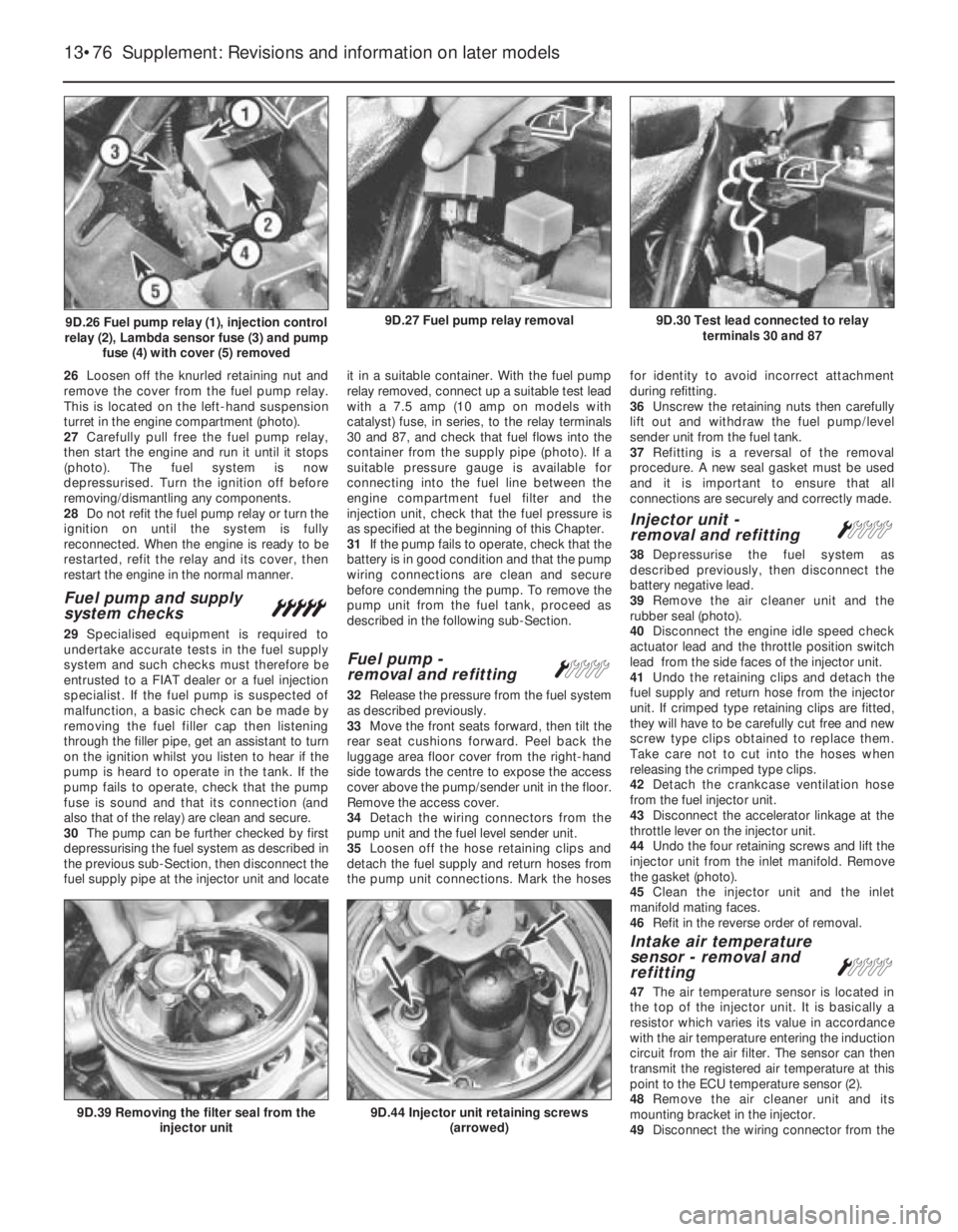
26Loosen off the knurled retaining nut and
remove the cover from the fuel pump relay.
This is located on the left-hand suspension
turret in the engine compartment (photo).
27Carefully pull free the fuel pump relay,
then start the engine and run it until it stops
(photo). The fuel system is now
depressurised. Turn the ignition off before
removing/dismantling any components.
28Do not refit the fuel pump relay or turn the
ignition on until the system is fully
reconnected. When the engine is ready to be
restarted, refit the relay and its cover, then
restart the engine in the normal manner.
Fuel pump and supply
system checks°
29Specialised equipment is required to
undertake accurate tests in the fuel supply
system and such checks must therefore be
entrusted to a FIAT dealer or a fuel injection
specialist. If the fuel pump is suspected of
malfunction, a basic check can be made by
removing the fuel filler cap then listening
through the filler pipe, get an assistant to turn
on the ignition whilst you listen to hear if the
pump is heard to operate in the tank. If the
pump fails to operate, check that the pump
fuse is sound and that its connection (and
also that of the relay) are clean and secure.
30The pump can be further checked by first
depressurising the fuel system as described in
the previous sub-Section, then disconnect the
fuel supply pipe at the injector unit and locateit in a suitable container. With the fuel pump
relay removed, connect up a suitable test lead
with a 7.5 amp (10 amp on models with
catalyst) fuse, in series, to the relay terminals
30 and 87, and check that fuel flows into the
container from the supply pipe (photo). If a
suitable pressure gauge is available for
connecting into the fuel line between the
engine compartment fuel filter and the
injection unit, check that the fuel pressure is
as specified at the beginning of this Chapter.
31If the pump fails to operate, check that the
battery is in good condition and that the pump
wiring connections are clean and secure
before condemning the pump. To remove the
pump unit from the fuel tank, proceed as
described in the following sub-Section.
Fuel pump -
removal and refittingÁ
32Release the pressure from the fuel system
as described previously.
33Move the front seats forward, then tilt the
rear seat cushions forward. Peel back the
luggage area floor cover from the right-hand
side towards the centre to expose the access
cover above the pump/sender unit in the floor.
Remove the access cover.
34Detach the wiring connectors from the
pump unit and the fuel level sender unit.
35Loosen off the hose retaining clips and
detach the fuel supply and return hoses from
the pump unit connections. Mark the hosesfor identity to avoid incorrect attachment
during refitting.
36Unscrew the retaining nuts then carefully
lift out and withdraw the fuel pump/level
sender unit from the fuel tank.
37Refitting is a reversal of the removal
procedure. A new seal gasket must be used
and it is important to ensure that all
connections are securely and correctly made.
Injector unit -
removal and refittingÁ
38Depressurise the fuel system as
described previously, then disconnect the
battery negative lead.
39Remove the air cleaner unit and the
rubber seal (photo).
40Disconnect the engine idle speed check
actuator lead and the throttle position switch
lead from the side faces of the injector unit.
41Undo the retaining clips and detach the
fuel supply and return hose from the injector
unit. If crimped type retaining clips are fitted,
they will have to be carefully cut free and new
screw type clips obtained to replace them.
Take care not to cut into the hoses when
releasing the crimped type clips.
42Detach the crankcase ventilation hose
from the fuel injector unit.
43Disconnect the accelerator linkage at the
throttle lever on the injector unit.
44Undo the four retaining screws and lift the
injector unit from the inlet manifold. Remove
the gasket (photo).
45Clean the injector unit and the inlet
manifold mating faces.
46Refit in the reverse order of removal.
Intake air temperature
sensor - removal and
refitting
Á
47The air temperature sensor is located in
the top of the injector unit. It is basically a
resistor which varies its value in accordance
with the air temperature entering the induction
circuit from the air filter. The sensor can then
transmit the registered air temperature at this
point to the ECU temperature sensor (2).
48Remove the air cleaner unit and its
mounting bracket in the injector.
49Disconnect the wiring connector from the
13•76 Supplement: Revisions and information on later models
9D.44 Injector unit retaining screws
(arrowed)9D.39 Removing the filter seal from the
injector unit
9D.30 Test lead connected to relay
terminals 30 and 879D.27 Fuel pump relay removal9D.26 Fuel pump relay (1), injection control
relay (2), Lambda sensor fuse (3) and pump
fuse (4) with cover (5) removed
Page 203 of 303
c) If the engine develops a misfire, do not
drive the car at all (or at least as little as
possible) until the fault is cured - the
misfire will allow unburned fuel to enter
the converter, which will result in its
overheating, as noted above.
d) DO NOT push- or tow-start the car - this
will soak the catalytic converter in
unburned fuel, causing it to overheat
when the engine does start - see b)
above.
e) DO NOT switch off the ignition at high
engine speeds - if the ignition is switched
off at anything above idle speed,
unburned fuel will enter the (very hot)
catalytic converter, with the possible risk
of its igniting on the element and
damaging the converter.
f) DO NOT use fuel or engine oil additives -
these may contain substances harmful to
the catalytic converter.
g) DO NOT continue to use the car if the
engine burns oil to the extent of leaving a
visible trail of blue smoke - the unburned
carbon deposits will clog the converter
passages and reduce its efficiency; in
severe cases the element will overheat.
h) Remember that the catalytic converter
operates at very high temperatures and
the casing will become hot enough to
ignite combustible materials which brush
against it. DO NOT, therefore, park the car
in dry undergrowth, over long grass or
piles of dead leaves.
i) Remember that the catalytic converter is
FRAGILE - do not strike it with tools
during servicing work, take great care
when working on the exhaust system,
ensure that the converter is well clear of
any jacks or other lifting gear used to raise
the car and do not drive the car over
rough ground road humps, etc., in such a
way as to ground the exhaust system.
j) In some cases, particularly when the car is
new and/or is used for stop/start driving, a
sulphurous smell (like that of rotten eggs)
may be noticed from the exhaust. This is
common to many catalytic
converter-equipped cars and seems to be
due to the small amount of sulphur found
in some petrols reacting with hydrogen in
the exhaust to produce hydrogen sulphide
(H
2S) gas; while this gas is toxic, it is not
produced in sufficient amounts to be a
problem. Once the car has covered a few
thousand miles the problem should
disappear - in the meanwhile a change of
driving style or of the brand of petrol used
may effect a solution.
k) The catalytic converter, used on a
well-maintained and well driven car,
should last for at least 50 000 miles
(80 000 km) or five years - from this point
on, careful checks should be made at all
specified service intervals on the CO level
to ensure that the converter is still
operating efficiently - if the converter is no
longer effective it must be renewed.
Fuel evaporation control system
- general
76As mentioned earlier, fuel evaporation is
contained within the system. In high outdoor
temperatures, when the vehicle is parked for a
period of time, the fuel in the tank evaporates,
building up pressure. When the pressure builds
up to a predetermined level a vent valve opens
to allow the vapours to pass on to and absorbed
by a carbon filter. However, if extreme pressure
or vacuum should build up, a two way safety
valve opens to allow external venting.
77If the safety valve needs replacing, note
that it must be fitted correctly. The black end
should be connected to the fuel tank and the
blue to the carbon filter.
78The vapours in the carbon filter are
flushed by warm air passing through the filter
on to a ECU controlled vapour cut-off
solenoid.
79The cut-off solenoid is closed when
starting the engine and opens to allow
vapours to be drawn into the inlet manifold,
through a second solenoid. If the cut-off
solenoid needs replacing ensure that the
black arrow on the casing is pointing towards
the inlet manifold.
80The second solenoid, known as an Elbi
solenoid, is closed when the engine is turned
off, thus preventing engine run-on. The side
facing connection is for the inlet manifold
pipe.
PART E:
BOSCH L3.1/2 JETRONIC
FUEL INJECTION SYSTEMS
Warning: Refer to the beginning
of this Section before starting
any work.
Description
1A Bosch L3.1 (or L3.2, as fitted from 1992)
Jetronic fuel injection system is fitted to the
1372 cc Turbo ie engine. The system circuit
and main component locations are shown in
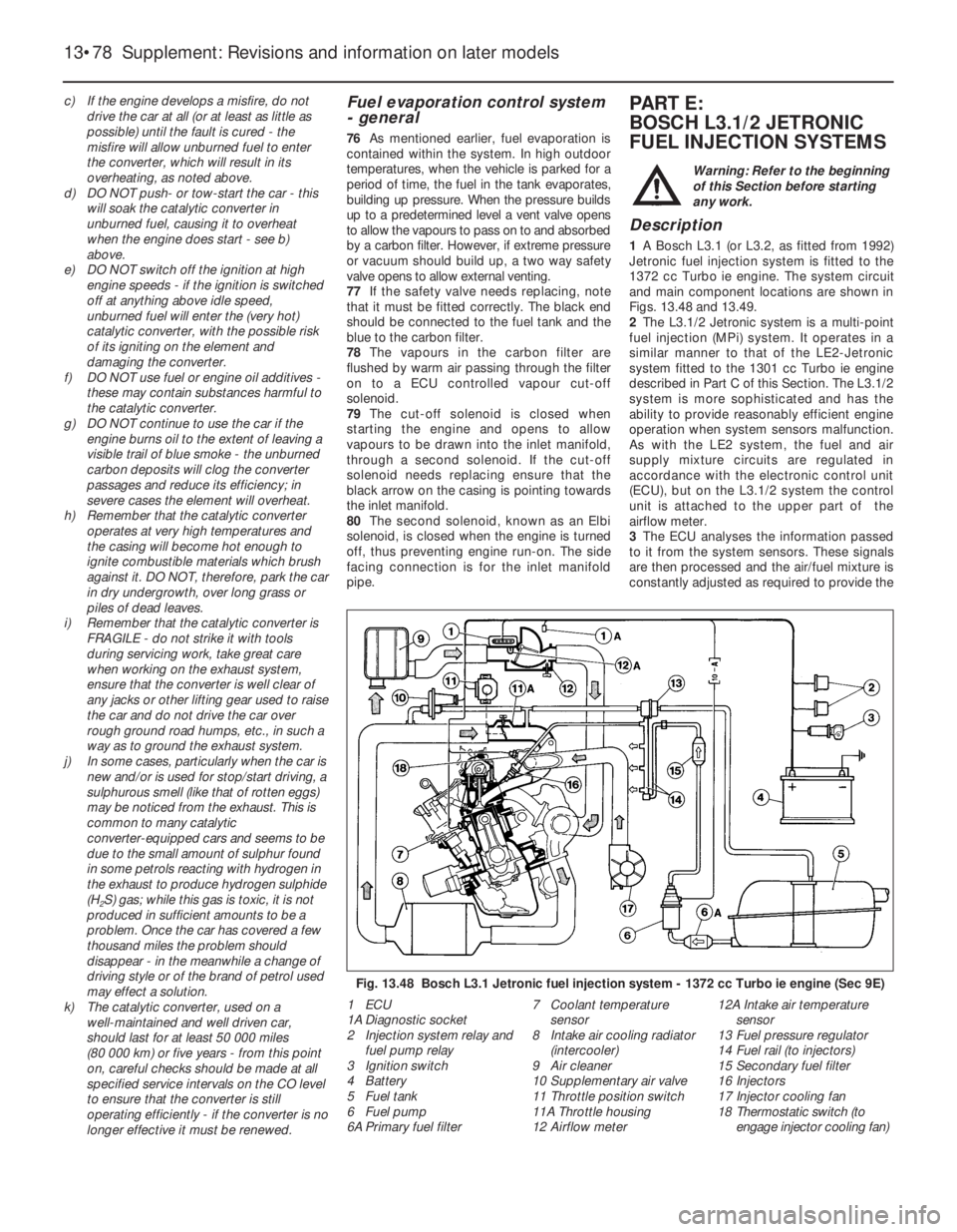
Figs. 13.48 and 13.49.
2The L3.1/2 Jetronic system is a multi-point
fuel injection (MPi) system. It operates in a
similar manner to that of the LE2-Jetronic
system fitted to the 1301 cc Turbo ie engine
described in Part C of this Section. The L3.1/2
system is more sophisticated and has the
ability to provide reasonably efficient engine
operation when system sensors malfunction.
As with the LE2 system, the fuel and air
supply mixture circuits are regulated in
accordance with the electronic control unit
(ECU), but on the L3.1/2 system the control
unit is attached to the upper part of the
airflow meter.
3The ECU analyses the information passed
to it from the system sensors. These signals
are then processed and the air/fuel mixture is
constantly adjusted as required to provide the
13•78 Supplement: Revisions and information on later models
Fig. 13.48 Bosch L3.1 Jetronic fuel injection system - 1372 cc Turbo ie engine (Sec 9E)
1 ECU
1A Diagnostic socket
2 Injection system relay and
fuel pump relay
3 Ignition switch
4 Battery
5 Fuel tank
6 Fuel pump
6A Primary fuel filter7 Coolant temperature
sensor
8 Intake air cooling radiator
(intercooler)
9 Air cleaner
10 Supplementary air valve
11 Throttle position switch
11A Throttle housing
12 Airflow meter12A Intake air temperature
sensor
13 Fuel pressure regulator
14 Fuel rail (to injectors)
15 Secondary fuel filter
16 Injectors
17 Injector cooling fan
18 Thermostatic switch (to
engage injector cooling fan)
Page 204 of 303
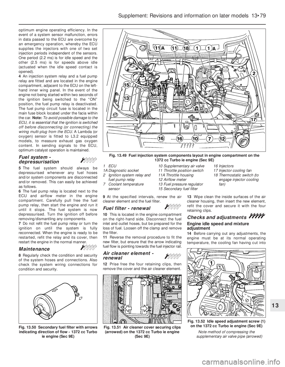
optimum engine operating efficiency. In the
event of a system sensor malfunction, errors
in data passed to the ECU are overcome by
an emergency operation, whereby the ECU
supplies the injectors with one of two set
injection periods independent of the sensors.
One period (2.2 ms) is for idle speed and the
other (2.5 ms) is for speeds above idle
(actuated when the idle speed contact is
opened).
4An injection system relay and a fuel pump
relay are fitted and are located in the engine
compartment, adjacent to the ECU on the left-
hand inner wing panel. In the event of the
engine not being started within two seconds of
the ignition being switched to the “ON”
position, the fuel pump relay is deactivated.
The fuel pump circuit fuse is located in the
main fuse block located under the facia within
the car. Note: To avoid possible damage to the
ECU, it is essential that the ignition is switched
off before disconnecting (or connecting) the
wiring multi-plug from the ECU.A Lambda (or
oxygen) sensor is fitted to L3.2 equipped
models, to measure exhaust gas oxygen
content. In sending signals to the ECU,
optimum catalyst operation is maintained.
Fuel system -
depressurisationÁ
5The fuel system should always be
depressurised whenever any fuel hoses
and/or system components are disconnected
and/or removed. This can easily be achieved
as follows.
6The fuel pump relay is located next to the
ECU and airflow meter in the engine
compartment. Carefully pull free the fuel
pump relay, then start the engine and run it
until it stops. The fuel system is now
depressurised. Turn the ignition off before
removing/dismantling any components.
7Do not refit the fuel pump relay or turn the
ignition on until the system is fully
reconnected. When the engine is ready to be
restarted, refit the relay and its cover, then
restart the engine in the normal manner.
MaintenanceÁ
8Regularly check the condition and security
of the system hoses and connections. Also
check the system wiring connections for
condition and security.9At the specified intervals, renew the air
cleaner element and the fuel filter.
Fuel filter - renewalÁ
10This is located in the engine compartment
on the right-hand side. Disconnect the fuel
inlet and outlet hoses, but be prepared for the
loss of fuel. Loosen off the clamp and remove
the filter.
11Reverse the removal procedure to fit the
new filter, but ensure that the arrow indicating
fuel flow is pointing towards the fuel injector rail.
Air cleaner element -
renewalÁ
12Prise free the four retaining clips, then
remove the cover and the air cleaner element.13Wipe clean the inside surfaces of the air
cleaner housing, then insert the new element,
refit the cover and secure it with the four
retaining clips.
Checks and adjustments°
Engine idle speed and mixture
adjustment
14Before carrying out any adjustments, the
engine must be at its normal operating
temperature, the cooling fan having cut into
Supplement: Revisions and information on later models 13•79
Fig. 13.49 Fuel injection system components layout in engine compartment on the
1372 cc Turbo ie engine (Sec 9E)
1 ECU
1A Diagnostic socket
2 Ignition system relay and
fuel pump relay
7 Coolant temperature
sensor10 Supplementary air valve
11 Throttle position switch
11A Throttle housing
12 Airflow meter
13 Fuel pressure regulator
15 Secondary fuel filter16 Injectors
17 Injector cooling fan
18 Thermostatic switch (to
engage injector cooling
fan)
Fig. 13.52 Idle speed adjustment screw (1)
on the 1372 cc Turbo ie engine (Sec 9E)
Note method of compressing the
supplementary air valve pipe (arrowed)
Fig. 13.51 Air cleaner cover securing clips
(arrowed) on the 1372 cc Turbo ie engine
(Sec 9E)Fig. 13.50 Secondary fuel filter with arrows
indicating direction of flow - 1372 cc Turbo
ie engine (Sec 9E)
13
Page 240 of 303
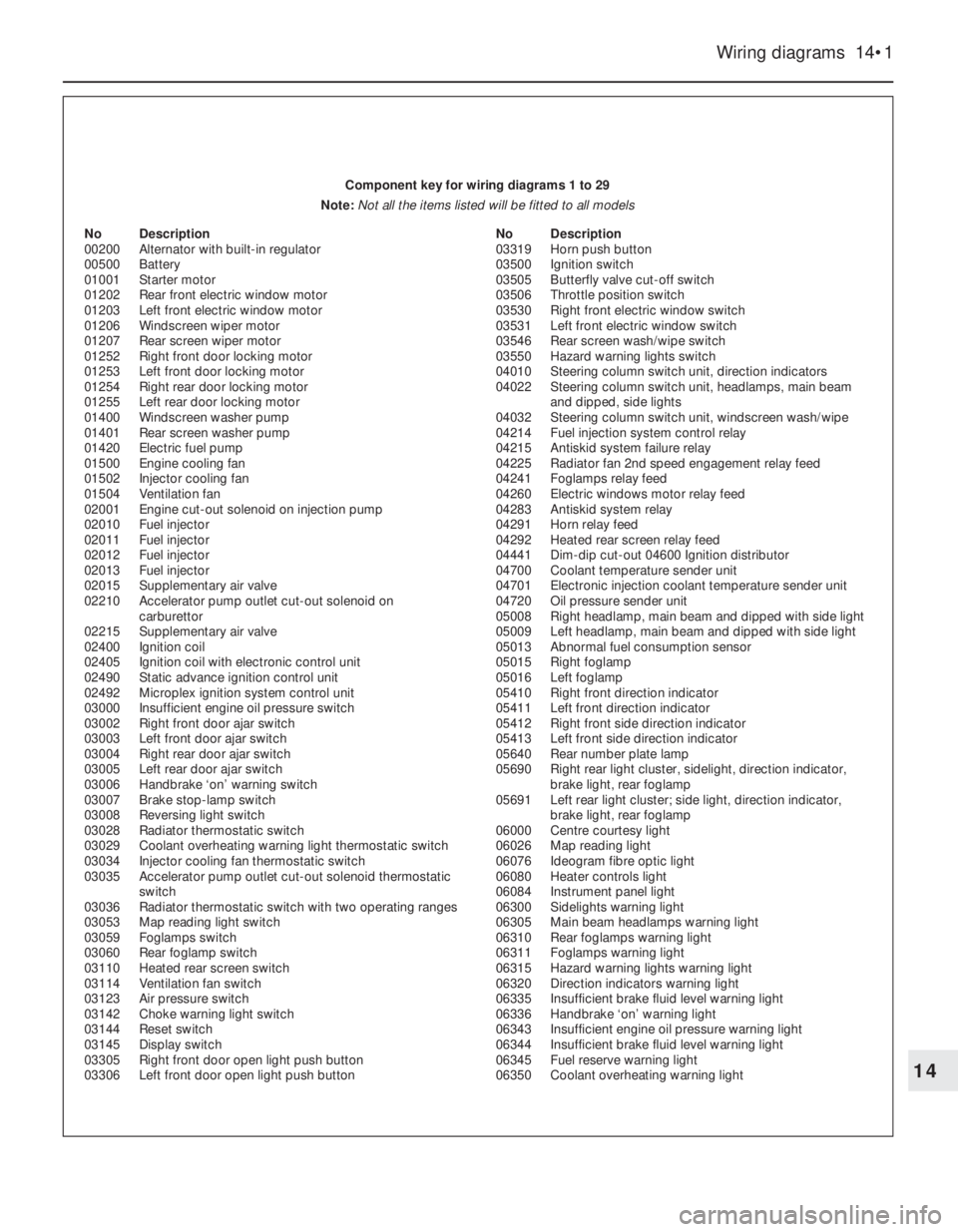
Wiring diagrams 14•1
14
Component key for wiring diagrams 1 to 29
Note: Not all the items listed will be fitted to all models
No Description
00200 Alternator with built-in regulator
00500 Battery
01001 Starter motor
01202 Rear front electric window motor
01203 Left front electric window motor
01206 Windscreen wiper motor
01207 Rear screen wiper motor
01252 Right front door locking motor
01253 Left front door locking motor
01254 Right rear door locking motor
01255 Left rear door locking motor
01400 Windscreen washer pump
01401 Rear screen washer pump
01420 Electric fuel pump
01500 Engine cooling fan
01502 Injector cooling fan
01504 Ventilation fan
02001 Engine cut-out solenoid on injection pump
02010 Fuel injector
02011 Fuel injector
02012 Fuel injector
02013 Fuel injector
02015 Supplementary air valve
02210 Accelerator pump outlet cut-out solenoid on
carburettor
02215 Supplementary air valve
02400 Ignition coil
02405 Ignition coil with electronic control unit
02490 Static advance ignition control unit
02492 Microplex ignition system control unit
03000 Insufficient engine oil pressure switch
03002 Right front door ajar switch
03003 Left front door ajar switch
03004 Right rear door ajar switch
03005 Left rear door ajar switch
03006 Handbrake ‘on’ warning switch
03007 Brake stop-lamp switch
03008 Reversing light switch
03028 Radiator thermostatic switch
03029 Coolant overheating warning light thermostatic switch
03034 Injector cooling fan thermostatic switch
03035 Accelerator pump outlet cut-out solenoid thermostatic
switch
03036 Radiator thermostatic switch with two operating ranges
03053 Map reading light switch
03059 Foglamps switch
03060 Rear foglamp switch
03110 Heated rear screen switch
03114 Ventilation fan switch
03123 Air pressure switch
03142 Choke warning light switch
03144 Reset switch
03145 Display switch
03305 Right front door open light push button
03306 Left front door open light push button No Description
03319 Horn push button
03500 Ignition switch
03505 Butterfly valve cut-off switch
03506 Throttle position switch
03530 Right front electric window switch
03531 Left front electric window switch
03546 Rear screen wash/wipe switch
03550 Hazard warning lights switch
04010 Steering column switch unit, direction indicators
04022 Steering column switch unit, headlamps, main beam
and dipped, side lights
04032 Steering column switch unit, windscreen wash/wipe
04214 Fuel injection system control relay
04215 Antiskid system failure relay
04225 Radiator fan 2nd speed engagement relay feed
04241 Foglamps relay feed
04260 Electric windows motor relay feed
04283 Antiskid system relay
04291 Horn relay feed
04292 Heated rear screen relay feed
04441 Dim-dip cut-out 04600 Ignition distributor
04700 Coolant temperature sender unit
04701 Electronic injection coolant temperature sender unit
04720 Oil pressure sender unit
05008 Right headlamp, main beam and dipped with side light
05009 Left headlamp, main beam and dipped with side light
05013 Abnormal fuel consumption sensor
05015 Right foglamp
05016 Left foglamp
05410 Right front direction indicator
05411 Left front direction indicator
05412 Right front side direction indicator
05413 Left front side direction indicator
05640 Rear number plate lamp
05690 Right rear light cluster, sidelight, direction indicator,
brake light, rear foglamp
05691 Left rear light cluster; side light, direction indicator,
brake light, rear foglamp
06000 Centre courtesy light
06026 Map reading light
06076 Ideogram fibre optic light
06080 Heater controls light
06084 Instrument panel light
06300 Sidelights warning light
06305 Main beam headlamps warning light
06310 Rear foglamps warning light
06311 Foglamps warning light
06315 Hazard warning lights warning light
06320 Direction indicators warning light
06335 Insufficient brake fluid level warning light
06336 Handbrake ‘on’ warning light
06343 Insufficient engine oil pressure warning light
06344 Insufficient brake fluid level warning light
06345 Fuel reserve warning light
06350 Coolant overheating warning light