ABS FIAT UNO 1983 Service Repair Manual
[x] Cancel search | Manufacturer: FIAT, Model Year: 1983, Model line: UNO, Model: FIAT UNO 1983Pages: 303, PDF Size: 10.36 MB
Page 34 of 303
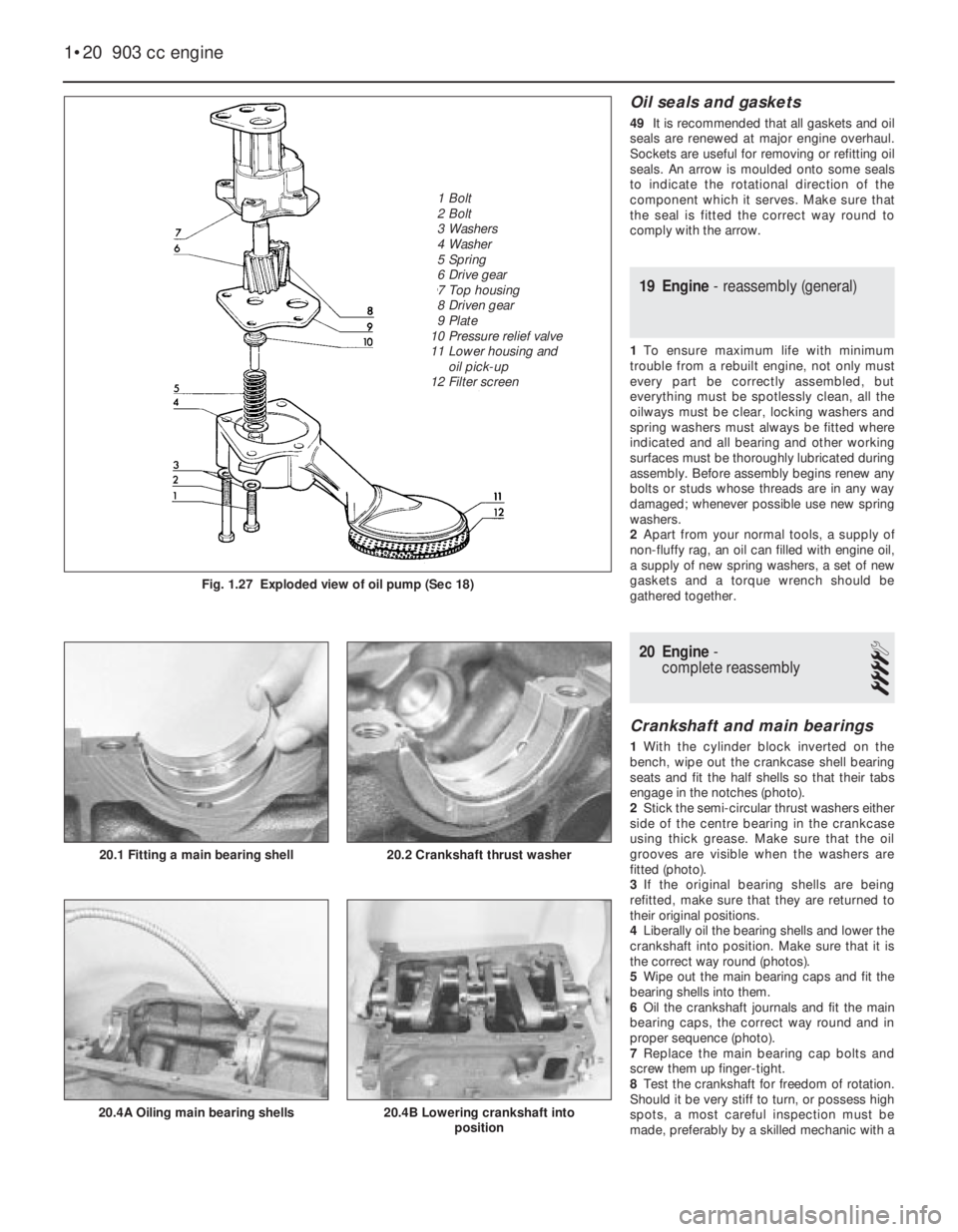
Oil seals and gaskets
49It is recommended that all gaskets and oil
seals are renewed at major engine overhaul.
Sockets are useful for removing or refitting oil
seals. An arrow is moulded onto some seals
to indicate the rotational direction of the
component which it serves. Make sure that
the seal is fitted the correct way round to
comply with the arrow.
19 Engine- reassembly (general)
1To ensure maximum life with minimum
trouble from a rebuilt engine, not only must
every part be correctly assembled, but
everything must be spotlessly clean, all the
oilways must be clear, locking washers and
spring washers must always be fitted where
indicated and all bearing and other working
surfaces must be thoroughly lubricated during
assembly. Before assembly begins renew any
bolts or studs whose threads are in any way
damaged; whenever possible use new spring
washers.
2Apart from your normal tools, a supply of
non-fluffy rag, an oil can filled with engine oil,
a supply of new spring washers, a set of new
gaskets and a torque wrench should be
gathered together.
20 Engine-
complete reassembly
4
Crankshaft and main bearings
1With the cylinder block inverted on the
bench, wipe out the crankcase shell bearing
seats and fit the half shells so that their tabs
engage in the notches (photo).
2Stick the semi-circular thrust washers either
side of the centre bearing in the crankcase
using thick grease. Make sure that the oil
grooves are visible when the washers are
fitted (photo).
3If the original bearing shells are being
refitted, make sure that they are returned to
their original positions.
4Liberally oil the bearing shells and lower the
crankshaft into position. Make sure that it is
the correct way round (photos).
5Wipe out the main bearing caps and fit the
bearing shells into them.
6Oil the crankshaft journals and fit the main
bearing caps, the correct way round and in
proper sequence (photo).
7Replace the main bearing cap bolts and
screw them up finger-tight.
8Test the crankshaft for freedom of rotation.
Should it be very stiff to turn, or possess high
spots, a most careful inspection must be
made, preferably by a skilled mechanic with a
1•20 903 cc engine
20.4B Lowering crankshaft into
position20.4A Oiling main bearing shells
20.2 Crankshaft thrust washer20.1 Fitting a main bearing shell
Fig. 1.27 Exploded view of oil pump (Sec 18)
1 Bolt
2 Bolt
3 Washers
4 Washer
5 Spring
6 Drive gear
7 Top housing
8 Driven gear
9 Plate
10 Pressure relief valve
11 Lower housing and
oil pick-up
12 Filter screen
Page 71 of 303
6On 1116 cc and 1301 cc models, the
exhaust system is of dual downpipe, two
silencer, two section type.
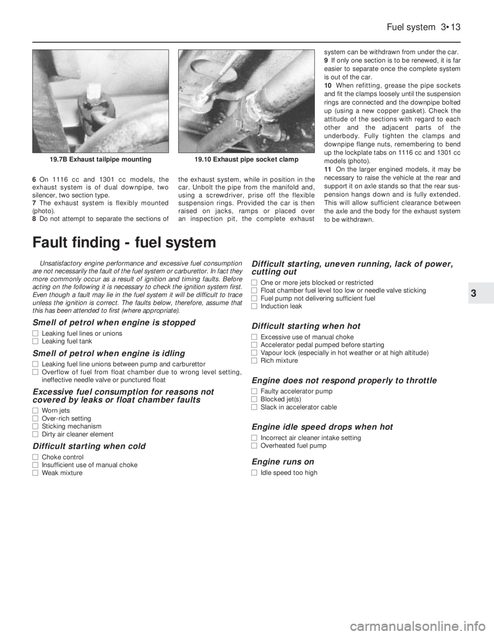
7The exhaust system is flexibly mounted
(photo).
8Do not attempt to separate the sections ofthe exhaust system, while in position in the
car. Unbolt the pipe from the manifold and,
using a screwdriver, prise off the flexible
suspension rings. Provided the car is then
raised on jacks, ramps or placed over
an inspection pit, the complete exhaust system can be withdrawn from under the car.
9If only one section is to be renewed, it is far
easier to separate once the complete system
is out of the car.
10When refitting, grease the pipe sockets
and fit the clamps loosely until the suspension
rings are connected and the downpipe bolted
up (using a new copper gasket). Check the
attitude of the sections with regard to each
other and the adjacent parts of the
underbody. Fully tighten the clamps and
downpipe flange nuts, remembering to bend
up the lockplate tabs on 1116 cc and 1301 cc
models (photo).
11On the larger engined models, it may be
necessary to raise the vehicle at the rear and
support it on axle stands so that the rear sus-
pension hangs down and is fully extended.
This will allow sufficient clearance between
the axle and the body for the exhaust system
to be withdrawn.
Fuel system 3•13
3
19.10 Exhaust pipe socket clamp19.7B Exhaust tailpipe mounting
Fault finding - fuel system
Unsatisfactory engine performance and excessive fuel consumption
are not necessarily the fault of the fuel system or carburettor. In fact they
more commonly occur as a result of ignition and timing faults. Before
acting on the following it is necessary to check the ignition system first.
Even though a fault may lie in the fuel system it will be difficult to trace
unless the ignition is correct. The faults below, therefore, assume that
this has been attended to first (where appropriate).
Smell of petrol when engine is stopped
m mLeaking fuel lines or unions
m mLeaking fuel tank
Smell of petrol when engine is idling
m
mLeaking fuel line unions between pump and carburettor
m mOverflow of fuel from float chamber due to wrong level setting,
ineffective needle valve or punctured float
Excessive fuel consumption for reasons not
covered by leaks or float chamber faults
m mWorn jets
m mOver-rich setting
m mSticking mechanism
m mDirty air cleaner element
Difficult starting when cold
m
mChoke control
m mInsufficient use of manual choke
m mWeak mixture
Difficult starting, uneven running, lack of power,
cutting out
m mOne or more jets blocked or restricted
m mFloat chamber fuel level too low or needle valve sticking
m mFuel pump not delivering sufficient fuel
m mInduction leak
Difficult starting when hot
m
mExcessive use of manual choke
m mAccelerator pedal pumped before starting
m mVapour lock (especially in hot weather or at high altitude)
m mRich mixture
Engine does not respond properly to throttle
m
mFaulty accelerator pump
m mBlocked jet(s)
m mSlack in accelerator cable
Engine idle speed drops when hot
m
mIncorrect air cleaner intake setting
m mOverheated fuel pump
Engine runs on
m
mIdle speed too high
Page 79 of 303
this type is used and the engine is in good
condition, the spark plugs should not need
attention between scheduled replacement
intervals. Spark plug cleaning is rarely
necessary and should not be attempted unless
specialised equipment is available as damage
can easily be caused to the firing ends.
2At the specified intervals, the plugs should
be renewed. The condition of the spark plug
will also tell much about the overall condition
of the engine.
3If the insulator nose of the spark plug is
clean and white, with no deposits, this is
indicative of a weak mixture, or too hot a plug.
(A hot plug transfers heat away from the
electrode slowly - a cold plug transfers it away
quickly.)
4If the tip of the insulator nose is covered
with sooty black deposits, then this is
indicative that the mixture is too rich. Should
the plug be black and oily, then it is likely that
the engine is fairly worn, as well as the mixture
being too rich.
5The spark plug gap is of considerable
importance, as, if it is too large or too small
the size of the spark and its efficiency will be
seriously impaired. The spark plug gap should
be set to the gap shown in the Specifications
for the best results.
6To set it, measure the gap with a feeler
gauge, and then bend open, or close, the
outer plug electrode until the correct gap is
achieved. The centre electrode should never
be bent as this may crack the insulation and
cause plug failure, if nothing worse.
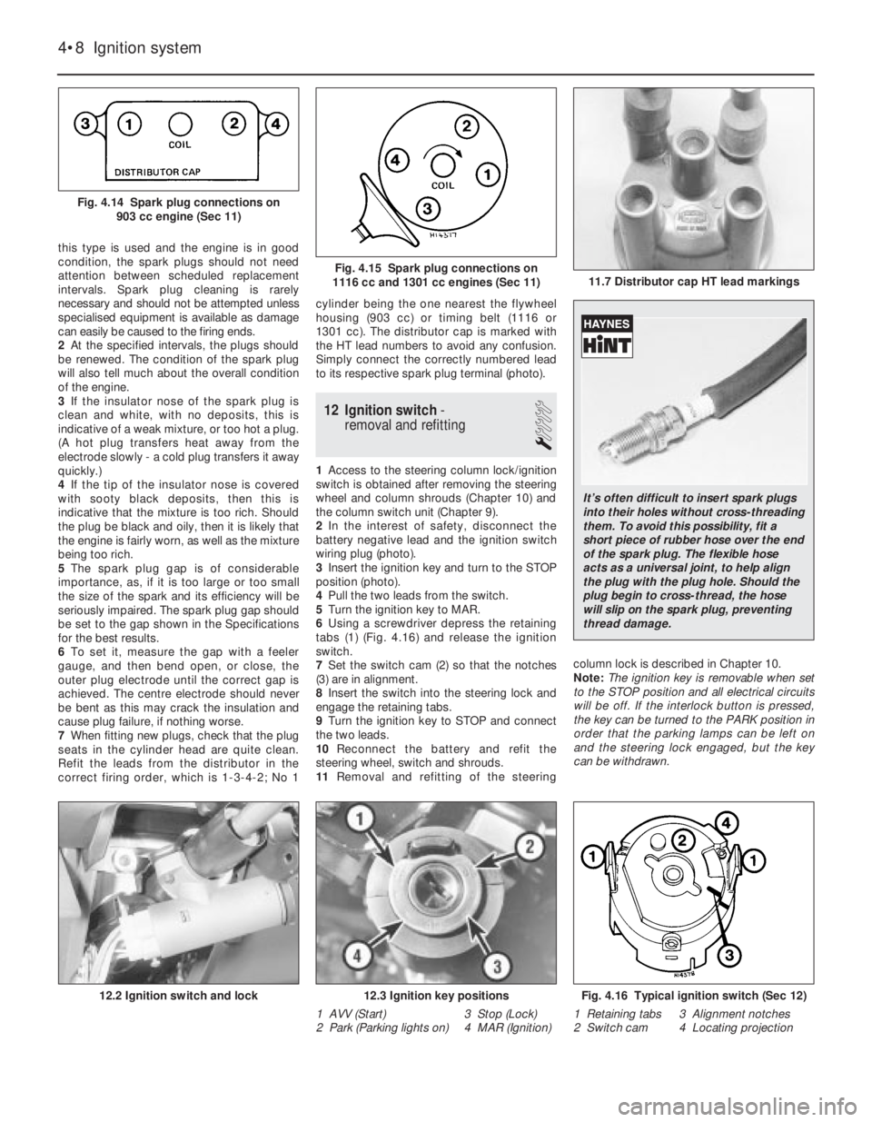
7When fitting new plugs, check that the plug
seats in the cylinder head are quite clean.
Refit the leads from the distributor in the
correct firing order, which is 1-3-4-2; No 1cylinder being the one nearest the flywheel
housing (903 cc) or timing belt (1116 or
1301 cc). The distributor cap is marked with
the HT lead numbers to avoid any confusion.
Simply connect the correctly numbered lead
to its respective spark plug terminal (photo).
12 Ignition switch-
removal and refitting
1
1Access to the steering column lock/ignition
switch is obtained after removing the steering
wheel and column shrouds (Chapter 10) and
the column switch unit (Chapter 9).
2In the interest of safety, disconnect the
battery negative lead and the ignition switch
wiring plug (photo).
3Insert the ignition key and turn to the STOP
position (photo).
4Pull the two leads from the switch.
5Turn the ignition key to MAR.
6Using a screwdriver depress the retaining
tabs (1) (Fig. 4.16) and release the ignition
switch.
7Set the switch cam (2) so that the notches
(3) are in alignment.
8Insert the switch into the steering lock and
engage the retaining tabs.
9Turn the ignition key to STOP and connect
the two leads.
10Reconnect the battery and refit the
steering wheel, switch and shrouds.
11Removal and refitting of the steeringcolumn lock is described in Chapter 10.
Note: The ignition key is removable when set
to the STOP position and all electrical circuits
will be off. If the interlock button is pressed,
the key can be turned to the PARK position in
order that the parking lamps can be left on
and the steering lock engaged, but the key
can be withdrawn.
4•8 Ignition system
Fig. 4.16 Typical ignition switch (Sec 12)
1 Retaining tabs 3 Alignment notches
2 Switch cam 4 Locating projection12.3 Ignition key positions
1 AVV (Start) 3 Stop (Lock)
2 Park (Parking lights on) 4 MAR (Ignition)12.2 Ignition switch and lock
11.7 Distributor cap HT lead markingsFig. 4.15 Spark plug connections on
1116 cc and 1301 cc engines (Sec 11)
Fig. 4.14 Spark plug connections on
903 cc engine (Sec 11)
It’s often difficult to insert spark plugs
into their holes without cross-threading
them. To avoid this possibility, fit a
short piece of rubber hose over the end
of the spark plug. The flexible hose
acts as a universal joint, to help align
the plug with the plug hole. Should the
plug begin to cross-thread, the hose
will slip on the spark plug, preventing
thread damage.
Page 84 of 303
assembly and the flexible pipe, particularly the
fixing bracket and union at the car end of the
flexible pipe.
3Have ready a container suitable to catch
the brake fluid, and sheets of clean
newspaper on which to put parts.
4Take out the spring clips and locking
blocks, and take the caliper off the support
bracket.
5Disconnect the hydraulic flexible pipe at the
under wing support bracket and cap both
pipe ends. It may help to prevent loss of fluid
if the vent in the reservoir cap is sealed with
adhesive tape, to create a vacuum.
6Remove the caliper to the bench or other
work surface, and clean it thoroughly with
hydraulic fluid or methylated spirit.
7Depress the piston until the dust excluding
boot can be removed.
8Now apply air pressure to the flexible hose
and eject the piston. Quite a low pressure is
required for this, such as can be generated
with a hand or foot operated pump.
9Pick out the piston seal from its groove in
the cylinder. Use a sharp probe, but take care
to avoid scratching the cylinder bore.
10Examine the surface of the piston and
cylinder bore. If either is corroded, scored or
shows metal-to-metal rubbed areas, the
complete assembly should be renewed.
11If the components are in good condition,
discard the oil seals, clean the piston and
cylinder and fit the new seal for the piston.
This is included in the repair kit. Use the
fingers only to manipulate it into its groove.
12Lubricate the piston with clean hydraulic
fluid and insert it partially into the cylinder.
13Fit the new dust excluding boot to its
projecting end, push the piston fully into the
cylinder and engage the dust excluder with
the rim of the cylinder.
14Refit the caliper, reconnect the flexible
hose, then bleed the front hydraulic circuit
(refer to Section 12).
6 Brake disc- inspection,
renovation or renewal
2
1Whenever the front disc pads are being
checked for wear, take the opportunity to
inspect the discs for deep scoring or
grooving. After a high mileage the disc may
become reduced in thickness away from the
extreme outer edge of the disc. lf this wear is
rapid, it is possible that the friction pads are of
too hard a type.
2If the disc has evidence of many tiny cracks,
these may be caused by overheating due to a
seized caliper piston in the “applied” position.
3The foregoing conditions may be corrected
by regrinding the disc provided that the
thickness of the disc is not reduced below
that specified by such action. Alternatively, fit
a new disc.
4To remove a disc, take off the caliper andpads as described in Sections 3 and 5. Tie the
caliper up, out of the way.
5Knock back the tabs of the lockplates and
unbolt the caliper support bracket from the
hub carrier.
6Unscrew and remove the two bolts which
hold the disc assembly to the hub. One of
these bolts is for wheel locating purposes.
7Pull the disc from the hub.
8Refitting is a reversal of the removal
process. If the disc has excessive run-out,
repositioning it in relation to the hub may
bring it within tolerance by cancelling out the
run-out characteristics in the hub and disc,
once the most suitable fitted position has
been found.
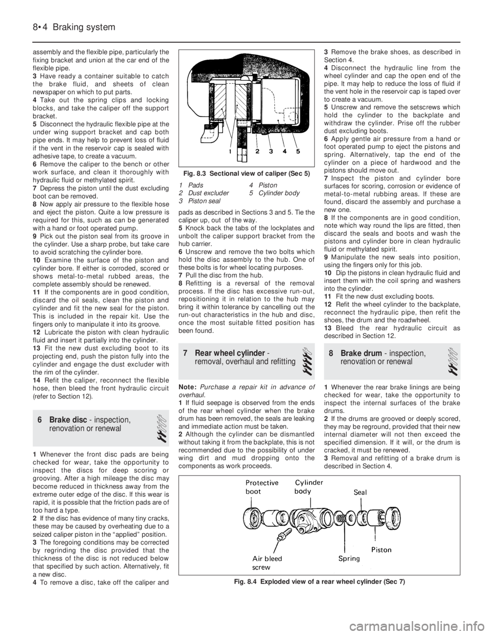
7 Rear wheel cylinder-
removal, overhaul and refitting
4
Note: Purchase a repair kit in advance of
overhaul.
1If fluid seepage is observed from the ends
of the rear wheel cylinder when the brake
drum has been removed, the seals are leaking
and immediate action must be taken.
2Although the cylinder can be dismantled
without taking it from the backplate, this is not
recommended due to the possibility of under
wing dirt and mud dropping onto the
components as work proceeds. 3Remove the brake shoes, as described in
Section 4.
4Disconnect the hydraulic line from the
wheel cylinder and cap the open end of the
pipe. lt may help to reduce the loss of fluid if
the vent hole in the reservoir cap is taped over
to create a vacuum.
5Unscrew and remove the setscrews which
hold the cylinder to the backplate and
withdraw the cylinder. Prise off the rubber
dust excluding boots.
6Apply gentle air pressure from a hand or
foot operated pump to eject the pistons and
spring. Alternatively, tap the end of the
cylinder on a piece of hardwood and the
pistons should move out.
7Inspect the piston and cylinder bore
surfaces for scoring, corrosion or evidence of
metal-to-metal rubbing areas. lf these are
found, discard the assembly and purchase a
new one.
8If the components are in good condition,
note which way round the lips are fitted, then
discard the seals and boots and wash the
pistons and cylinder bore in clean hydraulic
fluid or methylated spirit.
9Manipulate the new seals into position,
using the fingers only for this job.
10Dip the pistons in clean hydraulic fluid and
insert them with the coil spring and washers
into the cylinder.
11Fit the new dust excluding boots.
12Refit the wheel cylinder to the backplate,
reconnect the hydraulic pipe, then refit the
shoes, the drum and the roadwheel.
13Bleed the rear hydraulic circuit as
described in Section 12.
8 Brake drum- inspection,
renovation or renewal
2
1Whenever the rear brake linings are being
checked for wear, take the opportunity to
inspect the internal surfaces of the brake
drums.
2If the drums are grooved or deeply scored,
they may be reground, provided that their new
internal diameter will not then exceed the
specified dimension. If it will, or the drum is
cracked, it must be renewed.
3Removal and refitting of a brake drum is
described in Section 4.
8•4 Braking system
Fig. 8.4 Exploded view of a rear wheel cylinder (Sec 7)
1 Pads
2 Dust excluder
3 Piston seal4 Piston
5 Cylinder body
Fig. 8.3 Sectional view of caliper (Sec 5)
Page 88 of 303
20By connecting a pressurised container to
the master cylinder fluid reservoir, bleeding is
then carried out by simply opening each bleed
screw in turn and allowing the fluid to run out,
rather like turning on a tap, until no air is
visible in the expelled fluid.
21By using this method, the large reserve of
hydraulic fluid provides a safeguard against
air being drawn into the master cylinder
during bleeding which often occurs if the fluid
level in the reservoir is not maintained.
22Pressure bleeding is particularly effective
when bleeding “difficult” systems or when
bleeding the complete system at time of
routine fluid renewal.
All methods
23When bleeding is completed, check and
top up the fluid level in the master cylinder
reservoir.
24Check the feel of the brake pedal. If it
feels at all spongy, air must still be present in
the system and further bleeding is indicated.
Failure to bleed satisfactorily after a
reasonable period of the bleeding operation,
may be due to worn master cylinder seals.
25Discard brake fluid which has been
expelled. lt is almost certain to be
contaminated with moisture, air and dirt
making it unsuitable for further use. Clean
fluid should always be stored in an airtight
container as it absorbs moisture readily
(hygroscopic) which lowers its boiling point
and could affect braking performance under
severe conditions.
13 Vacuum servo unit-
description
A vacuum servo unit is fitted into the brake
hydraulic circuit on 55 and 70 models in series
with the master cylinder, to provide assistance
to the driver when the brake pedal is
depressed. This reduces the effort required by
the driver to operate the brakes under all
braking conditions.
The unit operates by vacuum obtained from
the induction manifold and comprises basically
a booster diaphragm and non-return valve. The
servo unit and hydraulic master cylinder are
connected together so that the servo unit
piston rod acts as the master cylinder pushrod.
The driver’s braking effort is transmitted
through another pushrod to the servo unit
piston and its built-in control system. The servo
unit piston does not fit tightly into the cylinder,
but has a strong diaphragm to keep its edges
in constant contact with the cylinder wall, so
assuring an air tight seal between the two
parts. The forward chamber is held under
vacuum conditions created in the inlet manifold
of the engine and, during periods when the
brake pedal is not in use, the controls open a
passage to the rear chamber so placing it
under vacuum conditions as well. When the
brake pedal is depressed, the vacuum passageto the rear chamber is cut off and the chamber
opened to atmospheric pressure. The
consequent rush of air pushes the servo piston
forward in the vacuum chamber and operates
the main pushrod to the master cylinder.
The controls are designed so that
assistance is given under all conditions and,
when the brakes are not required, vacuum in
the rear chamber is established when the
brake pedal is released. All air from the
atmosphere entering the rear chamber is
passed through a small air filter.
Under normal operating conditions, the
vacuum servo unit is very reliable and does
not require overhaul except at very high
mileages. In this case, it is far better to obtain
a service exchange unit, rather than repair the
original unit.
It is emphasised that the servo unit assists
in reducing the braking effort required at the
foot pedal and in the event of its failure, the
hydraulic braking system is in no way affected
except that the need for higher pressures will
be noticed.
14 Vacuum servo unit-
servicing and testing
1Regularly, check that the vacuum hose
which runs between the servo unit and the
inlet manifold is in good condition and is a
tight fit at both ends.
2If broken or badly clogged, renew the air
filter which is located around the brake pedal
push rod. Access to this is obtained by
disconnecting the pushrod from the
cross-shaft or pedal arm, withdrawing the
pushrod, dust excluding boot and end cap.
3If the new filter is cut diagonally from its
centre hole, future renewal can be carried out
without the need for disconnection of the
pushrod.
4If the efficiency of the servo unit is suspect,
it can be checked out in the following way.
5Run the engine, then switch off the ignition.
Depress the footbrake pedal; the distinctive
in-rush of air into the servo should be clearly
heard. It should be possible to repeat this
operation several times before the vacuum in
the system is exhausted.
6Start the engine and have an assistant
apply the footbrake pedal and hold it down.
Disconnect the vacuuum hose from the servo.
There should not be any in-rush of air into the
servo through the connecting stub. lf there is,
the servo diaphragm is probably faulty. During
this test, expect the engine to idle roughly,
unless the open end of the hose to the inlet
manifold is plugged. Reconnect the hose.
7With the engine off, depress the brake
pedal fully. Start the engine with the brake
pedal still depressed; the pedal should be felt
to go down fractionally.
8If the results of these tests are not
satisfactory, remove the unit and fit a new one
as described in the next Section.
15 Vacuum servo unit-
removal and refitting
3
1Syphon as much fluid as possible out of the
master cylinder reservolr.
2Disconnect electrical leads from the
terminals in the reservoir cap then uncouple
the rigid pipelines from the master cylinder
body. Be prepared to catch leaking fluid and
plug the open ends of the pipelines.
3The master cylinder can be unbolted now
from the servo unit, or detached later when
the complete assembly is withdrawn.
4Working inside the car, disconnect the
servo pushrod from the pedal then remove the
servo mounting nuts.
5Withdraw the servo assembly into the
engine compartment, then remove it to the
bench. lf the master cylinder is still attached,
cover the wings with protective sheeting, in
case brake fluid is spilled during removal.
6Refitting is a reversal of the removal
process, but adjust the pushrod clearance as
described in Section 9. On completion of
refitting, bleed the complete hydraulic system
as described in Section 12. Note: Where the
help of an assistant is available, the servo
pushrod need not be disconnected from the
pedal. The rod is a sliding fit in the servo and
the servo can be simply pulled off the rod.
Refitting without having disconnected the rod
from the pedal can be difficult unless the help
of an assistant is available.
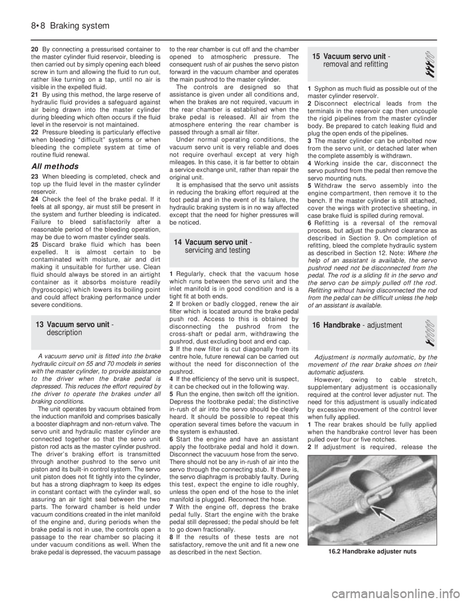
16 Handbrake- adjustment
1
Adjustment is normally automatic, by the
movement of the rear brake shoes on their
automatic adjusters.
However, owing to cable stretch,
supplementary adjustment is occasionally
required at the control lever adjuster nut. The
need for this adjustment is usually indicated
by excessive movement of the control lever
when fully applied.
1The rear brakes should be fully applied
when the handbrake control lever has been
pulled over four or five notches.
2If adjustment is required, release the
8•8 Braking system
16.2 Handbrake adjuster nuts
Page 95 of 303
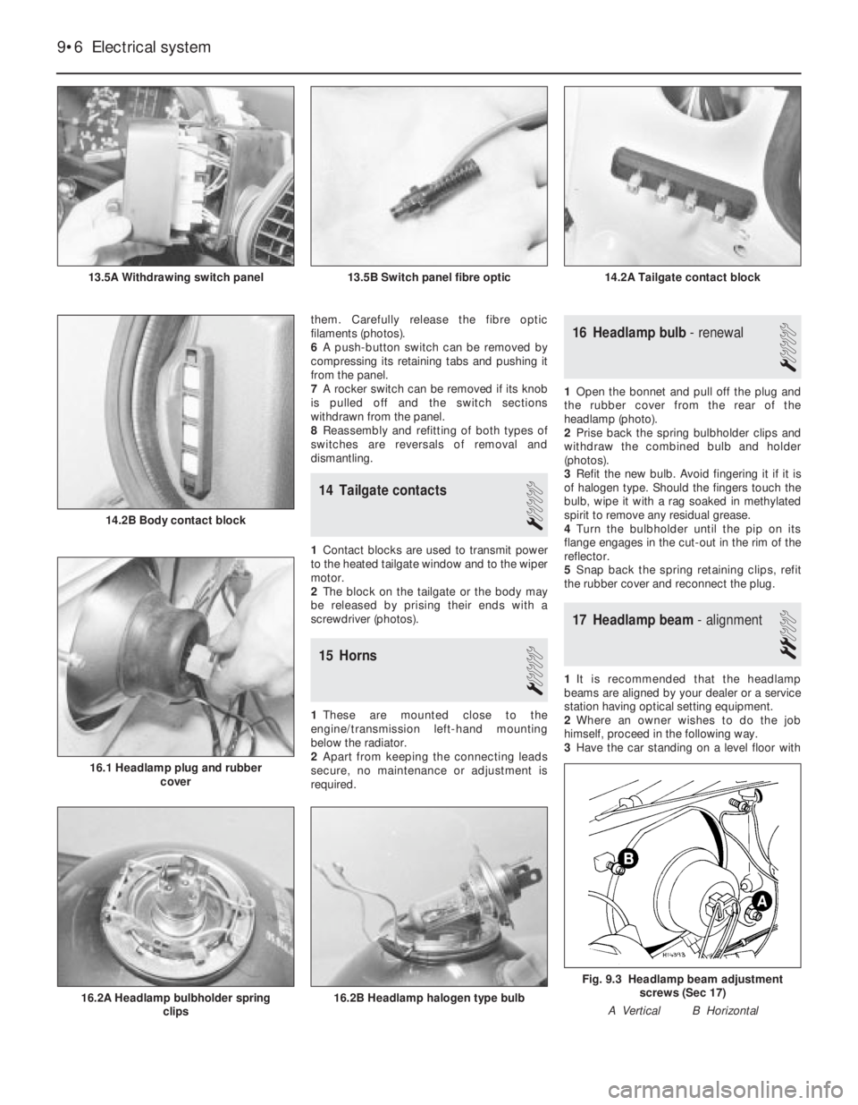
them. Carefully release the fibre optic
filaments (photos).
6A push-button switch can be removed by
compressing its retaining tabs and pushing it
from the panel.
7A rocker switch can be removed if its knob
is pulled off and the switch sections
withdrawn from the panel.
8Reassembly and refitting of both types of
switches are reversals of removal and
dismantling.
14 Tailgate contacts
1
1Contact blocks are used to transmit power
to the heated tailgate window and to the wiper
motor.
2The block on the tailgate or the body may
be released by prising their ends with a
screwdriver (photos).
15 Horns
1
1These are mounted close to the
engine/transmission left-hand mounting
below the radiator.
2Apart from keeping the connecting leads
secure, no maintenance or adjustment is
required.
16 Headlamp bulb- renewal
1
1Open the bonnet and pull off the plug and
the rubber cover from the rear of the
headlamp (photo).
2Prise back the spring bulbholder clips and
withdraw the combined bulb and holder
(photos).
3Refit the new bulb. Avoid fingering it if it is
of halogen type. Should the fingers touch the
bulb, wipe it with a rag soaked in methylated
spirit to remove any residual grease.
4Turn the bulbholder until the pip on its
flange engages in the cut-out in the rim of the
reflector.
5Snap back the spring retaining clips, refit
the rubber cover and reconnect the plug.
17 Headlamp beam- alignment
2
1It is recommended that the headlamp
beams are aligned by your dealer or a service
station having optical setting equipment.
2Where an owner wishes to do the job
himself, proceed in the following way.
3Have the car standing on a level floor with
9•6 Electrical system
Fig. 9.3 Headlamp beam adjustment
screws (Sec 17)
A Vertical B Horizontal
16.2B Headlamp halogen type bulb16.2A Headlamp bulbholder spring
clips
14.2B Body contact block
16.1 Headlamp plug and rubber
cover
14.2A Tailgate contact block13.5B Switch panel fibre optic13.5A Withdrawing switch panel
Page 96 of 303
the tyres correctly inflated and square to a
wall, at a distance of 10.0 m (32.8 ft) from it.
4Mark the wall to correspond with the
centres of the headlamps.
5Switch to dipped beams when the brightest
parts of the light pattern should be below the
marks on the wall by an amount equal to one
tenth of the distance between the floor and
the mark on the wall.
6Adjust the beams as necessary by turning
the adjuster screws (A) vertical or (B) hori-
zontal, which are located at the rear of the
headlamp.
18 Headlamp-
removal and refitting
1
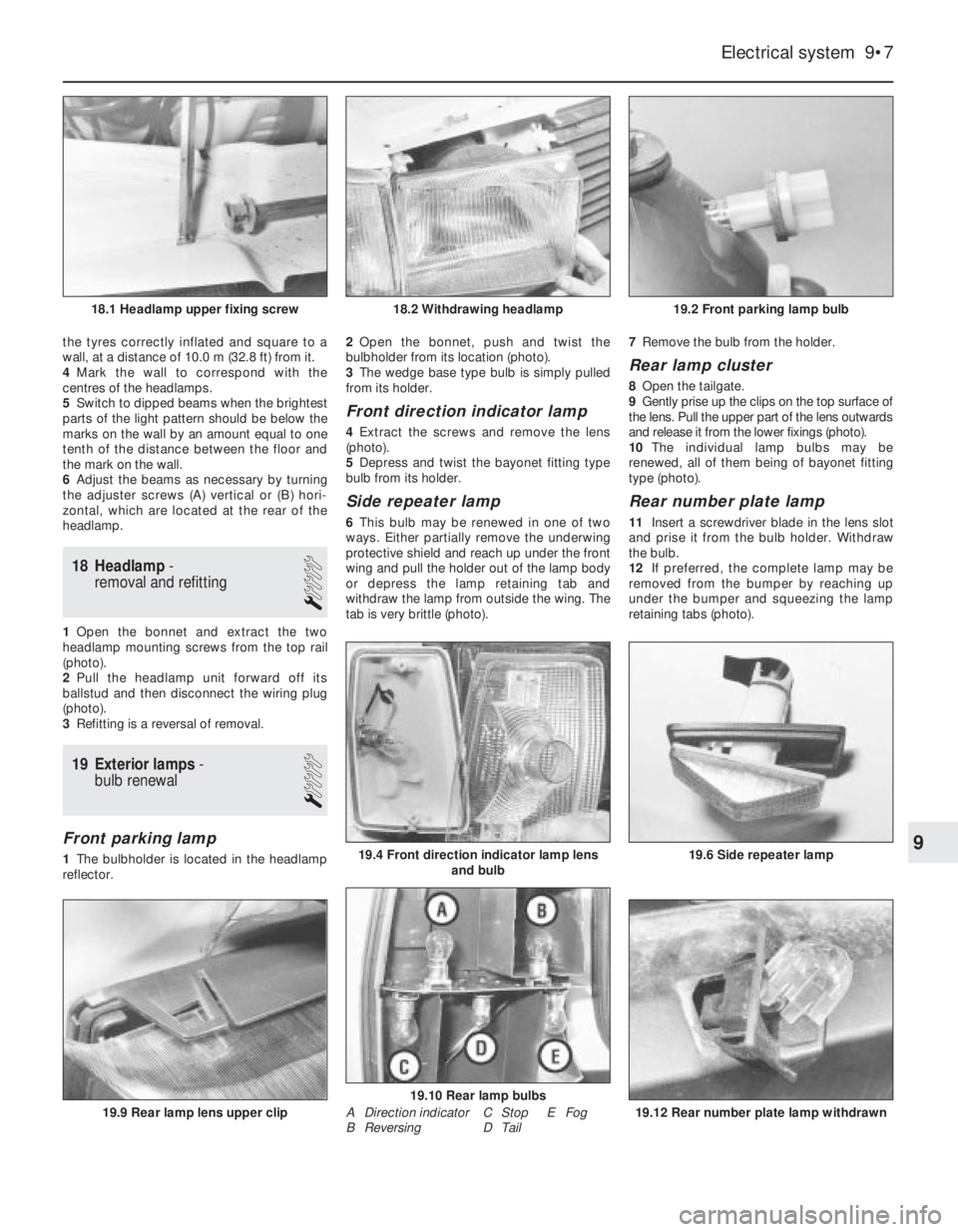
1Open the bonnet and extract the two
headlamp mounting screws from the top rail
(photo).
2Pull the headlamp unit forward off its
ballstud and then disconnect the wiring plug
(photo).
3Refitting is a reversal of removal.
19 Exterior lamps-
bulb renewal
1
Front parking lamp
1The bulbholder is located in the headlamp
reflector. 2Open the bonnet, push and twist the
bulbholder from its location (photo).
3The wedge base type bulb is simply pulled
from its holder.
Front direction indicator lamp
4Extract the screws and remove the lens
(photo).
5Depress and twist the bayonet fitting type
bulb from its holder.
Side repeater lamp
6This bulb may be renewed in one of two
ways. Either partially remove the underwing
protective shield and reach up under the front
wing and pull the holder out of the lamp body
or depress the lamp retaining tab and
withdraw the lamp from outside the wing. The
tab is very brittle (photo). 7Remove the bulb from the holder.
Rear lamp cluster
8Open the tailgate.
9Gently prise up the clips on the top surface of
the lens. Pull the upper part of the lens outwards
and release it from the lower fixings (photo).
10The individual lamp bulbs may be
renewed, all of them being of bayonet fitting
type (photo).
Rear number plate lamp
11Insert a screwdriver blade in the lens slot
and prise it from the bulb holder. Withdraw
the bulb.
12If preferred, the complete lamp may be
removed from the bumper by reaching up
under the bumper and squeezing the lamp
retaining tabs (photo).
Electrical system 9•7
19.2 Front parking lamp bulb18.2 Withdrawing headlamp18.1 Headlamp upper fixing screw
19.12 Rear number plate lamp withdrawn
19.10 Rear lamp bulbs
19.6 Side repeater lamp19.4 Front direction indicator lamp lens
and bulb
19.9 Rear lamp lens upper clip
9
A Direction indicator
B ReversingC Stop E Fog
D Tail
Page 108 of 303
11
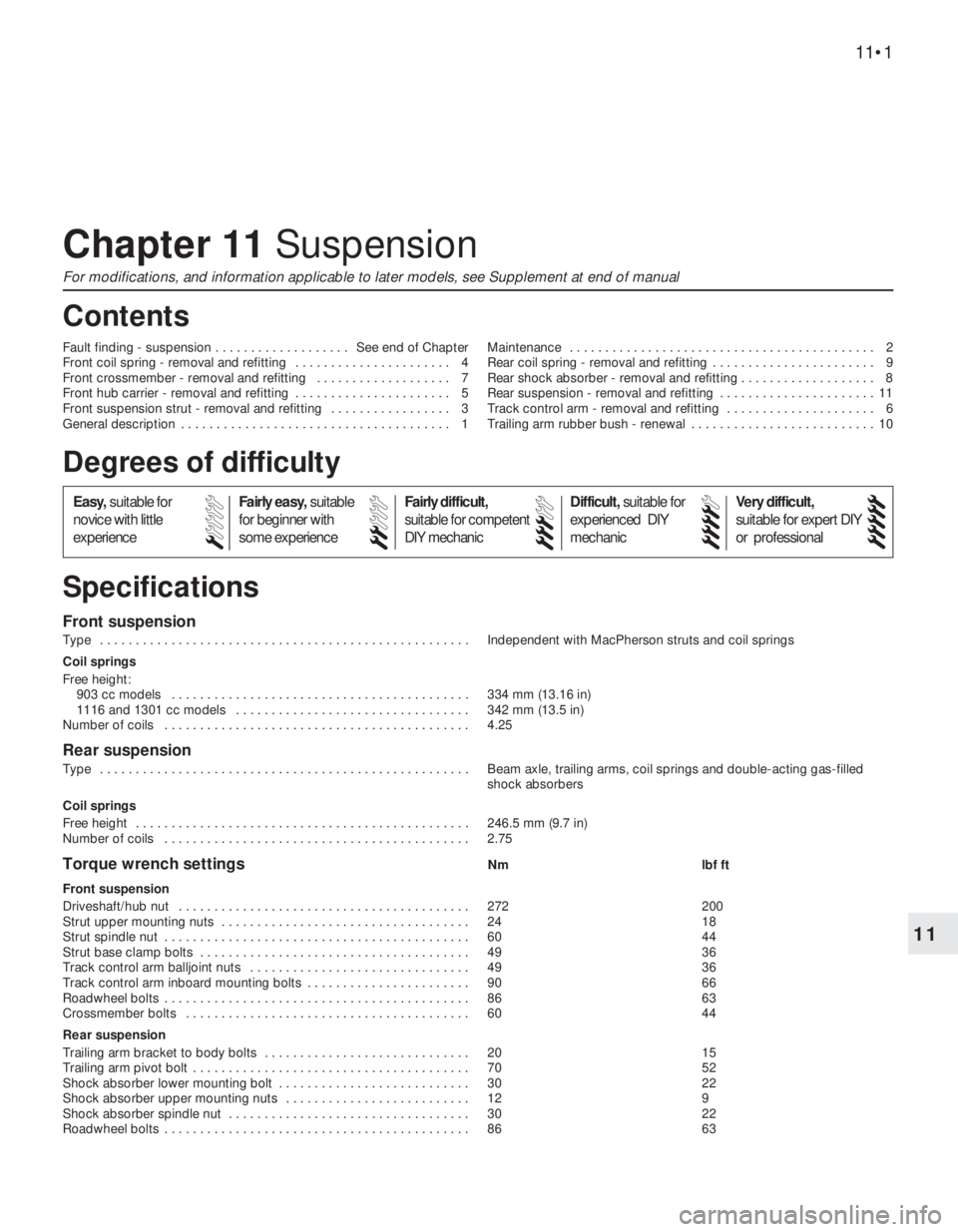
Front suspension
Type . . . . . . . . . . . . . . . . . . . . . . . . . . . . . . . . . . . . . . . . . . . . . . . . . . . . Independent with MacPherson struts and coil springs
Coil springs
Free height:
903 cc models . . . . . . . . . . . . . . . . . . . . . . . . . . . . . . . . . . . . . . . . . . 334 mm (13.16 in)
1116 and 1301 cc models . . . . . . . . . . . . . . . . . . . . . . . . . . . . . . . . . 342 mm (13.5 in)
Number of coils . . . . . . . . . . . . . . . . . . . . . . . . . . . . . . . . . . . . . . . . . . . 4.25
Rear suspension
Type . . . . . . . . . . . . . . . . . . . . . . . . . . . . . . . . . . . . . . . . . . . . . . . . . . . . Beam axle, trailing arms, coil springs and double-acting gas-filled
shock absorbers
Coil springs
Free height . . . . . . . . . . . . . . . . . . . . . . . . . . . . . . . . . . . . . . . . . . . . . . . 246.5 mm (9.7 in)
Number of coils . . . . . . . . . . . . . . . . . . . . . . . . . . . . . . . . . . . . . . . . . . . 2.75
Torque wrench settingsNm lbf ft
Front suspension
Driveshaft/hub nut . . . . . . . . . . . . . . . . . . . . . . . . . . . . . . . . . . . . . . . . . 272 200
Strut upper mounting nuts . . . . . . . . . . . . . . . . . . . . . . . . . . . . . . . . . . . 24 18
Strut spindle nut . . . . . . . . . . . . . . . . . . . . . . . . . . . . . . . . . . . . . . . . . . . 60 44
Strut base clamp bolts . . . . . . . . . . . . . . . . . . . . . . . . . . . . . . . . . . . . . . 49 36
Track control arm balljoint nuts . . . . . . . . . . . . . . . . . . . . . . . . . . . . . . . 49 36
Track control arm inboard mounting bolts . . . . . . . . . . . . . . . . . . . . . . . 90 66
Roadwheel bolts . . . . . . . . . . . . . . . . . . . . . . . . . . . . . . . . . . . . . . . . . . . 86 63
Crossmember bolts . . . . . . . . . . . . . . . . . . . . . . . . . . . . . . . . . . . . . . . . 60 44
Rear suspension
Trailing arm bracket to body bolts . . . . . . . . . . . . . . . . . . . . . . . . . . . . . 20 15
Trailing arm pivot bolt . . . . . . . . . . . . . . . . . . . . . . . . . . . . . . . . . . . . . . . 70 52
Shock absorber lower mounting bolt . . . . . . . . . . . . . . . . . . . . . . . . . . . 30 22
Shock absorber upper mounting nuts . . . . . . . . . . . . . . . . . . . . . . . . . . 12 9
Shock absorber spindle nut . . . . . . . . . . . . . . . . . . . . . . . . . . . . . . . . . . 30 22
Roadwheel bolts . . . . . . . . . . . . . . . . . . . . . . . . . . . . . . . . . . . . . . . . . . . 86 63
Chapter 11 Suspension
For modifications, and information applicable to later models, see Supplement at end of manual
Fault finding - suspension . . . . . . . . . . . . . . . . . . . See end of Chapter
Front coil spring - removal and refitting . . . . . . . . . . . . . . . . . . . . . . 4
Front crossmember - removal and refitting . . . . . . . . . . . . . . . . . . . 7
Front hub carrier - removal and refitting . . . . . . . . . . . . . . . . . . . . . . 5
Front suspension strut - removal and refitting . . . . . . . . . . . . . . . . . 3
General description . . . . . . . . . . . . . . . . . . . . . . . . . . . . . . . . . . . . . . 1Maintenance . . . . . . . . . . . . . . . . . . . . . . . . . . . . . . . . . . . . . . . . . . . 2
Rear coil spring - removal and refitting . . . . . . . . . . . . . . . . . . . . . . . 9
Rear shock absorber - removal and refitting . . . . . . . . . . . . . . . . . . . 8
Rear suspension - removal and refitting . . . . . . . . . . . . . . . . . . . . . . 11
Track control arm - removal and refitting . . . . . . . . . . . . . . . . . . . . . 6
Trailing arm rubber bush - renewal . . . . . . . . . . . . . . . . . . . . . . . . . . 10
11•1
Specifications Contents
Easy,suitable for
novice with little
experienceFairly easy,suitable
for beginner with
some experienceFairly difficult,
suitable for competent
DIY mechanic
Difficult,suitable for
experienced DIY
mechanicVery difficult,
suitable for expert DIY
or professional
Degrees of difficulty
54321
Page 109 of 303
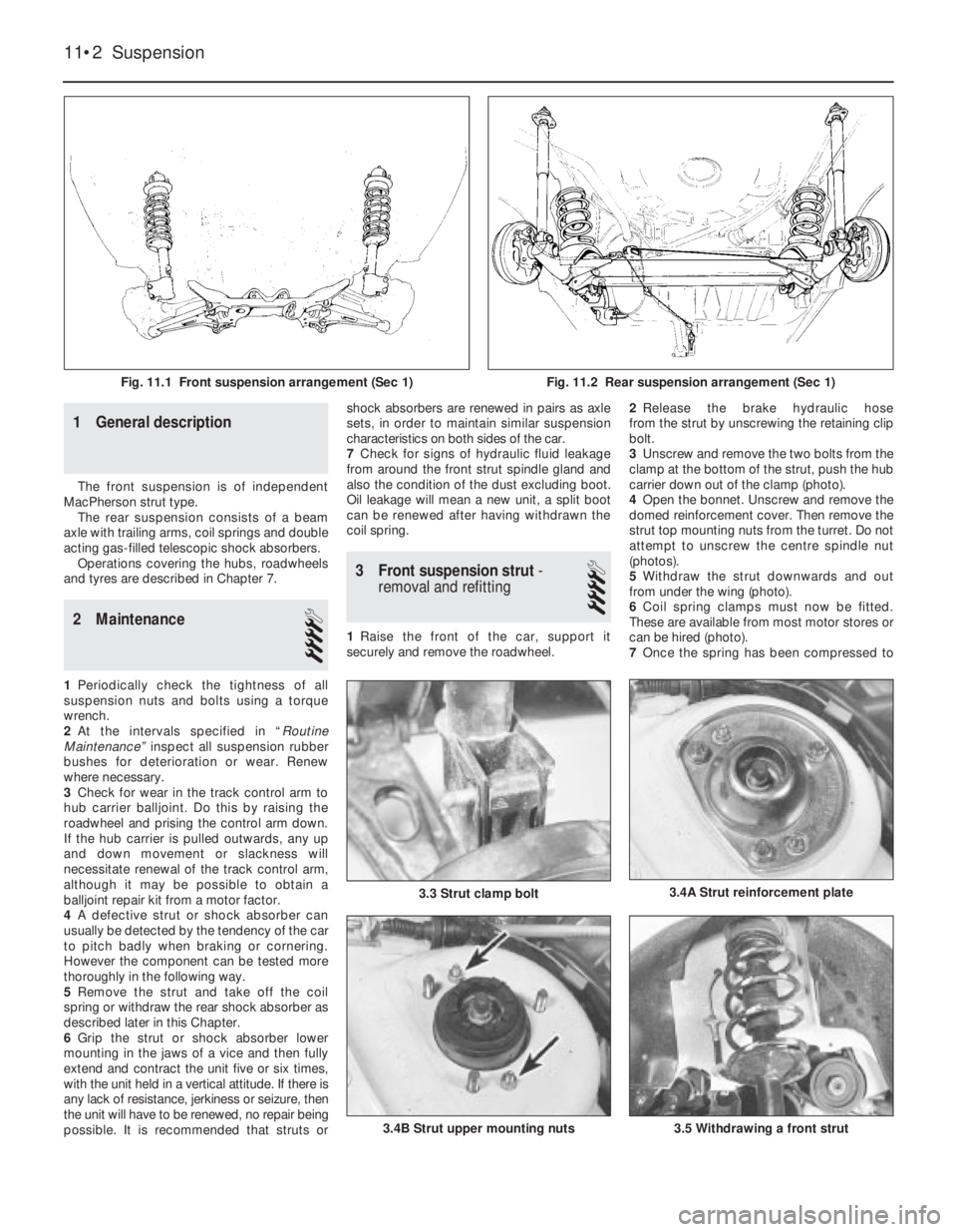
1 General description
The front suspension is of independent
MacPherson strut type.
The rear suspension consists of a beam
axle with trailing arms, coil springs and double
acting gas-filled telescopic shock absorbers.
Operations covering the hubs, roadwheels
and tyres are described in Chapter 7.
2 Maintenance
4
1Periodically check the tightness of all
suspension nuts and bolts using a torque
wrench.
2At the intervals specified in “Routine
Maintenance” inspect all suspension rubber
bushes for deterioration or wear. Renew
where necessary.
3Check for wear in the track control arm to
hub carrier balljoint. Do this by raising the
roadwheel and prising the control arm down.
If the hub carrier is pulled outwards, any up
and down movement or slackness will
necessitate renewal of the track control arm,
although it may be possible to obtain a
balljoint repair kit from a motor factor.
4A defective strut or shock absorber can
usually be detected by the tendency of the car
to pitch badly when braking or cornering.
However the component can be tested more
thoroughly in the following way.
5Remove the strut and take off the coil
spring or withdraw the rear shock absorber as
described later in this Chapter.
6Grip the strut or shock absorber lower
mounting in the jaws of a vice and then fully
extend and contract the unit five or six times,
with the unit held in a vertical attitude. If there is
any lack of resistance, jerkiness or seizure, then
the unit will have to be renewed, no repair being
possible. It is recommended that struts orshock absorbers are renewed in pairs as axle
sets, in order to maintain similar suspension
characteristics on both sides of the car.
7Check for signs of hydraulic fluid leakage
from around the front strut spindle gland and
also the condition of the dust excluding boot.
Oil leakage will mean a new unit, a split boot
can be renewed after having withdrawn the
coil spring.
3 Front suspension strut-
removal and refitting
4
1Raise the front of the car, support it
securely and remove the roadwheel.2Release the brake hydraulic hose
from the strut by unscrewing the retaining clip
bolt.
3Unscrew and remove the two bolts from the
clamp at the bottom of the strut, push the hub
carrier down out of the clamp (photo).
4Open the bonnet. Unscrew and remove the
domed reinforcement cover. Then remove the
strut top mounting nuts from the turret. Do not
attempt to unscrew the centre spindle nut
(photos).
5Withdraw the strut downwards and out
from under the wing (photo).
6Coil spring clamps must now be fitted.
These are available from most motor stores or
can be hired (photo).
7Once the spring has been compressed to
11•2 Suspension
3.5 Withdrawing a front strut3.4B Strut upper mounting nuts
3.4A Strut reinforcement plate3.3 Strut clamp bolt
Fig. 11.1 Front suspension arrangement (Sec 1)Fig. 11.2 Rear suspension arrangement (Sec 1)
Page 111 of 303
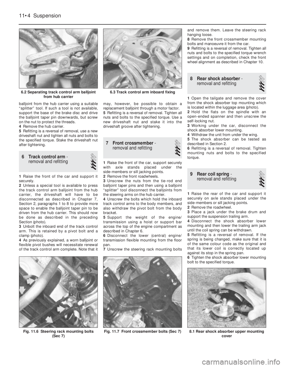
balljoint from the hub carrier using a suitable
“splitter” tool. If such a tool is not available,
support the base of the brake disc and drive
the balljoint taper pin downwards, but screw
on the nut to protect the threads.
4Remove the hub carrier.
5Refitting is a reversal of removal, use a new
driveshaft nut and tighten all nuts and bolts to
the specified torque. Stake the driveshaft nut
after tightening.
6 Track control arm-
removal and refitting
3
1Raise the front of the car and support it
securely.
2Unless a special tool is available to press
the track control arm balljoint from the hub
carrier, the driveshaft will have to be
disconnected as described in Chapter 7,
Section 2, paragraphs 1 to 8 to provide more
space to enable the balljoint taper pin to be
driven from the hub carrier. This should now
be done as described in the preceding
Section (photo).
3Unbolt the inboard end of the track control
arm. This is retained by a pivot bolt and a
clamp (photo).
4As previously explained, a worn balljoint or
flexible pivot bushes will necessitate renewal
of the track control arm complete. Note that itmay, however, be possible to obtain a
replacement balljoint through a motor factor.
5Refitting is a reversal of removal. Tighten all
nuts and bolts to the specified torque. Use a
new driveshaft nut and stake it into the
driveshaft groove after tightening.
7 Front crossmember-
removal and refitting
3
1Raise the front of the car, support securely
with axle stands placed under the
side-members or sill jacking points.
2Remove the front roadwheels.
3Unscrew the nuts from the tie-rod end
balljoint taper pins and then using a balljoint
“splitter” tool disconnect the balljoints from
the steering arms on the hub carrier.
4Unscrew the bolts which hold the inboard
track control arms to the body members, and
also withdraw the pivot bolt from the body
bracket.
5Support the weight of the engine/
transmission using a hoist or support bar
across the top of the engine compartment as
described in Chapter 6.
6Disconnect the lower (central) engine/
transmission flexible mounting from the floor
pan.
7Unscrew the steering rack mounting boltsand remove them. Leave the steering rack
hanging loose.
8Remove the front crossmember mounting
bolts and manoeuvre it from the car.
9Refitting is a reversal of removal. Tighten all
nuts and bolts to the specified torque wrench
settings and on completion, check the front
wheel alignment as described in Chapter 10.
8 Rear shock absorber-
removal and refitting
3
1Open the tailgate and remove the cover
from the shock absorber top mounting which
is located within the luggage area (photo).
2Hold the flats on the spindle with an
open-ended spanner and then unscrew the
self-locking nut.
3Working under the car, disconnect the
shock absorber lower mounting.
4Withdraw the unit from under the wing.
5The shock absorber can be tested as
described in Section 2.
6Refitting is a reversal of removal. Tighten
mounting nuts and bolts to the specified
torque.
9 Rear coil spring-
removal and refitting
3
1Raise the rear of the car and support it
securely on axle stands placed under the
side-members or sill jacking points.
2Remove the roadwheel.
3Place a jack under the brake drum and
support the suspension trailing arm.
4Disconnect the shock absorber lower
mounting and then lower the trailing arm jack
until the coil spring can be withdrawn.
5Refitting is a reversal of removal. If the
spring is being changed, make sure that it is
of the same colour code as the original and
that its lower coil is correctly located up
against its stop in the spring pan.
6Tighten the shock absorber lower mounting
bolt to the specified torque.
11•4 Suspension
8.1 Rear shock absorber upper mounting
coverFig. 11.7 Front crossmember bolts (Sec 7)Fig. 11.6 Steering rack mounting bolts
(Sec 7)
6.3 Track control arm inboard fixing6.2 Separating track control arm balljoint
from hub carrier