oil level FIAT UNO 1983 Service Repair Manual
[x] Cancel search | Manufacturer: FIAT, Model Year: 1983, Model line: UNO, Model: FIAT UNO 1983Pages: 303, PDF Size: 10.36 MB
Page 8 of 303
0•8Roadside Repairs
To avoid repetition, the procedure for
raising the vehicle, in order to carry out work
under it, is not included before each relevant
operation described in this Manual.
It is to be preferred, and it is certainly
recommended, that the vehicle is positioned
over an inspection pit or raised on a lift. Where
these facilities are not available, use ramps or
jack up the vehicle strictly in accordance with
the following guide. Once the vehicle is raised,
supplement the jack with axle stands.
Jacking
The jack supplied with the car should only
be used to change a wheel. Do not use this
jack when overhaul or repair work is being
carried out; employ a hydraulic or screw jack
and supplement it with axle stands.
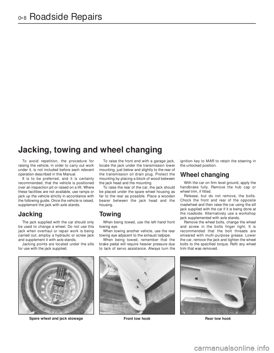
Jacking points are located under the sills
for use with the jack supplied.To raise the front end with a garage jack,
locate the jack under the transmission lower
mounting, just below and slightly to the rear of
the transmission oil drain plug. Protect the
mounting by placing a block of wood between
the jack head and the mounting.
To raise the rear of the car, the jack should
be placed under the spare wheel housing as
far to the rear as possible. Place a wooden
bearer between the jack head and the
housing.
Towing
When being towed, use the left-hand front
towing eye.
When towing another vehicle, use the rear
towing eye adjacent to the exhaust tailpipe.
When being towed, remember that the
brake pedal will require heavier pressure due
to lack of servo assistance. Always turn theignition key to MAR to retain the steering in
the unlocked position.
Wheel changing
With the car on firm level ground, apply the
handbrake fully. Remove the hub cap or
wheel trim, if fitted.
Release, but do not remove, the bolts.
Chock the front and rear of the opposite
roadwheel and then raise the car using the sill
jack supplied with the car if it is being done at
the roadside. Alternatively use a workshop
jack supplemented with axle stands.
Remove the wheel bolts, change the wheel
and screw in the bolts finger tight. It is
recommended that the bolt threads are
smeared with multi-purpose grease. Lower
the car, remove the jack and tighten the wheel
bolts to the specified torque. Refit any wheel
trim that was removed.
Spare wheel and jack stowage
Front tow hook Rear tow hook
Jacking, towing and wheel changing
Page 10 of 303
0•10Routine maintenance
Maintenance is essential for ensuring safety and desirable for the
purpose of getting the best in terms of performance and economy
from the car. Over the years the need for periodic lubrication has been
greatly reduced if not totally eliminated. This has unfortunately tended
to lead some owners to think that because no such action is required
the items either no longer exist or will last forever. This is certainly not
the case; it is essential to carry out regular visual examinations as
comprehensively as possible in order to spot any possible defects at
an early stage before they develop into major and expensive repairs.
For information applicable to later models, see Supplement.
Every 250 miles (400 km), weekly,
or before a long journey
m mCheck engine oil level
m mCheck brake reservoir fluid level
m mCheck tyre pressures
m mCheck operation of all lights and horn
m mTop up washer fluid reservoirs, adding a screen
wash, and check operation of washers and wipers
m mCheck coolant level
m mCheck battery electrolyte level
Every 6000 miles (10 000 km)
or six months, whichever comes first
m mRenew engine oil and filter (Chapter 1, Section 2)
m mCheck drivebelt tension (Chapter 2, Section 8)
m mCheck carburettor idle speed and mixture
adjustments (Chapter 3)
m mCheck contact points and dwell angle (mechanical
breaker distributors) (Chapter 4, Section 3)
m mCheck tyre tread wear (Chapter 7, Section 7)
m mCheck disc pads for wear (Chapter 8, Section 3)
Every 36 000 miles (60 000 km)
or three years, whichever comes first
m mRenew the timing belt - 1116 and 1299/1301 cc
(Chapter 1, Section 28)
m mCheck exhaust system for corrosion (Chapter 3,
Section 19)
m mRenew contact breaker points and adjust dwell
angle (mechanical breaker distributors) (Chapter 4,
Section 3)
m mCheck and adjust ignition timing (Chapter 4,
Section 4)
m mRenew spark plugs (Chapter 4, Section 11)
m mCheck clutch adjustment (Chapter 5, Section 2)
m mCheck transmission oil level (Chapter 6, Section 2)
m mCheck driveshaft and steering rack gaiters for splits
(Chapters 7 and 10)
m mCheck rear brake shoe linings for wear (Chapter 8,
Section 4)
m mCheck handbrake travel (Chapter 8, Section 16)
m mCheck headlamp beam alignment (Chapter 9,
Section 17)
m mCheck balljoints for wear (Chapter 10, Section 2)
m mCheck front wheel alignment (Chapter 10, Section 8)
m mCheck suspension bushes for wear (Chapter 11,
Section 2)
m mCheck seat belts for fraying (Chapter 12, Section 23)
m mLubricate controls, hinges and locks
Every 24 000 miles (40 000 km)
or two years, whichever comes first
m mRenew coolant anti-freeze mixture (Chapter 2,
Section 3)
m mRenew transmission oil (Chapter 6, Section 2)
m mRenew brake hydraulic fluid (Chapter 8, Section 12)
m mCheck for underbody corrosion and clean out door
and sill drain holes (Chapter 12, Section 2)
Every 12 000 miles (20 000 km) or
12 months, whichever comes first
m mCheck and adjust valve clearances (Chapter 1,
Sections 5 and 26)
m mRenew air cleaner element (Chapter 3, Section 2)
Page 22 of 303
2 Engine oil and filter
1
1The engine oil level should be checked at
the weekly service (see “Routine
Maintenance”). Preferably check the level
cold, first thing in the morning or if the engine
has been running, allow at least ten minutes
to elapse after switching off to permit the oil to
drain.
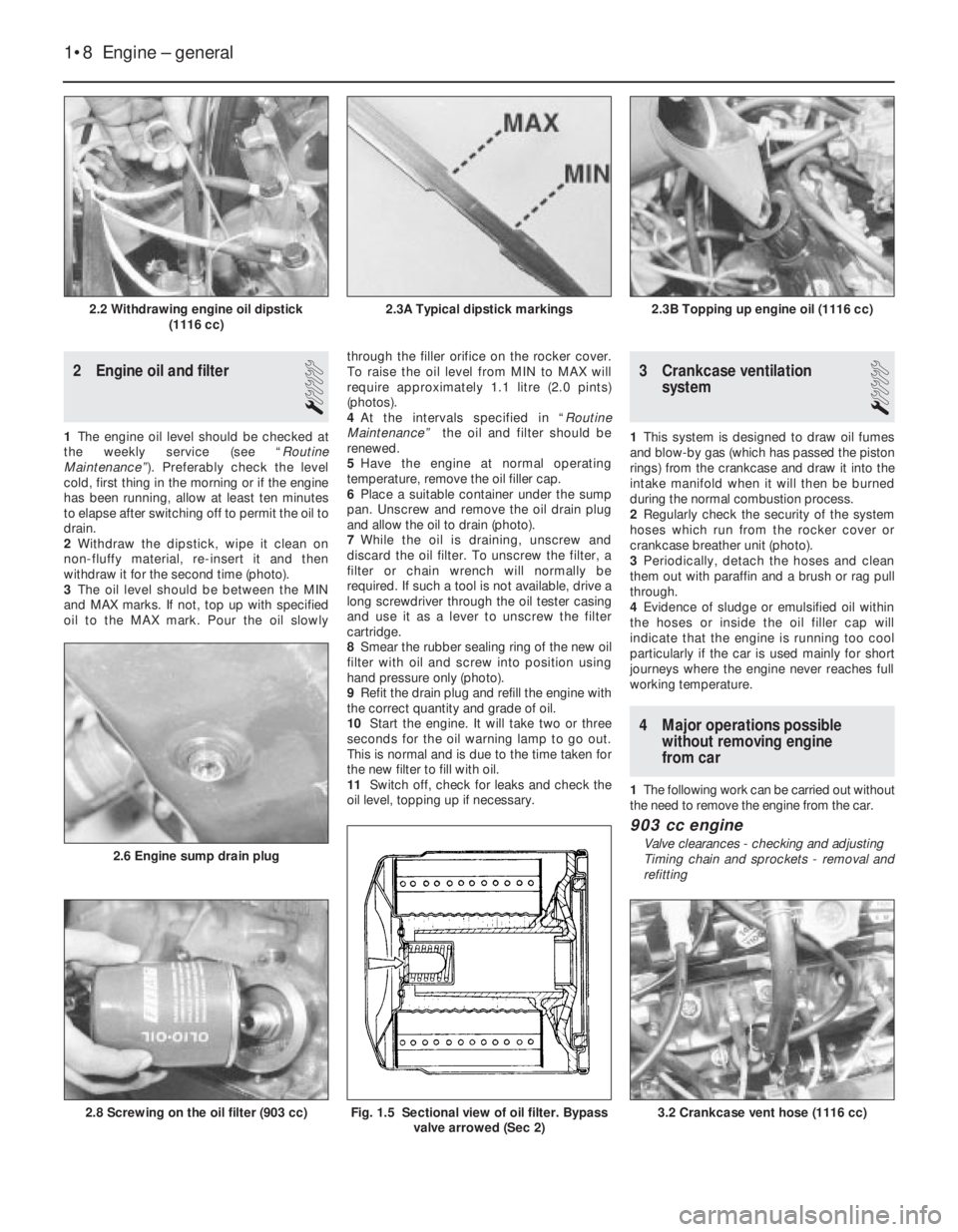
2Withdraw the dipstick, wipe it clean on
non-fluffy material, re-insert it and then
withdraw it for the second time (photo).
3The oil level should be between the MIN
and MAX marks. If not, top up with specified
oil to the MAX mark. Pour the oil slowlythrough the filler orifice on the rocker cover.
To raise the oil level from MIN to MAX will
require approximately 1.1 litre (2.0 pints)
(photos).
4At the intervals specified in “Routine
Maintenance” the oil and filter should be
renewed.
5Have the engine at normal operating
temperature, remove the oil filler cap.
6Place a suitable container under the sump
pan. Unscrew and remove the oil drain plug
and allow the oil to drain (photo).
7While the oil is draining, unscrew and
discard the oil filter. To unscrew the filter, a
filter or chain wrench will normally be
required. If such a tool is not available, drive a
long screwdriver through the oil tester casing
and use it as a lever to unscrew the filter
cartridge.
8Smear the rubber sealing ring of the new oil
filter with oil and screw into position using
hand pressure only (photo).
9Refit the drain plug and refill the engine with
the correct quantity and grade of oil.
10Start the engine. It will take two or three
seconds for the oil warning lamp to go out.
This is normal and is due to the time taken for
the new filter to fill with oil.
11Switch off, check for leaks and check the
oil level, topping up if necessary.
3 Crankcase ventilation
system
1
1This system is designed to draw oil fumes
and blow-by gas (which has passed the piston
rings) from the crankcase and draw it into the
intake manifold when it will then be burned
during the normal combustion process.
2Regularly check the security of the system
hoses which run from the rocker cover or
crankcase breather unit (photo).
3Periodically, detach the hoses and clean
them out with paraffin and a brush or rag pull
through.
4Evidence of sludge or emulsified oil within
the hoses or inside the oil filler cap will
indicate that the engine is running too cool
particularly if the car is used mainly for short
journeys where the engine never reaches full
working temperature.
4 Major operations possible
without removing engine
from car
1The following work can be carried out without
the need to remove the engine from the car.
903 cc engine
Valve clearances - checking and adjusting
Timing chain and sprockets - removal and
refitting
1•8 Engine – general
3.2 Crankcase vent hose (1116 cc)Fig. 1.5 Sectional view of oil filter. Bypass
valve arrowed (Sec 2)2.8 Screwing on the oil filter (903 cc)
2.6 Engine sump drain plug
2.3B Topping up engine oil (1116 cc)2.3A Typical dipstick markings2.2 Withdrawing engine oil dipstick
(1116 cc)
Page 48 of 303
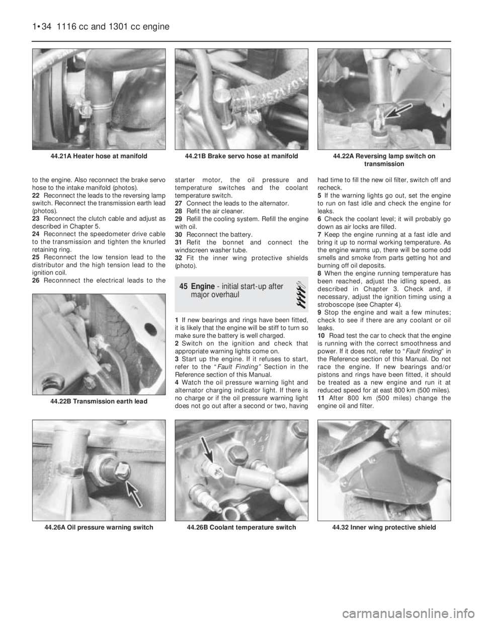
to the engine. Also reconnect the brake servo
hose to the intake manifold (photos).
22Reconnect the leads to the reversing lamp
switch. Reconnect the transmission earth lead
(photos).
23Reconnect the clutch cable and adjust as
described in Chapter 5.
24Reconnect the speedometer drive cable
to the transmission and tighten the knurled
retaining ring.
25Reconnect the low tension lead to the
distributor and the high tension lead to the
ignition coil.
26Reconnnect the electrical leads to thestarter motor, the oil pressure and
temperature switches and the coolant
temperature switch.
27Connect the leads to the alternator.
28Refit the air cleaner.
29Refill the cooling system. Refill the engine
with oil.
30Reconnect the battery.
31Refit the bonnet and connect the
windscreen washer tube.
32Fit the inner wing protective shields
(photo).
45 Engine- initial start-up after
major overhaul
4
1If new bearings and rings have been fitted,
it is likely that the engine will be stiff to turn so
make sure the battery is well charged.
2Switch on the ignition and check that
appropriate warning lights come on.
3Start up the engine. If it refuses to start,
refer to the “Fault Finding” Section in the
Reference section of this Manual.
4Watch the oil pressure warning light and
alternator charging indicator light. If there is
no charge or if the oil pressure warning light
does not go out after a second or two, havinghad time to fill the new oil filter, switch off and
recheck.
5If the warning lights go out, set the engine
to run on fast idle and check the engine for
leaks.
6Check the coolant level; it will probably go
down as air locks are filled.
7Keep the engine running at a fast idle and
bring it up to normal working temperature. As
the engine warms up, there will be some odd
smells and smoke from parts getting hot and
burning off oil deposits.
8When the engine running temperature has
been reached, adjust the idling speed, as
described in Chapter 3. Check and, if
necessary, adjust the ignition timing using a
stroboscope (see Chapter 4).
9Stop the engine and wait a few minutes;
check to see if there are any coolant or oil
leaks.
10Road test the car to check that the engine
is running with the correct smoothness and
power. If it does not, refer to “Fault finding” in
the Reference section of this Manual. Do not
race the engine. If new bearings and/or
pistons and rings have been fitted, it should
be treated as a new engine and run it at
reduced speed for at east 800 km (500 miles).
11After 800 km (500 miles) change the
engine oil and filter.
1•34 1116 cc and 1301 cc engine
44.32 Inner wing protective shield44.26B Coolant temperature switch44.26A Oil pressure warning switch
44.22B Transmission earth lead
44.22A Reversing lamp switch on
transmission44.21B Brake servo hose at manifold44.21A Heater hose at manifold
Page 50 of 303
Engine idles roughly
m mMixture too weak
m mAir leak in carburettor
m mAir leak at inlet manifold to cylinder head, or inlet manifold to
carburettor
m mCarburettor incorrectly adjusted
m mOther fuel system fault (see Chapter 3)
m mLow tension leads on coil loose
m mLow tension lead to distributor loose
m mDirty, incorrectly set, or pitted contact breaker points
m mTracking across inside of distributor cover
m mFaulty coil
m mIgnition leads loose
m mSpark plugs fouled or incorrectly gapped.
m mIgnition timing incorrect
m mOther ignition fault (see Chapter 4)
m mIncorrect valve clearances
m mWidely differing cylinder compressions
m mLow battery voltage (charging fault)
m mBattery leads loose on terminals
m mBattery earth strap loose on body attachment point
m mEngine earth lead loose
Pre-ignition (pinking) during acceleration
m
mIncorrect grade of fuel being used
m mIgnition timing over-advanced
m mOther ignition fault (see Chapter 4)
m mEngine overheated
m mExcessive carbon build-up
m mFuel system fault (see Chapter 3)
m mValve timing incorrect (after rebuild)
m mMixture too weak
Engine runs on after switching off
m
mIdle speed too high
m mIncorrect type of spark plug
m mOverheating
m mExcessive carbon build-up
m mOther emission control fault (see Chapter 3)
Oil being lost due to leaks
m
mLeaking oil filter gasket
m mLeaking rocker cover gasket
m mLeaking timing gear cover gasket
m mLeaking sump gasket
m mLoose sump plug
Low oil pressure (verify accuracy of sender before
dismantling engine!)
m mOil level low
m mEngine overheating
m mIncorrect grade of oil in use
m mOil filter clogged or bypass valve stuck
m mPressure relief valve stuck or defective
m mOil pick-up strainer clogged or loose
m mMain or big-end bearings worn
m mOil pump worn or mountings loose
Excessive oil consumption
m
mOverfilling
m mLeaking gaskets or drain plug washer
m mValve stem oil seals worn, damaged or missing after rebuild
m mValve stems and/or guides worn
m mPiston rings and/or bores worn
m mPiston oil return holes clogged
Oil contaminated with water
m
mExcessive cold running
m mLeaking head gasket
m mCracked block or head
Oil contaminated with fuel
m
mExcessive use of choke
m mWorn piston rings and/or bores
Unusual mechanical noises
m
mUnintentional mechanical contact (eg fan blade)
m mWorn drivebelt
m mWorn valvegear (tapping noises from top of engine) or incorrect
clearance
m mPeripheral component fault (generator, coolant pump)
m mWorn big-end bearings (regular heavy knocking, perhaps less under
load)
m mWorn main bearings (rumbling and knocking, perhaps worsening
under load)
m mSmall-end bushes or gudgeon pins worn (light metallic tapping)
m mPiston slap (most noticeable when engine cold)
m mWorn timing chain and gears (rattling from front of engine)
m mWorn crankshaft (knocking, rumbling and vibration)
1•36 All engines
Page 51 of 303
2
System type . . . . . . . . . . . . . . . . . . . . . . . . . . . . . . . . . . . . . . . . . . . “No loss” with radiator and integral expansion tank. Electric cooling
fan, belt-driven coolant pump, thermostat on cylinder head
General
Radiator fan cuts in . . . . . . . . . . . . . . . . . . . . . . . . . . . . . . . . . . . . . . . . . 90 to 94ºC (194 to 201ºF)
Radiator fan switches off . . . . . . . . . . . . . . . . . . . . . . . . . . . . . . . . . . . . 85 to 89ºC (185 to 192ºF)
Thermostat opens:
903 cc engine . . . . . . . . . . . . . . . . . . . . . . . . . . . . . . . . . . . . . . . . . . . 85 to 89ºC (185 to 192ºF)
1116 cc and 1301 cc engines . . . . . . . . . . . . . . . . . . . . . . . . . . . . . . . 83 to 87ºC (181 to 188.6ºF)
Fully open:
903 cc . . . . . . . . . . . . . . . . . . . . . . . . . . . . . . . . . . . . . . . . . . . . . . . . . 100ºC (212ºF)
1116 cc and 1301 cc . . . . . . . . . . . . . . . . . . . . . . . . . . . . . . . . . . . . . 95ºC (203ºF)
Expansion tank pressure cap rating . . . . . . . . . . . . . . . . . . . . . . . . . . . . 0.78 bar (11 lbf/in2)
Coolant
Capacity:
903 cc . . . . . . . . . . . . . . . . . . . . . . . . . . . . . . . . . . . . . . . . . . . . . . . . . 4.6 litre (8.1 pint)
1116 cc . . . . . . . . . . . . . . . . . . . . . . . . . . . . . . . . . . . . . . . . . . . . . . . . 6.0 litre (10.6 pint)
1301 cc . . . . . . . . . . . . . . . . . . . . . . . . . . . . . . . . . . . . . . . . . . . . . . . . 6.2 litre (10.9 pint)
Type . . . . . . . . . . . . . . . . . . . . . . . . . . . . . . . . . . . . . . . . . . . . . . . . . . . . Ethylene glycol based antifreeze
Torque wrench settingsNm lbf ft
Temperature sender switch . . . . . . . . . . . . . . . . . . . . . . . . . . . . . . . . . . 49 36
Coolant pump mounting bolts . . . . . . . . . . . . . . . . . . . . . . . . . . . . . . . . 34 25
Alternator adjuster and mountings nuts . . . . . . . . . . . . . . . . . . . . . . . . . 49 36
Chapter 2 Cooling and heating systems
For modifications, and information applicable to later models, see Supplement at end of manual
Coolant mixtures . . . . . . . . . . . . . . . . . . . . . . . . . . . . . . . . . . . . . . . . 3
Coolant pump - removal, overhaul and refitting . . . . . . . . . . . . . . . . 9
Cooling system - draining, flushing and refilling . . . . . . . . . . . . . . . . 2
Cooling system sensors . . . . . . . . . . . . . . . . . . . . . . . . . . . . . . . . . . 10
Description and maintenance . . . . . . . . . . . . . . . . . . . . . . . . . . . . . . 1
Drivebelt - tensioning and renewal . . . . . . . . . . . . . . . . . . . . . . . . . . 8
Fault finding - cooling and heating . . . . . . . . . . . . See end of ChapterHeater - dismantling, overhaul and reassembly . . . . . . . . . . . . . . . . 13
Heater unit - removal and refitting . . . . . . . . . . . . . . . . . . . . . . . . . . 12
Heating and ventilation system - description . . . . . . . . . . . . . . . . . . 11
Radiator - removal and refitting . . . . . . . . . . . . . . . . . . . . . . . . . . . . 7
Radiator fan thermostatic switch - removal, checking and refitting . 5
Radiator fan - removal and refitting . . . . . . . . . . . . . . . . . . . . . . . . . 6
Thermostat - removal, testing and refitting . . . . . . . . . . . . . . . . . . . . 4
2•1
Specifications Contents
1 Description and
maintenance
1
1The cooling system consists of a
front-mounted radiator with built-in expansion
tank, a coolant pump (belt-driven from the
crankshaft pulley) and a thermostatically-
controlled electric cooling fan.
2In order to assist rapid warm-up, athermostat is located in a housing at the
left-hand end of the cylinder head. The hose
connections to the thermostat housing vary
according to model.
3The heater is supplied with coolant from the
engine and incorporates a matrix and blower
with the necessary controls.
4The throttle valve plate block of the
carburettor is coolant-heated as a means of
improving fuel atomisation.
5Maintenance is minimal as in theory no
coolant should ever be lost from theexpansion tank. Regularly check that the
coolant level is between 50.0 and 70.0 mm
(1.97 and 2.8 in) above the MIN mark on the
tank with the engine cold. The need for
regular topping up will indicate a leak
somewhere in the system. If one cannot be
found suspect an internal leak in the engine
although this is usually confirmed by a rise in
the engine oil level and water on the dipstick
(photo). Any topping-up should be done using
an antifreeze mixture (see Section 3), not plain
water.
Easy,suitable for
novice with little
experienceFairly easy,suitable
for beginner with
some experienceFairly difficult,
suitable for competent
DIY mechanic
Difficult,suitable for
experienced DIY
mechanicVery difficult,
suitable for expert DIY
or professional
Degrees of difficulty
54321
Page 52 of 303
6Avoid unscrewing the expansion tank cap
when the engine is hot, but if this must be
done, cover the cap with a cloth to avoid
scalding by escaping steam.
7Periodically, check the condition of all
coolant hoses and tighten the clips.
2 Cooling system- draining,
flushing and refilling
1
1Set the heater temperature lever to
maximum.
2Unscrew the cap from the expansion tank.
3Disconnect the radiator bottom hose and
unscrew the cylinder block drain plug (1116
cc and 1301 cc engines) and allow the coolant
to drain. Refer to photo 29.21B, page 64.
4If the system is in good condition with no
sign of rust or dirt in the drained coolant, then
it may be refilled immediately. If the system
has been neglected and the antifreeze has notbeen regularly renewed and there is evidence
of rust and sediment in the drained liquid then
flush the system through with a cold water
hose.
5If the radiator should appear to be clogged,
it may be necessary to remove it (Section 7)
invert it and reverse flush it using a cold water
hose. If, after a reasonable period the water
still does not run clear, the radiator should be
flushed with a good proprietary cleaning
system. Extensive damage should be repaired
by a specialist or the unit exchanged for a
new or reconditioned radiator.
6Reconnect the bottom hose and screw in
the drain plug.
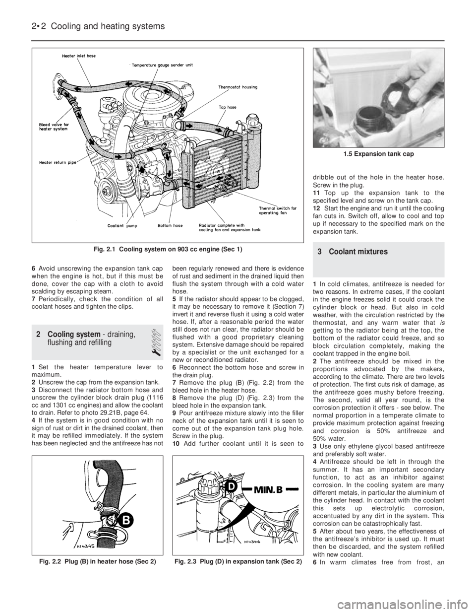
7Remove the plug (B) (Fig. 2.2) from the
bleed hole in the heater hose.
8Remove the plug (D) (Fig. 2.3) from the
bleed hole in the expansion tank.
9Pour antifreeze mixture slowly into the filler
neck of the expansion tank until it is seen to
come out of the expansion tank plug hole.
Screw in the plug.
10Add further coolant until it is seen todribble out of the hole in the heater hose.
Screw in the plug.
11Top up the expansion tank to the
specified level and screw on the tank cap.
12Start the engine and run it until the cooling
fan cuts in. Switch off, allow to cool and top
up if necessary to the specified mark on the
expansion tank.
3 Coolant mixtures
1In cold climates, antifreeze is needed for
two reasons. In extreme cases, if the coolant
in the engine freezes solid it could crack the
cylinder block or head. But also in cold
weather, with the circulation restricted by the
thermostat, and any warm water that is
getting to the radiator being at the top, the
bottom of the radiator could freeze, and so
block circulation completely, making the
coolant trapped in the engine boil.
2The antifreeze should be mixed in the
proportions advocated by the makers,
according to the climate. There are two levels
of protection. The first cuts risk of damage, as
the antifreeze goes mushy before freezing.
The second, valid all year round, is the
corrosion protection it offers - see below. The
normal proportion in a temperate climate to
provide maximum protection against freezing
and corrosion is 50% antifreeze and
50% water.
3Use only ethylene glycol based antifreeze
and preferably soft water.
4Antifreeze should be left in through the
summer. It has an important secondary
function, to act as an inhibitor against
corrosion. In the cooling system are many
different metals, in particular the aluminium of
the cylinder head. In contact with the coolant
this sets up electrolytic corrosion,
accentuated by any dirt in the system. This
corrosion can be catastrophically fast.
5After about two years, the effectiveness of
the antifreeze’s inhibitor is used up. It must
then be discarded, and the system refilled
with new coolant.
6In warm climates free from frost, an
2•2 Cooling and heating systems
Fig. 2.3 Plug (D) in expansion tank (Sec 2)Fig. 2.2 Plug (B) in heater hose (Sec 2)
1.5 Expansion tank cap
Fig. 2.1 Cooling system on 903 cc engine (Sec 1)
Page 58 of 303
Fault finding - cooling and heating systems
2•8 Cooling and heating systems
Overheating
m mInsufficient coolant in system
m mPump ineffective due to slack drivebelt
m mRadiator blocked either internally or externally
m mKinked or collapsed hose causing coolant flow restriction
m mThermostat not working properly
m mEngine out of tune
m mIgnition timing retarded or auto advance malfunction
m mCylinder head gasket blown
m mEngine not yet run-in
m mExhaust system partially blocked
m mEngine oil level too low
m mBrakes binding
Engine running too cool
m
mFaulty, incorrect or missing thermostat
Loss of coolant
m
mLoose hose clips
m mHoses perished or leaking
m mRadiator leaking
m mFiller/pressure cap defective
m mBlown cylinder head gasket
m mCracked cylinder block or head
Heater gives insufficient output
m
mEngine overcooled (see above)
m mHeater matrix blocked
m mHeater controls maladjusted or broken
m mHeater control valve jammed or otherwise
defective
Page 83 of 303
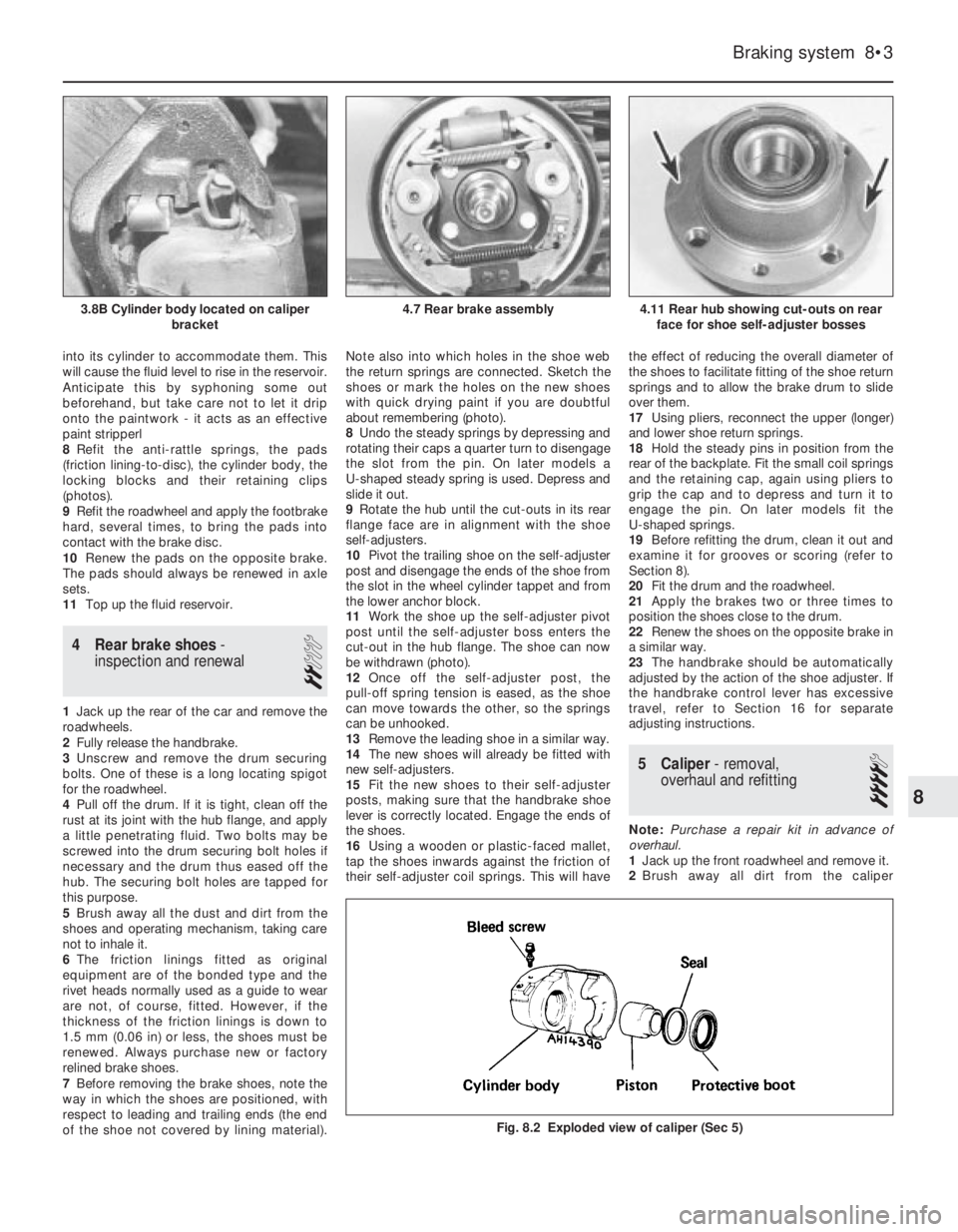
into its cylinder to accommodate them. This
will cause the fluid level to rise in the reservoir.
Anticipate this by syphoning some out
beforehand, but take care not to let it drip
onto the paintwork - it acts as an effective
paint stripperl
8Refit the anti-rattle springs, the pads
(friction lining-to-disc), the cylinder body, the
locking blocks and their retaining clips
(photos).
9Refit the roadwheel and apply the footbrake
hard, several times, to bring the pads into
contact with the brake disc.
10Renew the pads on the opposite brake.
The pads should always be renewed in axle
sets.
11Top up the fluid reservoir.
4 Rear brake shoes-
inspection and renewal
2
1Jack up the rear of the car and remove the
roadwheels.
2Fully release the handbrake.
3Unscrew and remove the drum securing
bolts. One of these is a long locating spigot
for the roadwheel.
4Pull off the drum. lf it is tight, clean off the
rust at its joint with the hub flange, and apply
a little penetrating fluid. Two bolts may be
screwed into the drum securing bolt holes if
necessary and the drum thus eased off the
hub. The securing bolt holes are tapped for
this purpose.
5Brush away all the dust and dirt from the
shoes and operating mechanism, taking care
not to inhale it.
6The friction linings fitted as original
equipment are of the bonded type and the
rivet heads normally used as a guide to wear
are not, of course, fitted. However, if the
thickness of the friction linings is down to
1.5 mm (0.06 in) or less, the shoes must be
renewed. Always purchase new or factory
relined brake shoes.
7Before removing the brake shoes, note the
way in which the shoes are positioned, with
respect to leading and trailing ends (the end
of the shoe not covered by lining material).Note also into which holes in the shoe web
the return springs are connected. Sketch the
shoes or mark the holes on the new shoes
with quick drying paint if you are doubtful
about remembering (photo).
8Undo the steady springs by depressing and
rotating their caps a quarter turn to disengage
the slot from the pin. On later models a
U-shaped steady spring is used. Depress and
slide it out.
9Rotate the hub until the cut-outs in its rear
flange face are in alignment with the shoe
self-adjusters.
10Pivot the trailing shoe on the self-adjuster
post and disengage the ends of the shoe from
the slot in the wheel cylinder tappet and from
the lower anchor block.
11Work the shoe up the self-adjuster pivot
post until the self-adjuster boss enters the
cut-out in the hub flange. The shoe can now
be withdrawn (photo).
12Once off the self-adjuster post, the
pull-off spring tension is eased, as the shoe
can move towards the other, so the springs
can be unhooked.
13Remove the leading shoe in a similar way.
14The new shoes will already be fitted with
new self-adjusters.
15Fit the new shoes to their self-adjuster
posts, making sure that the handbrake shoe
lever is correctly located. Engage the ends of
the shoes.
16Using a wooden or plastic-faced mallet,
tap the shoes inwards against the friction of
their self-adjuster coil springs. This will havethe effect of reducing the overall diameter of
the shoes to facilitate fitting of the shoe return
springs and to allow the brake drum to slide
over them.
17Using pliers, reconnect the upper (longer)
and lower shoe return springs.
18Hold the steady pins in position from the
rear of the backplate. Fit the small coil springs
and the retaining cap, again using pliers to
grip the cap and to depress and turn it to
engage the pin. On later models fit the
U-shaped springs.
19Before refitting the drum, clean it out and
examine it for grooves or scoring (refer to
Section 8).
20Fit the drum and the roadwheel.
21Apply the brakes two or three times to
position the shoes close to the drum.
22Renew the shoes on the opposite brake in
a similar way.
23The handbrake should be automatically
adjusted by the action of the shoe adjuster. If
the handbrake control lever has excessive
travel, refer to Section 16 for separate
adjusting instructions.
5 Caliper- removal,
overhaul and refitting
4
Note: Purchase a repair kit in advance of
overhaul.
1Jack up the front roadwheel and remove it.
2Brush away all dirt from the caliper
Braking system 8•3
4.11 Rear hub showing cut-outs on rear
face for shoe self-adjuster bosses4.7 Rear brake assembly3.8B Cylinder body located on caliper
bracket
Fig. 8.2 Exploded view of caliper (Sec 5)
8
Page 86 of 303
their originally fitted sequence and note in
which direction the seal lips are located.
11Inspect the surfaces of the piston and
cylinder bore. If scoring, corrosion or
metal-to-metal rubbing areas are evident,
renew the master cylinder complete.
12If the components are in good condition,
discard the oil seals and manipulate the new
ones into position, using the fingers only.
13Refit by reversing the removal operations;
apply pressure to the piston ends so that the
stop bolts can be fitted, then tighten the end
plug. Make sure that the grooves in the
pistons engage in the stop bolts.
14Before refitting the master cylinder to the
servo, measure the projection of the servo
piston pushrod. When the master cylinder is
fitted, there must be a clearance (see A in
Fig. 8.7) between the end of the pushrod and
the primary piston end face of between 0.825
and 1.025 mm (0.03 and 0.04 in). A depth
gauge will be required for these
measurements, the reference point being the
mating surfaces of the master cylinder and the
vacuum servo.
15Alter the adjusting screw on the servo as
necessary and lock it by applying locking fluid
to the threads on completion.16Bolt the master cylinder to the vacuum
servo or bulkhead, then reconnect the
pipelines and reservoir cap leads.
17Bleed the complete hydraulic system, as
described in Section 12.
10 Pressure regulating valve
3
1The pressure regulating valve is a load
proportioning valve which restricts the
hydraulic pressure to the rear brakes
according to car weight during heavy
applications of the brake pedal. This prevents
the rear wheels locking.
2A faulty or non-operational valve should be
renewed complete, no repair being possible.
3To remove the valve, unscrew the pipe
unions and disconnect the hydraulic pipes
from the valve. Cap the ends of the pipes to
prevent loss of fluid.
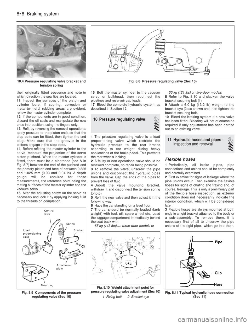
4Unbolt the valve mounting bracket,
withdraw it and disconnect the tension spring
(photo).
5Refit the new valve and then adjust it in the
following way.
6Have the car standing on a level floor.
7The car should be normally loaded (kerb
weight) with fuel, oil, spare wheel etc. Load
the luggage compartment immediately behind
the seat back with:
65 kg (143 lbs) on three-door models or 55 kg (121 lbs) on five-door models
8Refer to Fig. 8.10 and slacken the valve
bracket securing bolt (1).
9Attach a 6.0 kg (13.2 lb) weight to the
bracket eye (2) as shown and then tighten the
bracket securing bolt.
10Bleed the braking system if a new valve
has been fitted. Bleeding will not of course be
required if only adjustment has been carried
out to an existing valve.11 Hydraulic hoses and pipes-
inspection and renewal
3
Flexible hoses
1Periodically, all brake pipes, pipe
connections and unions should be completely
and carefully examined.
2First examine for signs of leakage where the
pipe unions occur. Then examine the flexible
hoses for signs of chafing and fraying and, of
course, leakage. This is only a preliminary part
of the flexible hose inspection, as exterior
condition does not necessarily indicate the
interior condition, which will be considered
later.
3Flexible hoses are always mounted at both
ends in a rigid bracket attached to the body or
a sub-assembly. To remove them, it is
necessary first of all to unscrew the pipe
unions of the rigid pipes which go into them.
8•6 Braking system
Fig. 8.11 Typical hydraulic hose connection
(Sec 11)
Fig. 8.10 Weight attachment point for
pressure regulating valve adjustment (Sec 10)
1 Fixing bolt 2 Bracket eye
Fig. 8.9 Components of the pressure
regulating valve (Sec 10)
Fig. 8.8 Pressure regulating valve (Sec 10)10.4 Pressure regulating valve bracket and
tension spring