clock FORD C MAX 2008 1.G User Guide
[x] Cancel search | Manufacturer: FORD, Model Year: 2008, Model line: C MAX, Model: FORD C MAX 2008 1.GPages: 278, PDF Size: 17.5 MB
Page 172 of 278
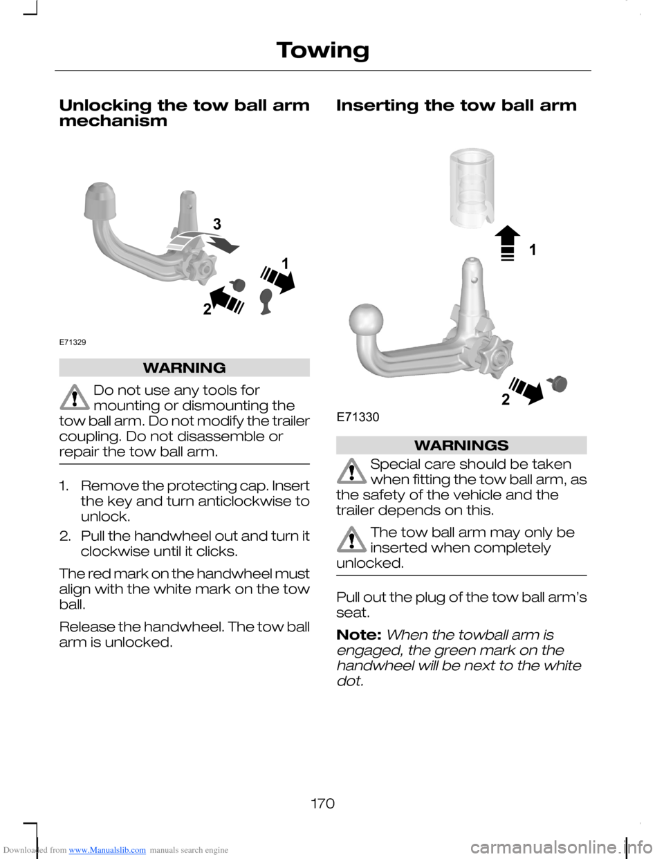
Downloaded from www.Manualslib.com manuals search engine Unlocking the tow ball armmechanism
WARNING
Do not use any tools formounting or dismounting thetow ball arm. Do not modify the trailercoupling. Do not disassemble orrepair the tow ball arm.
1.Remove the protecting cap. Insertthe key and turn anticlockwise tounlock.
2.Pull the handwheel out and turn itclockwise until it clicks.
The red mark on the handwheel mustalign with the white mark on the towball.
Release the handwheel. The tow ballarm is unlocked.
Inserting the tow ball arm
WARNINGS
Special care should be takenwhen fitting the tow ball arm, asthe safety of the vehicle and thetrailer depends on this.
The tow ball arm may only beinserted when completelyunlocked.
Pull out the plug of the tow ball arm’sseat.
Note:When the towball arm isengaged, the green mark on thehandwheel will be next to the whitedot.
170
TowingE71329213 12E71330
Page 173 of 278
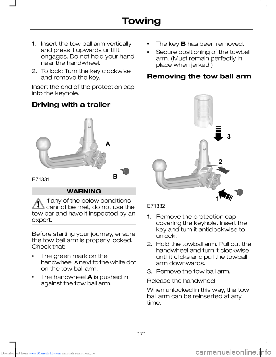
Downloaded from www.Manualslib.com manuals search engine 1.Insert the tow ball arm verticallyand press it upwards until itengages. Do not hold your handnear the handwheel.
2.To lock: Turn the key clockwiseand remove the key.
Insert the end of the protection capinto the keyhole.
Driving with a trailer
WARNING
If any of the below conditionscannot be met, do not use thetow bar and have it inspected by anexpert.
Before starting your journey, ensurethe tow ball arm is properly locked.Check that:
•The green mark on thehandwheel is next to the white doton the tow ball arm.
•The handwheel A is pushed inagainst the tow ball arm.
•The key B has been removed.
•Secure positioning of the towballarm. (Must remain perfectly inplace when jerked.)
Removing the tow ball arm
1.Remove the protection capcovering the keyhole. Insert thekey and turn it anticlockwise tounlock.
2.Hold the towball arm. Pull out thehandwheel and turn it clockwiseuntil it clicks and pull the towballarm downwards.
3.Remove the tow ball arm.
Release the handwheel.
When unlocked in this way, the towball arm can be reinserted at anytime.
171
TowingE71331AB 31E713322
Page 187 of 278
Downloaded from www.Manualslib.com manuals search engine TOWING POINTS
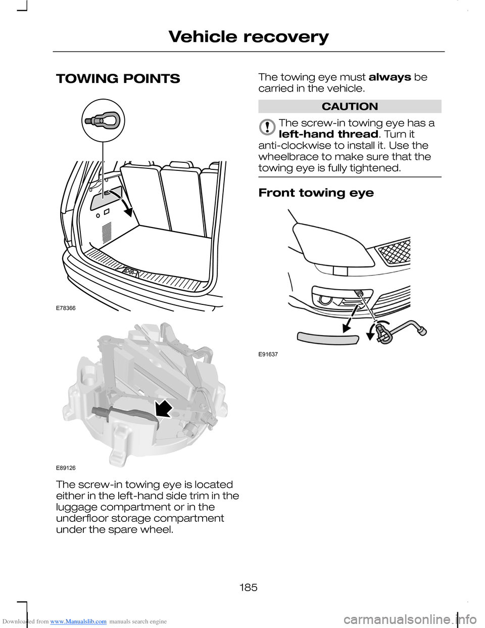
The screw-in towing eye is locatedeither in the left-hand side trim in theluggage compartment or in theunderfloor storage compartmentunder the spare wheel.
The towing eye must always becarried in the vehicle.
CAUTION
The screw-in towing eye has aleft-hand thread. Turn itanti-clockwise to install it. Use thewheelbrace to make sure that thetowing eye is fully tightened.
Front towing eye
185
Vehicle recoveryE78366 E89126 E91637
Page 214 of 278
Downloaded from www.Manualslib.com manuals search engine Vehicles with stability control
Vehicles with ESP may exhibit someunusual driving characteristics. Switchthe ESP off. See Using stabilitycontrol (page 161).
All vehicles
Note:The spare wheel is locatedunder the floor cover in the luggagecompartment.
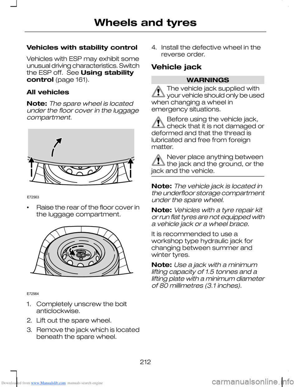
•Raise the rear of the floor cover inthe luggage compartment.
1.Completely unscrew the boltanticlockwise.
2.Lift out the spare wheel.
3.Remove the jack which is locatedbeneath the spare wheel.
4.Install the defective wheel in thereverse order.
Vehicle jack
WARNINGS
The vehicle jack supplied withyour vehicle should only be usedwhen changing a wheel inemergency situations.
Before using the vehicle jack,check that it is not damaged ordeformed and that the thread islubricated and free from foreignmatter.
Never place anything betweenthe jack and the ground, or thejack and the vehicle.
Note:The vehicle jack is located inthe underfloor storage compartmentunder the spare wheel.
Note:Vehicles with a tyre repair kitor run flat tyres are not equipped witha vehicle jack or a wheel brace.
It is recommended to use aworkshop type hydraulic jack forchanging between summer andwinter tyres.
Note:Use a jack with a minimumlifting capacity of 1.5 tonnes and alifting plate with a minimum diameterof 80 millimetres (3.1 inches).
212
Wheels and tyresE72563 E72564
Page 215 of 278
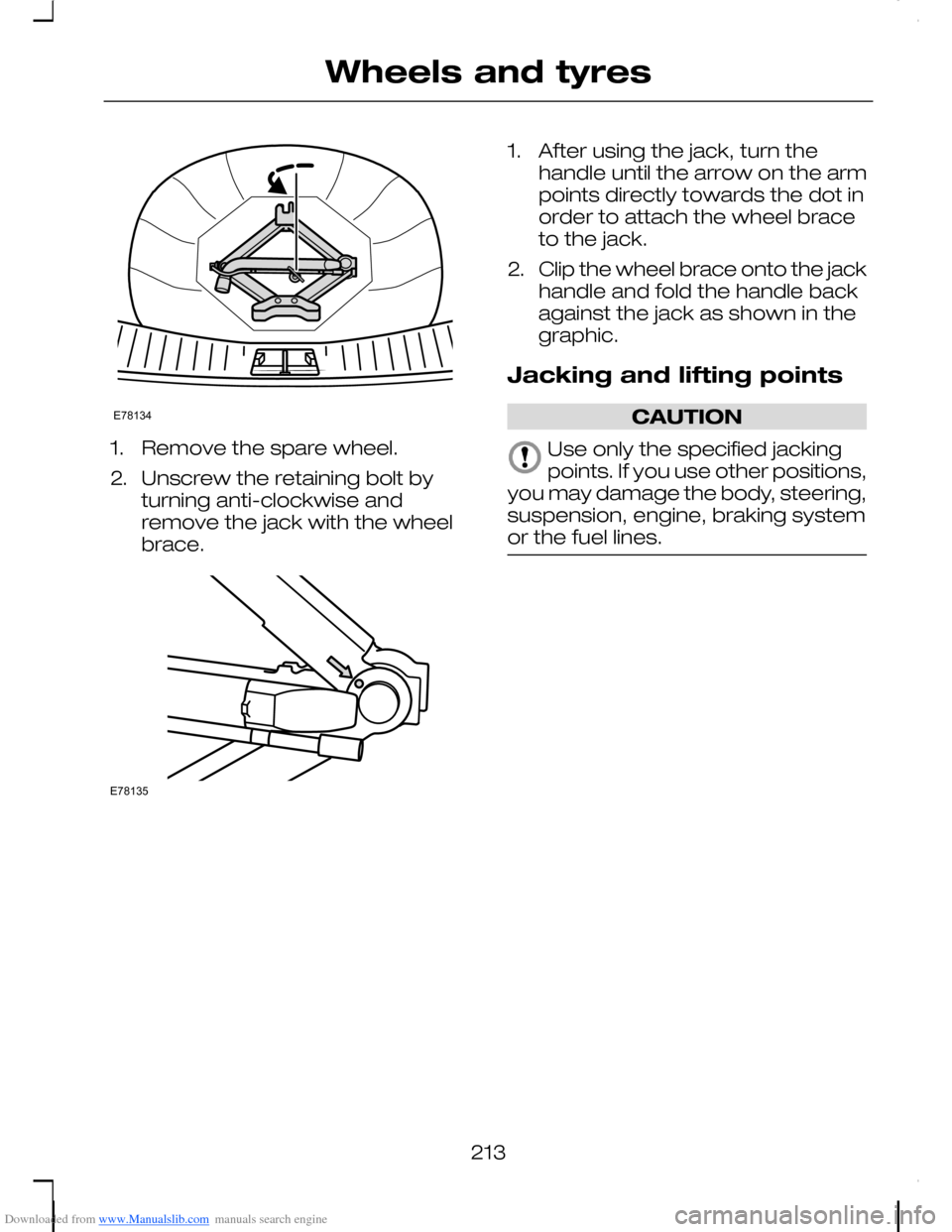
Downloaded from www.Manualslib.com manuals search engine 1.Remove the spare wheel.
2.Unscrew the retaining bolt byturning anti-clockwise andremove the jack with the wheelbrace.
1.After using the jack, turn thehandle until the arrow on the armpoints directly towards the dot inorder to attach the wheel braceto the jack.
2.Clip the wheel brace onto the jackhandle and fold the handle backagainst the jack as shown in thegraphic.
Jacking and lifting points
CAUTION
Use only the specified jackingpoints. If you use other positions,you may damage the body, steering,suspension, engine, braking systemor the fuel lines.
213
Wheels and tyresE78134 E78135
Page 218 of 278
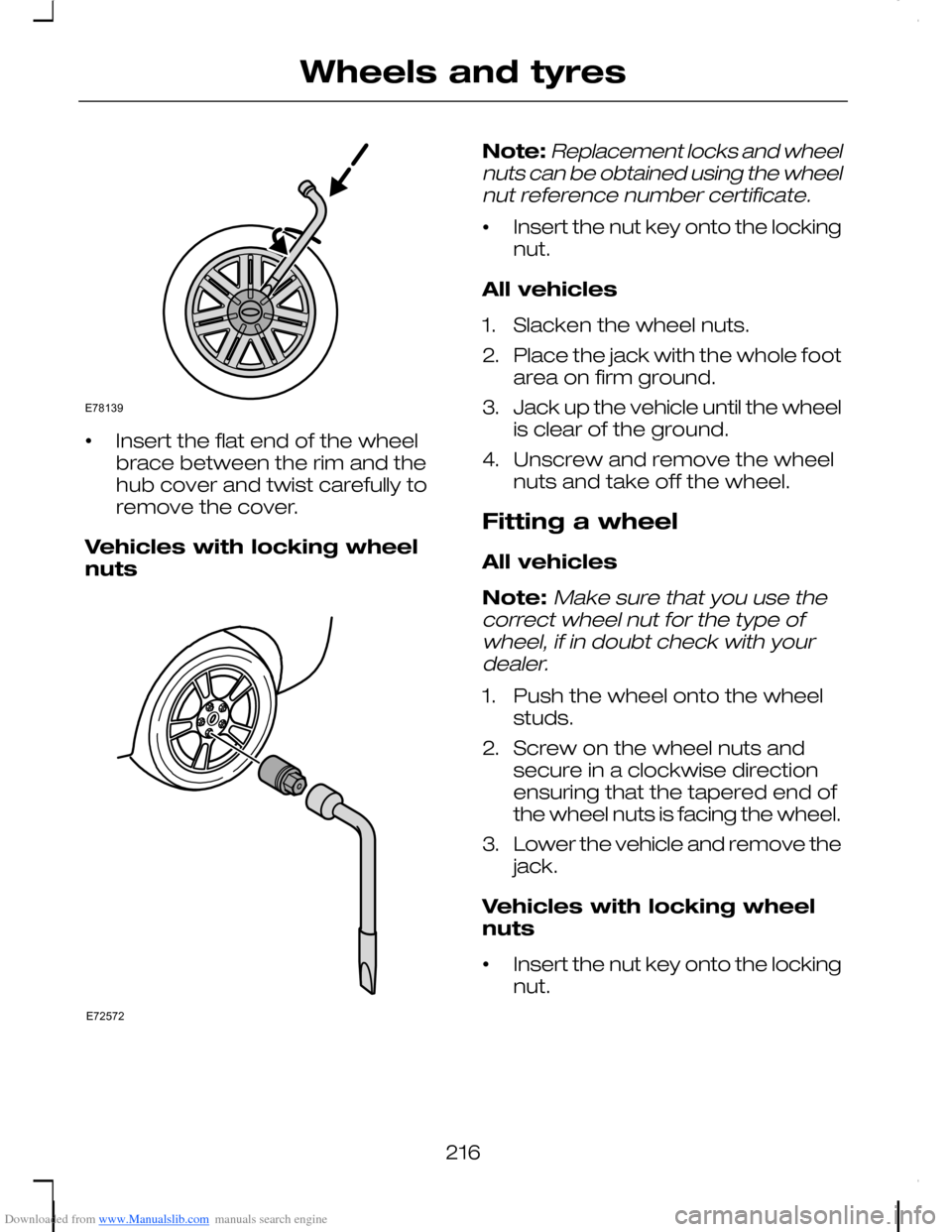
Downloaded from www.Manualslib.com manuals search engine •Insert the flat end of the wheelbrace between the rim and thehub cover and twist carefully toremove the cover.
Vehicles with locking wheelnuts
Note:Replacement locks and wheelnuts can be obtained using the wheelnut reference number certificate.
•Insert the nut key onto the lockingnut.
All vehicles
1.Slacken the wheel nuts.
2.Place the jack with the whole footarea on firm ground.
3.Jack up the vehicle until the wheelis clear of the ground.
4.Unscrew and remove the wheelnuts and take off the wheel.
Fitting a wheel
All vehicles
Note:Make sure that you use thecorrect wheel nut for the type ofwheel, if in doubt check with yourdealer.
1.Push the wheel onto the wheelstuds.
2.Screw on the wheel nuts andsecure in a clockwise directionensuring that the tapered end ofthe wheel nuts is facing the wheel.
3.Lower the vehicle and remove thejack.
Vehicles with locking wheelnuts
•Insert the nut key onto the lockingnut.
216
Wheels and tyresE78139 E72572
Page 223 of 278
Downloaded from www.Manualslib.com manuals search engine Bottle holderE
Pressure gaugeF
Power plug with cableG
Compressor switchH
LabelI
Bottle lidJ
Sealant bottleK
1.Open the lid of the tyre repair kit.
2.Peel off the label I showing themaximum permissible speed of80 km/h (50 mph) from the casingand attach it to the instrumentpanel in the driver’s field of view.Make sure the label does notobscure anything important.
3.Take the hose C and the powerplug with cable G out of the kit.
4.Unscrew the orange cap D andthe bottle lid J.
5.Screw the sealant bottle Kclockwise into the bottle holder Efully tight.
6.Remove the valve cap from thedamaged tyre.
7.Detach the protective cap A fromthe hose C and screw the hoseC firmly onto the valve of thedamaged tyre.
8.Make sure that the compressorswitch H is in position 0.
9.Insert the power plug G into thecigar lighter socket or auxiliarypower socket. See Cigarlighter (page 134). See Auxiliarypower sockets (page 134).
10.Start the engine.
11.Move the compressor switch Hto position 1.
12.Inflate the tyre for no longer thanseven minutes to an inflationpressure of minimum 1.8 bar(26 psi) and a maximum of3.5 bar (51 psi). Move thecompressor switch H to position0 and check the current tyrepressure with pressure gaugeF.
13.Remove the power plug G fromthe cigar lighter socket orauxiliary power socket.
14.Quickly unscrew the hose Cfrom the tyre valve and replacethe protective cap A. Fasten thevalve cap again.
15.Leave the sealant bottle K in thebottle holder E.
16.Make sure the kit, the bottle lidand the orange cap are storedsafely, but still easily accessiblein the vehicle. The kit will berequired again when you checkthe tyre pressure.
221
Wheels and tyres
Page 272 of 278
Downloaded from www.Manualslib.com manuals search engine Manual transmission.....................154Reverse gear − 5-speedtransmission....................................154Reverse gear − 6-speedtransmission....................................154
Message centreSee: Information displays...................96
MirrorsSee: Heated windows and mirrors...114See: Windows and mirrors.................84
N
Navigation systemcommands..................................252
O
Occupant protection......................27Principle of operation..........................27
Oil checkSee: Engine oil check.......................200
Opening and closing thebonnet..........................................189Closing the bonnet............................189Opening the bonnet..........................189
P
Parking aid......................................162Principle of operation........................162
Parking aidSee: Using the parking aid................162
Parking brake.................................159All vehicles...........................................159
Parts and accessories......................7Look for the Ford logo on thefollowing parts ....................................8Now you can be sure that your Fordparts are Ford parts...........................7
Pedals...............................................58
Personalised settings.....................99Auxiliary heater programming..........100Car Setup menu..................................99Chime deactivation............................102Clock setting.......................................100ESP.......................................................100Language setting...............................100Units of measure................................100
Power steering fluid check.........202Vehicles with 1.4L Duratec-16V(Sigma) or 1.6L Duratec-16V(Sigma) or 1.6L Duratec-16V Ti-VCT(Sigma) engine...............................202Vehicles with 1.8L Duratec-HE (MI4)or 2.0L Duratec-HE (MI4) or 2.5LDuratec-ST (VI5) or 1.6LDuratorq-TDCi (DV) Diesel or 1.8LDuratorq-TDCi (Kent) Diesel or 2.0LDuratorq-TDCi (Kent) Dieselengine.............................................203
Programming the remotecontrol............................................35Reprogramming the unlockingfunction..............................................36
Q
Quick start.........................................10
R
Rear fog lamps................................65Rear seats......................................124Comfort seat system........................124Folding the seatbacks forward........125Folding the seats forward.................127Installing the seats..............................131Removing the seats..........................130Returning the seatbacks to theupright position...............................126Returning the seats to the seatingposition............................................129
270
Index