stop start FORD C MAX 2011 2.G Owner's Manual
[x] Cancel search | Manufacturer: FORD, Model Year: 2011, Model line: C MAX, Model: FORD C MAX 2011 2.GPages: 296, PDF Size: 7.87 MB
Page 139 of 296
Downloaded from www.Manualslib.com manuals search engine CAUTIONS
Do not push-start or tow-start your
vehicle. Use booster cables. See
Jump-Starting the Vehicle (page
197). Do not switch the ignition off when
driving.
FUEL FILLER FLAP
WARNINGS
Take care when refuelling to avoid
spilling any residual fuel from the fuel
nozzle.
Do not use any kind of flames or heat
near the fuel system. The fuel system
is under pressure. There is a risk of
injury if the fuel system is leaking. CAUTION
If you use a high pressure spray to
wash your vehicle, only spray the fuel
filler flap briefly from a distance not
less than 200 millimetres (8 inches). Note:
The sliding door is inhibited from
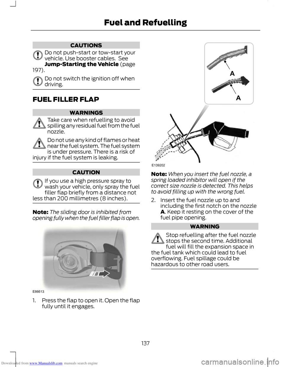
opening fully when the fuel filler flap is open. 1.
Press the flap to open it. Open the flap
fully until it engages. Note:
When you insert the fuel nozzle, a
spring loaded inhibitor will open if the
correct size nozzle is detected. This helps
to avoid filling up with the wrong fuel.
2. Insert the fuel nozzle up to and including the first notch on the nozzle
A. Keep it resting on the cover of the
fuel pipe opening. WARNING
Stop refuelling after the fuel nozzle
stops the second time. Additional
fuel will fill the expansion space in
the fuel tank which could lead to fuel
overflowing. Fuel spillage could be
hazardous to other road users. 137
Fuel and RefuellingE86613 E139202AA
Page 140 of 296
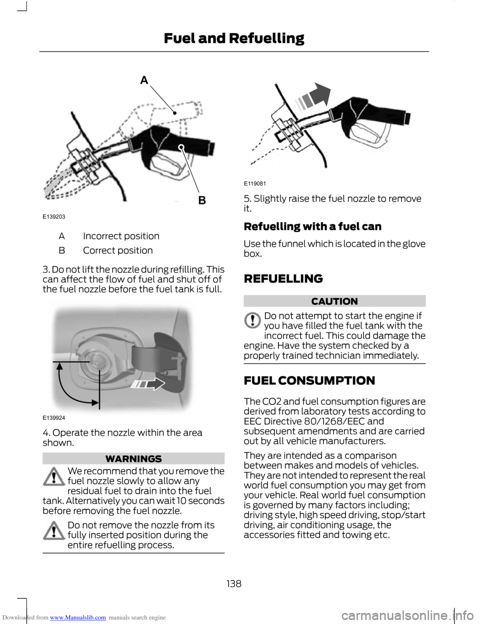
Downloaded from www.Manualslib.com manuals search engine Incorrect position
A
Correct position
B
3. Do not lift the nozzle during refilling. This
can affect the flow of fuel and shut off of
the fuel nozzle before the fuel tank is full. 4. Operate the nozzle within the area
shown.
WARNINGS
We recommend that you remove the
fuel nozzle slowly to allow any
residual fuel to drain into the fuel
tank. Alternatively you can wait 10 seconds
before removing the fuel nozzle. Do not remove the nozzle from its
fully inserted position during the
entire refuelling process. 5. Slightly raise the fuel nozzle to remove
it.
Refuelling with a fuel can
Use the funnel which is located in the glove
box.
REFUELLING
CAUTION
Do not attempt to start the engine if
you have filled the fuel tank with the
incorrect fuel. This could damage the
engine. Have the system checked by a
properly trained technician immediately. FUEL CONSUMPTION
The CO2 and fuel consumption figures are
derived from laboratory tests according to
EEC Directive 80/1268/EEC and
subsequent amendments and are carried
out by all vehicle manufacturers.
They are intended as a comparison
between makes and models of vehicles.
They are not intended to represent the real
world fuel consumption you may get from
your vehicle. Real world fuel consumption
is governed by many factors including;
driving style, high speed driving, stop/start
driving, air conditioning usage, the
accessories fitted and towing etc.
138
Fuel and RefuellingE139203AB E139924 E119081
Page 141 of 296
Downloaded from www.Manualslib.com manuals search engine Your Ford dealer can give you advice on
improving your fuel consumption.
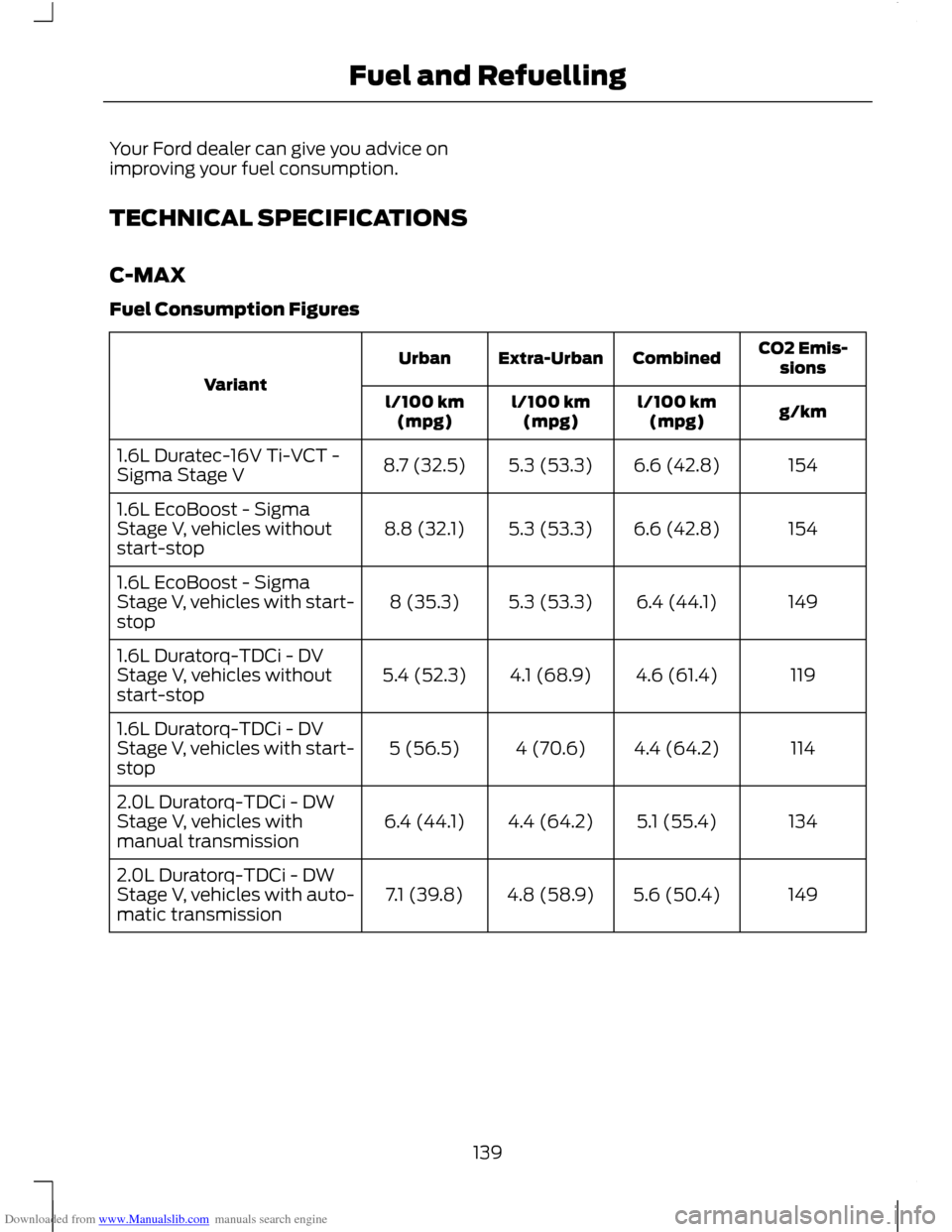
TECHNICAL SPECIFICATIONS
C-MAX
Fuel Consumption Figures
CO2 Emis-
sions
Combined
Extra-Urban
Urban
Variant g/km
l/100 km
(mpg)
l/100 km
(mpg)
l/100 km
(mpg)
154
6.6 (42.8)
5.3 (53.3)
8.7 (32.5)
1.6L Duratec-16V Ti-VCT -
Sigma Stage V
154
6.6 (42.8)
5.3 (53.3)
8.8 (32.1)
1.6L EcoBoost - Sigma
Stage V, vehicles without
start-stop
149
6.4 (44.1)
5.3 (53.3)
8 (35.3)
1.6L EcoBoost - Sigma
Stage V, vehicles with start-
stop
119
4.6 (61.4)
4.1 (68.9)
5.4 (52.3)
1.6L Duratorq-TDCi - DV
Stage V, vehicles without
start-stop
114
4.4 (64.2)
4 (70.6)
5 (56.5)
1.6L Duratorq-TDCi - DV
Stage V, vehicles with start-
stop
134
5.1 (55.4)
4.4 (64.2)
6.4 (44.1)
2.0L Duratorq-TDCi - DW
Stage V, vehicles with
manual transmission
149
5.6 (50.4)
4.8 (58.9)
7.1 (39.8)
2.0L Duratorq-TDCi - DW
Stage V, vehicles with auto-
matic transmission
139
Fuel and Refuelling
Page 142 of 296
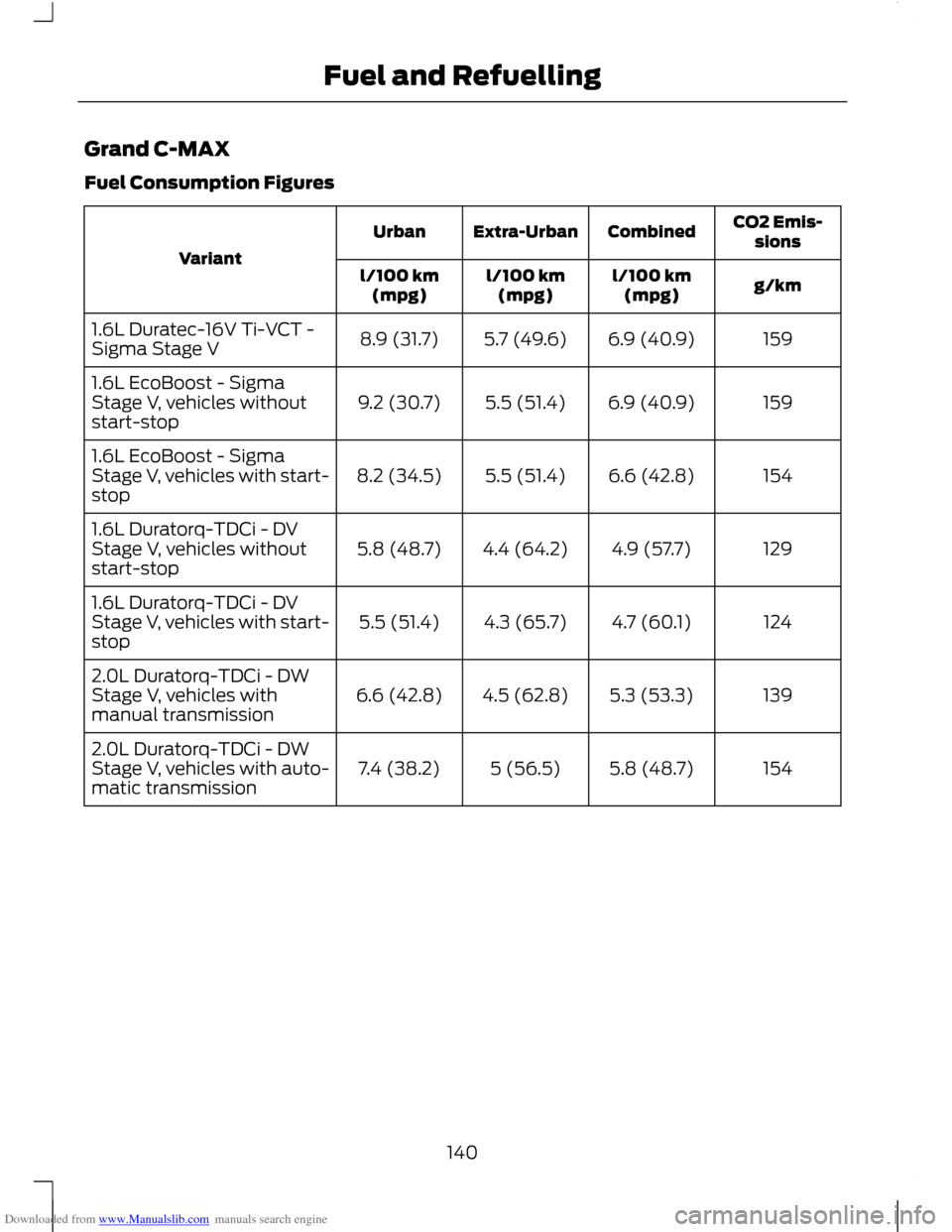
Downloaded from www.Manualslib.com manuals search engine Grand C-MAX
Fuel Consumption Figures
CO2 Emis-
sions
Combined
Extra-Urban
Urban
Variant g/km
l/100 km
(mpg)
l/100 km
(mpg)
l/100 km
(mpg)
159
6.9 (40.9)
5.7 (49.6)
8.9 (31.7)
1.6L Duratec-16V Ti-VCT -
Sigma Stage V
159
6.9 (40.9)
5.5 (51.4)
9.2 (30.7)
1.6L EcoBoost - Sigma
Stage V, vehicles without
start-stop
154
6.6 (42.8)
5.5 (51.4)
8.2 (34.5)
1.6L EcoBoost - Sigma
Stage V, vehicles with start-
stop
129
4.9 (57.7)
4.4 (64.2)
5.8 (48.7)
1.6L Duratorq-TDCi - DV
Stage V, vehicles without
start-stop
124
4.7 (60.1)
4.3 (65.7)
5.5 (51.4)
1.6L Duratorq-TDCi - DV
Stage V, vehicles with start-
stop
139
5.3 (53.3)
4.5 (62.8)
6.6 (42.8)
2.0L Duratorq-TDCi - DW
Stage V, vehicles with
manual transmission
154
5.8 (48.7)
5 (56.5)
7.4 (38.2)
2.0L Duratorq-TDCi - DW
Stage V, vehicles with auto-
matic transmission
140
Fuel and Refuelling
Page 147 of 296
Downloaded from www.Manualslib.com manuals search engine PRINCIPLE OF OPERATION
Electronic stability programme
(ESP)
WARNING
ESP does not relieve you of your
responsibility to drive with due care
and attention.
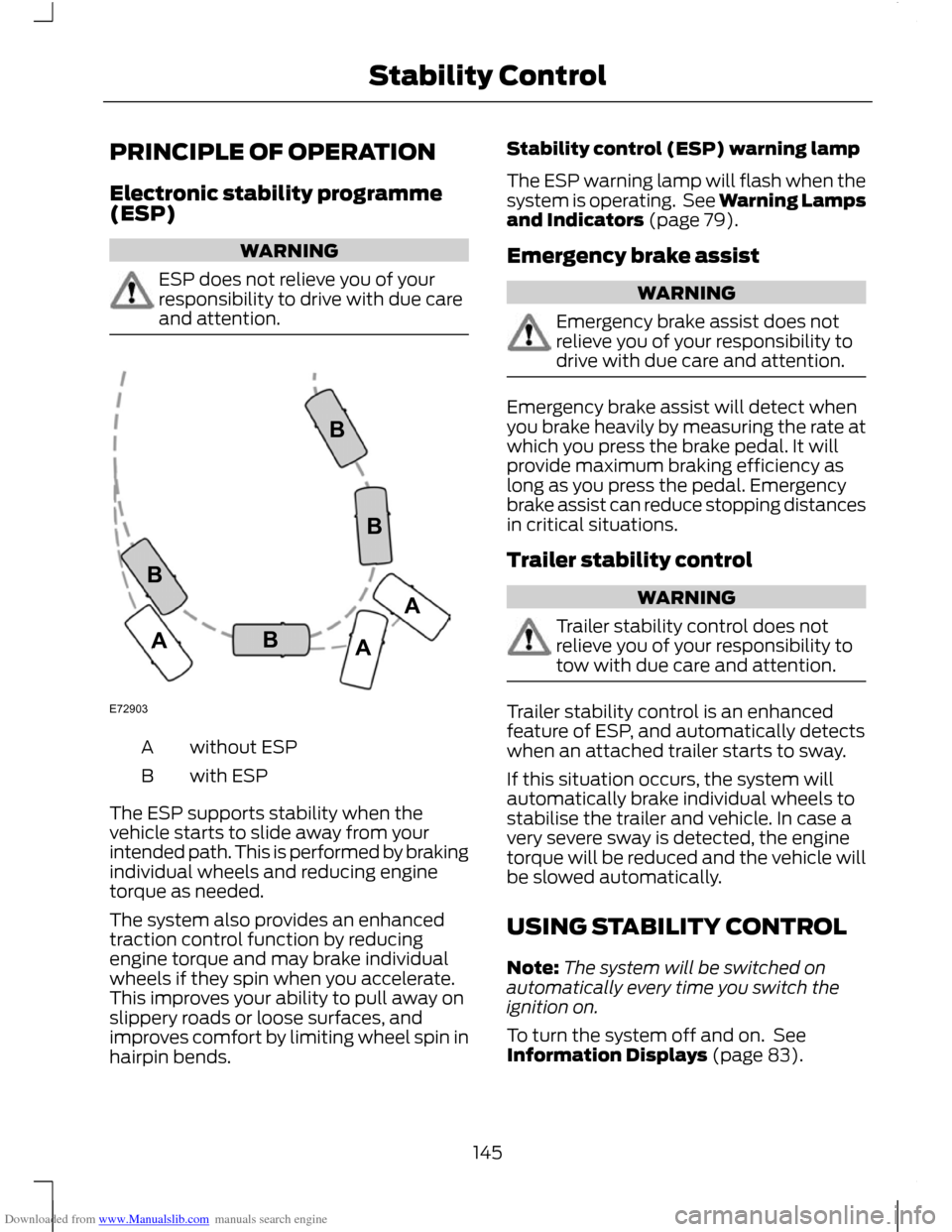
without ESP
A
with ESP
B
The ESP supports stability when the
vehicle starts to slide away from your
intended path. This is performed by braking
individual wheels and reducing engine
torque as needed.
The system also provides an enhanced
traction control function by reducing
engine torque and may brake individual
wheels if they spin when you accelerate.
This improves your ability to pull away on
slippery roads or loose surfaces, and
improves comfort by limiting wheel spin in
hairpin bends. Stability control (ESP) warning lamp
The ESP warning lamp will flash when the
system is operating. See Warning Lamps
and Indicators (page 79).
Emergency brake assist
WARNING
Emergency brake assist does not
relieve you of your responsibility to
drive with due care and attention.
Emergency brake assist will detect when
you brake heavily by measuring the rate at
which you press the brake pedal. It will
provide maximum braking efficiency as
long as you press the pedal. Emergency
brake assist can reduce stopping distances
in critical situations.
Trailer stability control
WARNING
Trailer stability control does not
relieve you of your responsibility to
tow with due care and attention.
Trailer stability control is an enhanced
feature of ESP, and automatically detects
when an attached trailer starts to sway.
If this situation occurs, the system will
automatically brake individual wheels to
stabilise the trailer and vehicle. In case a
very severe sway is detected, the engine
torque will be reduced and the vehicle will
be slowed automatically.
USING STABILITY CONTROL
Note:
The system will be switched on
automatically every time you switch the
ignition on.
To turn the system off and on. See
Information Displays (page 83).
145
Stability ControlE72903AAABBBB
Page 148 of 296
Downloaded from www.Manualslib.com manuals search engine PRINCIPLE OF OPERATION
The system makes it easier to pull away
when the vehicle is on a slope without the
need to use the parking brake.
When the system is active, the vehicle will
remain stationary on the slope for a short
time after you release the brake pedal.
During this time, you have time to move
your foot from the brake to the accelerator
pedal and pull away. The brakes are
released automatically once the engine
has developed sufficient drive to prevent
the vehicle from rolling down the slope.
This is an advantage when pulling away
on a slope, for example from a car park
ramp, traffic lights or when reversing uphill
into a parking space.
WARNING
The system does not replace the
parking brake. When you leave the
vehicle, always apply the parking
brake and select first or reverse gear. USING HILL START ASSIST
The system is activated automatically
when you stop your vehicle on a slope
greater than 3%. The system operates with
the vehicle facing downhill if reverse gear
is selected and with the vehicle facing
uphill if any forward gear is selected.
Vehicles with manual
transmission only
The system can be switched on and off
using the information display. See General
Information (page 83).
Activating the system
WARNINGS
You must remain in the vehicle once
you have activated the system. WARNINGS
At all times you are responsible for
controlling the vehicle, supervising
the system and intervening, if
required. If a malfunction is detected when the
system is active, the system will be
deactivated and a message will be
shown in the display. See Information
Messages (page 90). You can activate the system only if the
following conditions have been met:
•
The engine is running.
• The system is switched on.
• On vehicles with manual transmission,
the clutch pedal is pressed.
• No failure mode is present.
To activate the system:
1. Press the brake pedal to bring the vehicle to a complete standstill. Keep
the brake pedal depressed.
2. If the sensors detect that the vehicle is
on a slope the system will be activated
automatically.
3. When you remove your foot from the brake pedal, the vehicle will remain on
the slope without rolling away for a
short time. This hold time will
automatically be extended if you are
in the process of driving off.
4. Drive off in the normal manner. The brakes will be released automatically.
Deactivating the system
To deactivate the system, perform one of
the following:
146
Hill Start Assist
Page 200 of 296
Downloaded from www.Manualslib.com manuals search engine CAUTIONS
Do not connect to the negative (–)
terminal of the flat battery.
Make sure that the cables are clear of
any moving parts and fuel delivery
system parts.
To start the engine
1. Run the engine of vehicle B at
moderately high speed.
2. Start the engine of vehicle A.
3. Run both vehicles for a minimum of three minutes before disconnecting the
cables. CAUTION
Do not switch on the headlamps when
disconnecting the cables. The peak
voltage could blow the bulbs.
Disconnect the cables in the reverse order.
CHANGING THE VEHICLE
BATTERY
CAUTION
For vehicles with Start-stop the
battery requirement is different. It
must be replaced by one of exactly
the same specification as the original. Note:
Where applicable, the audio system
must be reprogrammed with the keycode.
The battery is located in the engine
compartment. See Maintenance (page
185). BATTERY CONNECTION
POINTS CAUTION
Do not connect to the negative (–)
terminal of the flat battery.
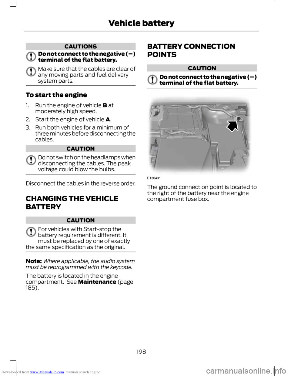
The ground connection point is located to
the right of the battery near the engine
compartment fuse box.
198
Vehicle batteryE130431
Page 208 of 296
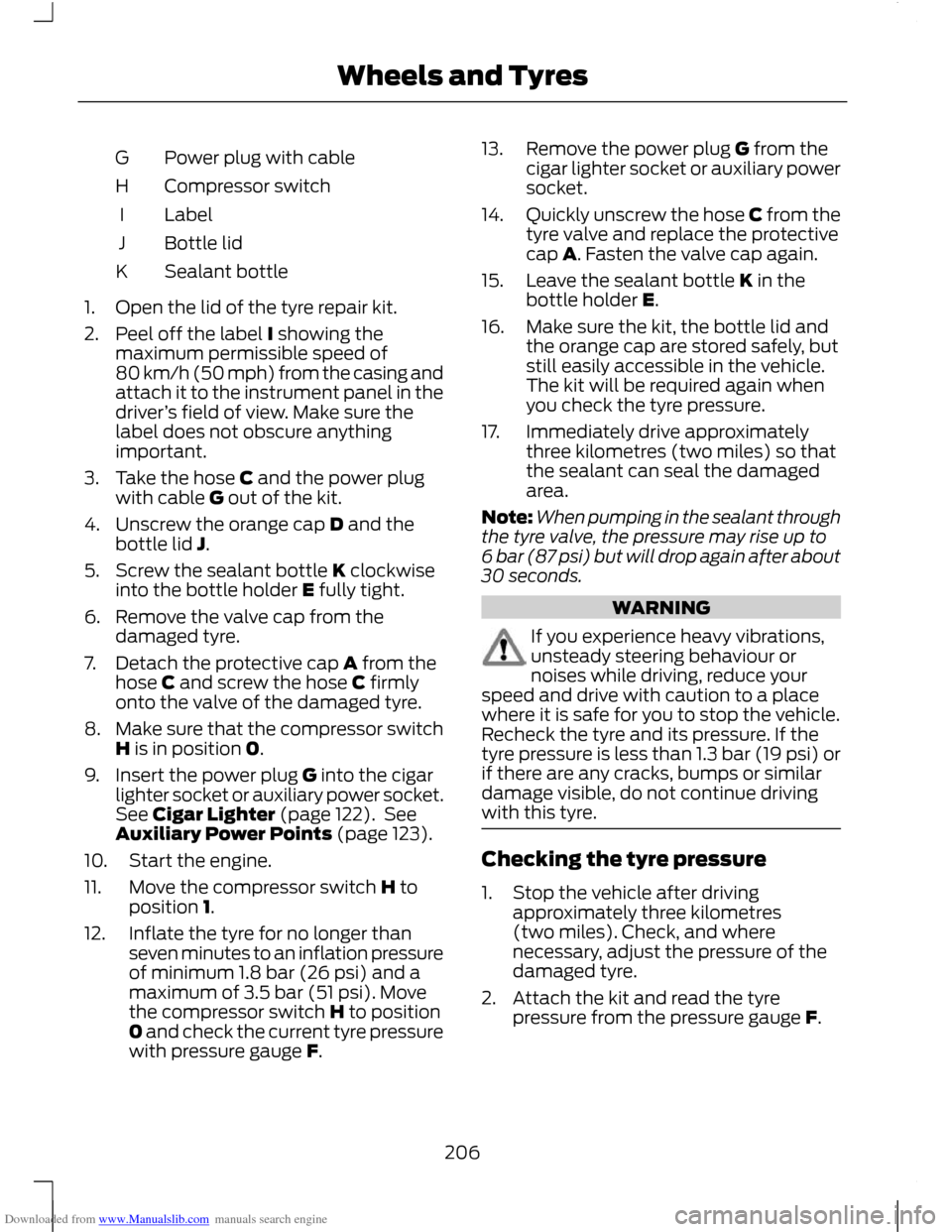
Downloaded from www.Manualslib.com manuals search engine Power plug with cable
G
Compressor switch
H
Label
I
Bottle lid
J
Sealant bottle
K
1. Open the lid of the tyre repair kit.
2. Peel off the label I showing the maximum permissible speed of
80 km/h (50 mph) from the casing and
attach it to the instrument panel in the
driver ’s field of view. Make sure the
label does not obscure anything
important.
3. Take the hose C and the power plug with cable G out of the kit.
4. Unscrew the orange cap D and the bottle lid J.
5. Screw the sealant bottle K clockwise into the bottle holder E fully tight.
6. Remove the valve cap from the damaged tyre.
7. Detach the protective cap A from the hose C and screw the hose C firmly
onto the valve of the damaged tyre.
8. Make sure that the compressor switch
H is in position 0.
9. Insert the power plug G into the cigar lighter socket or auxiliary power socket.
See Cigar Lighter (page 122). See
Auxiliary Power Points (page 123).
10. Start the engine.
11. Move the compressor switch H to position 1.
12. Inflate the tyre for no longer than seven minutes to an inflation pressure
of minimum 1.8 bar (26 psi) and a
maximum of 3.5 bar (51 psi). Move
the compressor switch H to position
0 and check the current tyre pressure
with pressure gauge F. 13. Remove the power plug G from the
cigar lighter socket or auxiliary power
socket.
14. Quickly unscrew the hose C from the
tyre valve and replace the protective
cap A. Fasten the valve cap again.
15. Leave the sealant bottle K in the bottle holder E.
16. Make sure the kit, the bottle lid and the orange cap are stored safely, but
still easily accessible in the vehicle.
The kit will be required again when
you check the tyre pressure.
17. Immediately drive approximately three kilometres (two miles) so that
the sealant can seal the damaged
area.
Note: When pumping in the sealant through
the tyre valve, the pressure may rise up to
6 bar (87 psi) but will drop again after about
30 seconds. WARNING
If you experience heavy vibrations,
unsteady steering behaviour or
noises while driving, reduce your
speed and drive with caution to a place
where it is safe for you to stop the vehicle.
Recheck the tyre and its pressure. If the
tyre pressure is less than 1.3 bar (19 psi) or
if there are any cracks, bumps or similar
damage visible, do not continue driving
with this tyre. Checking the tyre pressure
1. Stop the vehicle after driving
approximately three kilometres
(two miles). Check, and where
necessary, adjust the pressure of the
damaged tyre.
2. Attach the kit and read the tyre pressure from the pressure gauge F.
206
Wheels and Tyres
Page 235 of 296
Downloaded from www.Manualslib.com manuals search engine When an MP3 CD is playing, options
include REPEAT for the track, or to repeat
all the tracks in the folder. Repeat presses
of function button 1 will toggle these
options.
COMPACT DISC TRACK
SCANNING
The SCAN function allows you to preview
each track for approximately 5 seconds.
Type 1
Various scan modes are possible,
according to the type of CD currently
playing.
1. Press the MENU button and select CD
MODE.
2. Select SCAN, which then enables the function to be selected on or off.
Note: When an MP3 CD is playing, options
include SCAN for the CD, or just the tracks
in the folder.
3. Press the OK button to stop the scan mode.
Type 2 and 3
1. Press function button 3.
Note: When an MP3 CD is playing, options
include SCAN for the CD, or just the tracks
in the folder. Repeat presses of function
button 3 will toggle these options.
2. Press function button 3 again to stop the scan mode.
MP3 FILE PLAYBACK
Note: Some copy protected audio files may
not be read by the CD player.
The CD player also supports MP3 and
WMA format audio files. When a CD containing audio is inserted
into the CD player the disc's directory
structure is read in. It may take a while
before playback starts and is dependant
on the quality of the disc.
MP3 tracks may be recorded on the CD in
several ways. They can all be placed in the
root directory like a conventional audio CD,
or they can be placed in folders that may
represent, for example, an album, an artist,
or a genre.
Playing a multi session disc
The normal playing sequence on CD's with
multiple folders is to play the tracks in the
first folder, then the tracks in any folders
nested inside the first folder, then move
onto the second folder, and so on. For
example, if folder 1 has folders 1a and 1b
within it, and folder 2 contains folder 2a,
the playing sequence will be folder 1, 1a, 1b,
2, 2a.
When the playback of a file is finished the
playback of the other files in the same
directory continues. Directory change takes
place automatically when all files in the
current directory have been played back.
MP3 DISPLAY OPTIONS
When an MP3 disc is playing, certain
information encoded in each track can be
displayed. Such information will normally
include:
•
The file name
• The folder name
• ID3 information which might be the
album or artist’ s name.
The unit will normally show the file name
that is playing. To select one of the other
items of information, press the INFO
button repeatedly until the required item
is shown in the display.
233
Compact disc player
Page 264 of 296
Downloaded from www.Manualslib.com manuals search engine GENERAL INFORMATION
Press the relevant button on the unit bezel
to access the system functions. This will
take you into the selected mode.
One hour mode
To conserve battery power, the system can
be operated in one hour mode. If the
ignition is off, press the ON/OFF button to
switch the system on. The system will
automatically switch off after one hour.
System notes
WARNINGS
The front glass on the liquid crystal
display may break if hit with a hard
object. If the glass breaks, do not
touch the liquid crystalline material. In case
of contact with the skin, wash immediately
with soap and water. The unit is a highgrade laser product
which uses an invisible laser beam.
If this is handled incorrectly it can
emit dangerous rays. Do not attempt to
look through any openings in the unit. CAUTIONS
Irregular shaped CDs and CDs with a
scratch protection film or self
adhesive labels attached should not
be used. Warranty claims, where this type
of disc is found to be inside an audio unit
returned for repair, will not be accepted. Do not clean the unit with solvents or
aerosol cleaning agents. Use only a
damp cloth.
Do not insert foreign objects into any
of the unit disc drives or media card
slots.
Do not insert more than one disc into
the unit disc drive. CAUTIONS
Use only 12 cm (4.7 inches) discs or 8
cm (3.1 inches) discs with a suitable
adaptor.
Do not attempt to open the unit. If the
unit malfunctions consult your dealer.
Improper use of settings and
connections, other than those
explained in this handbook, can
damage the unit. Do not turn the ignition key or attempt
to start the engine while the software
is updating.
The system is recommended for use when
the ignition key is turned to the accessory
position or when the engine is running. If
the system is used extensively when the
engine is not running, care needs to be
taken to avoid draining the battery.
ROAD SAFETY
WARNINGS
The system provides you with
information designed to help you
reach your destination quickly and
safely. For reasons of safety, the driver
should only program the system
when the vehicle is stationary.
The system provides no assistance
with respect to stop signs, traffic
lights, areas under construction or
other important safety information. Do not use the system until you have
familiarised yourself with its
operation.
Only view the system display when
driving conditions permit.
262
Navigation introduction